Note : Les descriptions sont présentées dans la langue officielle dans laquelle elles ont été soumises.
CA 02763096 2011-12-20
ROCK CRUSHER ATTACHMENT
FIELD OF THE INVENTION
[0001] The present invention relates to the field of rock crushers, in
particular, rock crusher
attachments for earthmoving vehicles or the like.
BACKGROUND OF THE INVENTION
[0002] Rotary crushers are used in a variety of mining applications as well as
in
construction/demolition settings. A typical rotary crusher has a housing made
of steel plate, a
first fixed jaw and a second movable jaw positioned facing each other inside
the housing. When
the rotary crusher is actuated, the second movable jaw is urged to move
between an open jaw
setting (where the gap between the first end of the second movable jaw and the
fixed jaw is at its
greatest) and a closed jaw setting (where the gap between first end of the
second movable jaw
and the fixed jaw is at its smallest). When the second movable jaw in the
closed jaw setting, a
crushing force is delivered to the rock held between the jaws.
[0003] Different mechanisms have been used to actuate the movable jaw. One
known
mechanism employs a hydraulic motor and a drive belt and pulley arrangement
operatively
connected to a drive shaft. A pair of eccentrics is arranged on the drive
shaft. Each eccentric is
provided with a bearing. A hollow sleeve fixed to the movable jaw fits on the
bearings and can
freely rotate about the bearings. When the hydraulic motor is actuated, rotary
motion is
transferred through the drive belt and pulley arrangement to the drive shaft.
As the shaft rotates,
the eccentrics bear against the sleeve and a rotational/translational movement
is imparted to the
movable jaw thereby urging the movable jaw closer to fixed jaw to deliver the
crushing force.
Also provided is an adjustment mechanism for adjusting the cross-section of
the discharge outlet
of the crusher. The adjustment mechanism takes the form of a strut and one or
more spacers
interposed between the frame of the movable jaw and a portion of the crusher
housing. A spring
member holds the adjustment mechanism in place during the movement of the jaw.
[0004] Other known actuating mechanisms employ an arrangement of drive motor,
eccentric
shaft and toggle mechanism. The drive motor is connected to one end of the
eccentric shaft,
DM_TOR/28 1 003-0000 1 /36742973
CA 02763096 2011-12-20
- 2 -
while a flywheel is rigidly fixed to the opposite end of the eccentric shaft.
A pitman is held
against the eccentric shaft and is arranged to bear against the toggle pin of
the toggle mechanism.
The toggle mechanism is defined by the toggle pin and a pair of opposed first
and second toggle
plates disposed in bearing engagement with toggle pin. Each toggle plate is
mounted to extend
between the toggle pin and a toggle seat. The toggle seat of the first toggle
plate is carried on the
crusher housing, while the toggle seat of the second plate is supported on the
movable jaw. All
the parts of the toggle mechanism are held firmly together by springs. When
the crusher is
actuated, the drive motor causes the eccentric shaft to rotate. The rotary
motion urges the
displacement of the pitman thereby causing the toggle plates to reciprocate
and the movable jaw
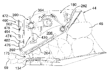
to pivot towards the fix jaw. A pull back spring mechanism is also provided to
bias the movable
jaw in the open setting position.
[0005] Crushers using the known jaw actuating mechanisms described above have
tended to
have only partial success in the field. While they tend to be generally
effective at crushing softer
rock in the range of 20,000 to 25,000 psi hardness, they have tended not to
perform as well in
applications requiring harder rock to be crushed. In some cases where attempts
were made to
crush harder rock using such crushers, the crusher mechanism lacked the
requisite crushing
power to crush the rock, and stalled. Worse still, in some extreme cases, the
frames supporting
the moving and fixed jaws flexed under the stress of crushing the harder rock,
and failed.
[0006] Another drawback associated with these types of crushers is their
inability to crush
relatively large volumes of rock in a short period of time (i.e. that is more
than 50 tons per hour),
without substantially increasing the size of the crushing mechanism (and
consequently, the cost
of the crusher).
[0007] For reasons of versatility, it is desirable to have a crusher whose
crushing mechanism is
capable of being adjusted to produce crushed rock of a smaller or larger size,
as required. While
some of the crushers of the type described above have this capability,
adjusting the crushing
mechanism to increase or reduce the crushing size can be a complicated, labour-
intensive and
time-consuming task, in some cases, requiring two or more workers several
hours of work to
complete. Moreover, due to its complexity, such work tends not to be performed
in the field and
usually needs to be carried out at a maintenance/repair facility.
DM:1 OR/281003-00001/3674297 3
CA 02763096 2011-12-20
-3-
100081 Based on the foregoing, there is a real need for a ruggedly built rock
crusher that is
powerful enough to crush relatively large volumes of hard rock in a short
period of time.
Preferably, the crusher mechanism of such a rock crusher would be configured
to allow for the
size of the crushed rock produced to be quickly and easily adjusted to suit
particular field
applications.
SUMMARY OF THE INVENTION
[0009] According to a broad aspect of an embodiment of the present invention,
there is
provided a rock crusher. The rock crusher includes a front bucket portion
configured for
scooping rocks to be crushed and a rear crusher portion connected to and in
communication with
the rear of the bucket portion. The crusher portion includes a housing and a
crushing assembly
accommodated within the housing. The housing includes a pair of spaced apart
side panels. The
crushing assembly has a lower jaw fixed between the side panels of the housing
and an upper
movable jaw mounted opposite and spaced apart from the lower jaw. The upper
movable jaw
assembly includes a support, an upper jaw plate attached to the underside of
the support and a
jaw-actuating drive assembly operable to urge the upper movable jaw assembly
to move between
an open jaw setting and a closed jaw setting. The support is pivotally
connected between the side
panels adjacent the front of the housing. The jaw-actuating drive assembly
includes at least one
motor carried by the support. The at least one motor is urged to move along
with the upper
movable jaw assembly relative to the lower jaw, when the crusher assembly is
actuated.
[0010] In an additional feature, the jaw-actuating drive assembly further
includes an eccentric
operatively coupled to the at least one motor for rotation, a double toggle
plate arrangement
mounted between the support and a top portion of the housing, and a stroke arm
disposed
between and connected to each of the eccentric and the double toggle plate
arrangement for
transferring motion from the eccentric to the double toggle plate arrangement.
[0011] In one feature, during actuation of the crusher assembly, the double
toggle plate
arrangement is on center when the stroke arm has reached the end of its
stroke. In an alternate
feature, during actuation of the crusher assembly, the double toggle plate
arrangement is over
center when the stroke arm has reached the end of its stroke.
DM_TOR/2 81003-00001/3674297.3
CA 02763096 2011-12-20
- 4 -
[0012] In a further feature, the double toggle plate arrangement has an upper
toggle plate, a
lower toggle plate, and a cylindrical shaft disposed between and in bearing
engagement with the
upper and lower toggle plates. The shaft is attached to the stroke arm.
Additionally, the upper
toggle plate has an upper edge and a lower edge. The upper edge of the upper
toggle plate has a
first roller member fixed thereto. The lower edge of the upper toggle plate
has a first arcuate
plate fixed thereto. The radius of curvature of the first arcuate contact
plate is configured to
correspond to the radius of curvature of the shaft. The lower toggle plate has
an upper edge and
a lower edge. The upper edge of the lower toggle plate has a second arcuate
plate fixed thereto.
The radius of curvature of the second arcuate contact plate is configured to
correspond to the
radius of curvature of the shaft. The lower edge of the lower toggle plate has
a second a roller
member fixed thereto.
[0013] In yet another feature, the crusher assembly is further provided with a
first seat member
configured to receive the first roller member and a second seat member
configured to receive the
second roller member. The first seat member is carried between the side panels
and defines at
least partially the top portion of the housing. The second seat member is
carried on the support.
[0014] In one feature, the first seat member has a slanted orientation and is
inclined forwardly
relative to a vertical axis.
[0015] In still another feature, the crusher assembly further includes an
upper bearing block
disposed within the first seat member. The upper bearing block is configured
for bearing
engagement with the first roller member. Optionally, the crusher assembly may
further include
at least one shim for insertion between the first seat member and the upper
bearing block for
spacing the upper bearing block from the first seat member.
[0016] In a further feature, the support has a base and a plane P that
intersects the base. The
second seat member is angled relative to the plane P of the base. In another
feature, the crusher
assembly further includes a lower bearing block disposed within the second
seat member. The
lower bearing block is configured for bearing engagement with the second
roller member.
Optionally, the crusher assembly may further include a dampening pad for
insertion between the
second seat member and the lower bearing block.
DM_I OR/281003-00001/3674297 3
CA 02763096 2011-12-20
- 5 -
[0017] In yet another feature, the double toggle plate arrangement is moveable
between a
flexed position and a fully extended position. When the double toggle plate
arrangement is in the
flexed position, the upper toggle plate has a skewed orientation relative to
the lower toggle plate
and the movable jaw assembly is in the open jaw setting. When the double
toggle plate
arrangement is in the fully-extended position, the upper toggle plate is in
planar alignment with
lower toggle plate and the movable jaw assembly is in the closed jaw setting.
[0018] In still another feature, the jaw-actuating drive assembly further
includes a biasing
assembly operable to maintain the double toggle plate arrangement in the
flexed position. The
biasing assembly is hydraulics-based and includes a hydraulic cylinder
connected between the
top portion of the housing and the carriage. In a further feature, the
hydraulic cylinder includes a
body, a piston rod mounted to extend within the body and a piston accommodated
within the
body and connected to the piston rod. The piston rod is moveable between a
retracted position
and an extended position. The body is pivotally attached to one of the support
and the top portion
of the housing and the piston rod is pivotally attached to the other of the
support and the top
portion of the housing. In one feature, the piston rod is in the extended
position when the double
toggle plate arrangement is in its fully-extended position. In another
feature, the biasing
assembly further includes an accumulator in fluid communication with the
hydraulic cylinder, a
reservoir for storing hydraulic fluid and a pump operable to charge the
accumulator with
hydraulic fluid from the reservoir.
[0019] In a further feature, the double toggle plate arrangement further
includes means for
discouraging dislocation of the shaft from between the upper and lower toggle
plates. The means
for discouraging dislocation of the shaft includes at least one guard member
located in front of
the shaft and at least one guard member located rearward of the shaft.
[0020] In one feature, the at least one motor includes first and second motors
operatively
coupled to either ends of the eccentric.
[0021] In another feature, the crusher assembly has a discharge outlet defined
between the
upper jaw plate and the lower jaw at the rear of the housing and further
includes means for
adjusting the size of the discharge outlet.
DM 1 OR/281003-00001/3674297 3
CA 02763096 2011-12-20
- 6 -
[0022] According to another broad aspect of an embodiment of the present
invention, there is
provided a rock crusher attachment for an earthmoving vehicle. The rock
crusher attachment
includes a front bucket portion configured for scooping rocks to be crushed
and a rear crusher
portion connected to and in communication with the rear of the bucket portion.
The crusher
portion includes a housing and a crushing assembly accommodated within the
housing. The
housing has a pair of spaced apart side panels. The crushing assembly includes
a lower jaw fixed
between the side panels of the housing and an upper movable jaw mounted
opposite and spaced
apart from the lower jaw. The upper movable jaw assembly is pivotally
connected between the
side panels adjacent the front of the housing. The upper movable jaw assembly
includes a
support, an upper jaw plate attached to the underside of the support and a jaw-
actuating drive
assembly carried on the support. The jaw-actuating drive assembly is operable
to urge the upper
movable jaw assembly to move between an open jaw setting and a closed jaw
setting. The jaw-
actuating drive assembly being urged to move along with upper movable jaw
assembly relative
to the lower jaw, when the crusher assembly is actuated.
[0023] According to yet another broad aspect of an embodiment of the present
invention, there
is provided a rock crusher attachment for an earthmoving vehicle. The rock
crusher attachment
includes a front bucket portion configured for scooping rocks to be crushed
and a first rear
crusher portion connected to and in communication with the rear of the bucket
portion. The first
crusher portion includes a first housing and a first crushing assembly
accommodated within the
first housing. The first housing includes a pair of spaced apart side panels.
The crushing
assembly includes a first lower jaw fixed between the side panels of the first
housing and a first
upper movable jaw mounted opposite and spaced apart from the first lower jaw.
The first upper
movable jaw assembly includes a first support and a first upper jaw plate
attached to the
underside of the first support. The first support is pivotally connected
between the side panels of
the first housing adjacent the front thereof.
[0024] Also provided is a second rear crusher portion connected to and in
communication with
the rear of the bucket portion. The second crusher portion is spaced away from
the first crusher
portion. The second crusher portion includes a second housing and a second
crushing assembly
accommodated within the second housing. The second housing includes a pair of
spaced apart
side panels. The second crushing assembly includes a second lower jaw fixed
between the side
DMJOR/281003-00001/3674297 3
CA 02763096 2011-12-20
- 7 -
panels of the second housing and a second upper movable jaw mounted opposite
and spaced
apart from the second lower jaw. The second movable upper jaw assembly
includes a second
support and a second upper jaw plate attached to the underside of the second
support. The second
support is pivotally connected between the side panels of the second housing
adjacent the front
thereof.
[0025] The rock crusher attachment also includes a jaw-actuating drive
assembly extending
between the first and second crusher assemblies. The jaw-actuating assembly is
operable to urge
the first and second upper movable jaw assemblies to move between their
respective open jaw
settings and closed jaw settings. The jaw-actuating drive assembly includes a
first drive
subassembly associated with the first crusher assembly, a second drive
subassembly associated
with the second crusher assembly and a mechanism for transmitting rotary
motion between the
first drive subassembly and the second drive subassembly. The first drive
subassembly includes a
first motor carried by the first support. The first motor is urged to move
along with the first upper
movable jaw assembly relative to the first lower jaw, when the first crusher
assembly is actuated.
The second drive subassembly includes a second motor carried by the second
support. The
second motor is urged to move along with the second upper movable jaw assembly
relative to the
second lower jaw, when the second crusher assembly is actuated.
[0026] In a further feature, the first drive subassembly further includes a
first eccentric
operatively coupled to the first motor for rotation, a first double toggle
plate arrangement
mounted between the first support and a top portion of the first housing, and
a first stroke arm
disposed between and connected to each of the first eccentric and the first
double toggle plate
arrangement for transferring motion from the first eccentric to the first
double toggle plate
arrangement. The second drive subassembly further includes a second eccentric
operatively
coupled to the second motor for rotation, a second double toggle plate
arrangement mounted
between the second support and a top portion of the second housing, and a
second stroke arm
disposed between and connected to each of the second eccentric and the second
double toggle
plate arrangement for transferring motion from the second eccentric to the
second double toggle
plate arrangement. The mechanism for transmitting rotary motion between the
first drive
subassembly and the second drive subassembly is a universal joint assembly.
The universal joint
D M_1 OR/281003-00001/3674297 3
CA 02763096 2011-12-20
- 8 -
assembly has a first portion operatively coupled to the first eccentric and a
second portion
operatively coupled to the second eccentric.
[0027] In another feature, the first eccentric is rotationally out-of-phase
relative to the second
eccentric, preferably, by an angle of 180 degrees.
[0028] In still another feature, the front bucket portion includes a centrally
disposed V-shaped
blade portion for directing rocks to be crushed to the first and second rear
crusher portions.
[0029] According to still another broad aspect of an embodiment of the present
invention,
there is provided a rock crusher attachment for an earthmoving vehicle. The
rock crusher
attachment has a front bucket portion configured for scooping rocks to be
crushed and a first rear
crusher portion connected to and in communication with the rear of the bucket
portion. The first
crusher portion includes a first housing and a first crushing assembly
accommodated within the
first housing. The first housing includes a pair of spaced apart side panels.
The first crushing
assembly includes a first lower jaw fixed between the side panels of the first
housing and a first
upper movable jaw mounted opposite and spaced apart from the first lower jaw.
The first upper
movable jaw assembly includes a first support, a first upper jaw plate
attached to the underside
of the first support and a first jaw-actuating drive assembly operable to urge
the upper movable
jaw assembly to move between an open jaw setting and a closed jaw setting. The
first support is
pivotally connected between the side panels of the first housing adjacent the
front thereof. The
first jaw-actuating drive assembly includes at least one motor carried by the
first support. The at
least one motor of the first jaw-actuating assembly is urged to move along
with the first upper
movable jaw assembly relative to the first lower jaw, when the first crusher
assembly is actuated.
[0030] Also provided is, a second rear crusher portion connected to and in
communication
with the rear of the bucket portion. The second crusher portion is spaced away
from the first
crusher portion. The second crusher portion includes a second housing and a
second crushing
assembly accommodated within the second housing. The second housing includes a
pair of
spaced apart side panels. The second crushing assembly including a second
lower jaw fixed
between the side panels of the second housing and a second upper movable jaw
mounted
opposite and spaced apart from the second lower jaw. The second upper movable
jaw assembly
includes a second support, a second upper jaw plate attached to the underside
of the second
DM_TO R/2 81003-00001/3674297 3
CA 02763096 2011-12-20
- 9 -
support and a second jaw-actuating drive assembly operable to urge the upper
movable jaw
assembly to move between an open jaw setting and a closed jaw setting. The
second support is
pivotally connected between the side panels of the second housing adjacent the
front thereof. The
second jaw-actuating drive assembly includes at least one motor carried by the
second support.
The at least one motor of the second jaw-actuating assembly is urged to move
along with the
second upper movable jaw assembly relative to the second lower jaw, when the
second crusher
assembly is actuated.
BRIEF DESCRIPTION OF THE DRAWINGS
[0031] The embodiments of the present invention shall be more clearly
understood with
reference to the following detailed description of the embodiments of the
invention taken in
conjunction with the accompanying drawings, in which:
[0032] FIG. 1 is a front left perspective view of a rock crusher attachment in
accordance with
an embodiment of the invention showing a front bucket portion joined to a rear
crushing portion;
[0033] FIG. 2 is a right side elevation view of the rock crusher attachment
illustrated in FIG. 1;
[0034] FIG. 3a is a left side elevation view of the rock crusher attachment
illustrated in FIG. 1;
[0035] FIG. 3b is a front right, perspective, cross-sectional view of rock
crusher attachment
illustrated in FIG. 3 taken along line "3a-3a" showing in isolation the axle
assembly used to
pivotally connect the upper jaw assembly to the housing of the rear crushing
portion;
[0036] FIG. 4 is a front end view of the rock crusher attachment illustrated
in FIG. 3 taken in
the direction of arrow "3" looking into the bucket portion of the rock crusher
attachment and
showing the opposed first and second jaws disposed therein;
[0037] FIG. 5 is a rear end view of the rock crusher attachment illustrated in
FIG. 1 with the
rear panel of the crusher portion housing removed to reveal internal details
thereof;
[0038] FIG. 6 is a front right perspective view of the rock crusher attachment
illustrated in
FIG. 1, with the front bucket portion removed and a portion of a protective
panel on the side
DMJOR/281003-00001/3674297 3
CA 02763096 2011-12-20
- 10 -
panel member of the housing removed for clarity, and the housing of the rear
crusher portion
shown partially exploded;
[0039] FIG. 7 is a front left perspective view of the rock crusher attachment
shown in FIG. 1,
with the front bucket portion and the housing of the rear crusher portion
omitted to reveal details
of the jaw-type crusher assembly and the drive assembly used to actuate same;
[0040] FIG. 8 is an exploded perspective view of the drive assembly shown in
FIG. 7;
[0041] FIG. 9 is a rear, isolated perspective view of the double toggle plate
arrangement
shown in FIG. 8;
[0042] FIG. 10 is a cross-sectional view of the rock crusher attachment
illustrated in FIG. 5
taken along line "10-10" showing the double toggle plate arrangement of the
drive assembly in
flexion;
[0043] FIG. 11 is a cross-sectional view of the rock crusher attachment
similar to that
illustrated in FIG. 10 showing the double toggle plate arrangement of the
drive assembly fully
straightened;
[0044] FIG. 12a is a view similar to that illustrated in FIG. 10, but
magnified to show the first
seat member of the double toggle plate arrangement;
[0045] FIG. 12b is a view similar to that illustrated in FIG. 10, but
magnified to show the
second seat member of the double toggle plate arrangement;
[0046] FIG. 13a is a partial view of the rock crusher attachment illustrated
in FIG. 10 showing
rocks loaded into the bucket portion of the rock crusher attachment;
[0047] FIG. 13b is a partial view of the rock crusher attachment illustrated
in FIG. 12a
showing the rocks being crushed between the first and second jaws of the rock
crusher
attachment;
[0048] FIG. 14 is a front right perspective view of twin rock crusher
attachment in accordance
with another embodiment of the present invention;
DM_TOR/281003-00001/3674297 3
CA 02763096 2011-12-20
- 11 -
[0049] FIG. 15 is a front end view of the rock crusher attachment illustrated
in FIG. 14 taken
in the direction of arrow "15" looking into the bucket portion of the twin
rock crusher
attachment;
[0050] FIG. 16 is a rear end elevation view of the twin rock crusher
attachment shown in FIG.
14;
[0051] FIG. 17 is a cross-sectional view of the twin rock crusher attachment
shown in FIG. 14
taken along line "17-17";
[0052] FIG. 18 is an isolated, perspective view of the twin rock crusher
attachment illustrated
in FIG. 14, with the bucket portion and the housings of each of the rear
crushing portions
removed to reveal the crusher assemblies, and the movable upper jaw assemblies
of the crusher
assemblies shown exploded from the rotary motion transmission device;
[0053] FIG. 19 is an isolated, front elevation view of the rotary motion
transmission device
shown in FIG. 18;
[0054] FIG. 20 is a rear perspective view of a twin rock crusher attachment
according to
another embodiment of the present invention; and
[0055] FIG. 21 is a rear end elevation view of the twin rock crusher
attachment shown in FIG.
20.
DETAILED DESCRIPTION OF EMBODIMENTS OF THE INVENTION
[0056] The description, which follows, and the embodiments described therein
are provided by
way of illustration of an example, or examples of particular embodiments of
principles and
aspects of the present invention. These examples are provided for the purposes
of explanation
and not of limitation, of those principles of the invention. In the
description that follows, like
parts are marked throughout the specification and the drawings with the same
respective
reference numerals.
[0057] Referring to FIGS. 1 to 6, there is shown a rock crusher attachment
designated
generally with reference numeral 20. The rock crusher attachment 20 is
designed to be
DM_1 OR/281003-00001/3674297 3
CA 02763096 2011-12-20
- 12 -
suspended from or carried on the boom (not shown) of an earthmoving vehicle,
such as an
excavator, a backhoe, a loader, or the like. The rock crusher attachment 20
has a front bucket
portion 22 and a rear crusher portion 24 joined thereto. The front bucket
portion 22 is provided
with a frame 26 welded to a bucket body 28. The frame 26 includes a top frame
member 30, an
opposed bottom blade-like lip member 32 and a pair of spaced apart, vertically
extending,
elongate side frame members 34 and 36 which join the top frame member 30 to
the bottom lip
member 32. In this embodiment, the top frame member 30 is in the nature of a C-
shaped
structural member 38 with its back 40 oriented frontward and its arms
extending 42 rearward
(see FIG. 9). A relatively large, substantially square, intake opening 44 is
defined in the frame
26 for receiving rocks to be crushed 46 (shown in FIG. 11a). The intake
opening 44 provides
access to the bucket body 28.
[0058] The bucket body 28 is defined by a top panel 50, a bottom panel 52, and
inwardly and
rearwardly extending side panel portions 54 and 56. The uppermost margin of
the top panel 50
is welded to the lower most margin of the top frame member 30. Portions of the
side edges of
the top panel 50 are also welded to the side frame members 34 and 36. The side
panel portions
54 and 56 are attached along their front edges to the side frame members 34
and 36. Lastly, the
bottom panel 52 is welded to the bottom lip member 32 along its front edge 58.
Arranged in this
manner, the panels 50 and 52 and the panel portions 54 and 56 form a chute 60
within the bucket
body 28. As best shown in FIG. 4, the chute 60 tapers in the rearward
direction, and ultimately
opens onto the rear crusher portion 24. To encourage travel of the rocks 46
toward the rear
crusher portion 24, both the top and bottom panels 50 and 52 are downwardly
sloping.
[0059] Three reinforcement ribs 62 are welded to the outer face of the bottom
panel 52. The
ribs 62 extend from the front edge 58 of the bottom panel 52 and project
beyond the rear edge 64
thereof for attachment to the rear crusher portion 24.
[0060] The rear crusher portion 24 has a housing 70 which accommodates a jaw-
type crusher
assembly 72. Referring to FIG. 6, the housing 70 has a front end 76 and rear
end 78, and further
includes a front protective face plate 80, an opposed rear protective face
plate 82, two spaced
apart, first and second side panel members 84 and 86, a top panel assembly 88
and a bottom
panel assembly 90. The front and rear face plates 80 and 82, and each of the
assemblies 88 and
DM_TOR/2 8 1 003-00001 /3674297 3
CA 02763096 2011-12-20
- 13 -
90 extend between and the first side panel member 84 and the second side panel
member 86 to
connect one to the other.
[0061] The front protective face plate 80 is mounted at the front end 76 of
the housing 70
adjacent the top panel assembly 88. It is relatively short and runs only about
one third of the way
down the first and second side panels 84 and 86. The front face plate 80
includes first, second
and third plate portions 92, 94 and 96. The second plate portion 94 extends
between the first and
third plate portions 92 and 96 and is bent rearward relative to the first
plate portion 92. The third
plate portion 96 is also bent rearward relative to the second plate portion 94
and extends
substantially horizontally away therefrom. During assembly of the front bucket
portion 22 and
the rear crusher portion 24, the distal ends of the arms 42 of the C-shaped
member 38 are welded
to the front face of face plate 80 adjacent the locations where the first
plate portion 92 meets the
second plate portion 94 and the second plate portion 94 meets the third plate
portion 96 (see FIG.
10).
[0062] The rear face plate 82 is disposed at the rear end 78 of the housing 70
and extends from
the top panel assembly 88 to a location roughly two thirds of the way down the
first and second
side panels 84 and 86. The rear face plate 82 includes first, second and third
plate portions 100,
102 and 104. The second plate portion 102 extends between the first and third
plate portions 100
and 104 and curves slightly rearward. The third plate portion 104 is also bent
rearward relative
to the second plate portion 102 and extends downwardly therefrom on an angle.
The rear face
plate 82 is hingedly mounted to the side panel member 84 along the lateral
edge of the first plate
portion 100.
[0063] Defined between the front and rear face plates 80 and 82, and the first
and second side
panel members 84 and 86, is a compartment 110 (best shown in FIGS. 10 and 11)
which
accommodates a portion of the crusher assembly 72.
[0064] The top panel assembly 88 includes first and second steel plates 112
and 114. The
bottom face of the first plate 112 is welded to the top edges 142 of the first
and second side panel
members 84 and 86. The first plate 112 has a relatively large aperture 116
formed therein to
allow access to the compartment 110. The second plate 114 is secured on top of
the first plate
112 by fasteners. The front portion 120 of the second plate 114 is further
captively retained by a
DM TOR/281003-00001/3674297 3
CA 02763096 2011-12-20
- 14 -
pair of spaced part, bent, finger-like projections 122 which extend from top
edge 142 of first and
second side panel members 84 and 86. Welded to the top face 124 of the second
plate 114 is a
pair of quick attachment fittings or lugs 124 which serve to connect the rock
crusher attachment
20 to the boom of an earthmoving vehicle.
[0065] Mounted opposite the top panel assembly 88 is the bottom panel assembly
90. The
assembly 90 includes a plate 130 and a latticework of reinforcements 132
welded to the
underside of the plate 130. The plate 130 supports the fixed lower jaw plate
134 of the crusher
assembly 72 on its topside. The plate 130 has a plurality of support tabs 136
which project from
each of its lateral edges 138 at spaced apart locations. The support tabs 136
are sized to fit within
spaced apart slots 140 formed along the bottom margin of the side panel
members 84 and 86.
During assembly of the rear crusher portion 24, the support tabs 136 are
inserted into the slots
140 and welded securely in place. This construction tends to enhance the
structural integrity of
the housing 70, thereby making it more robust, better able to withstand
repeated impact and wear
and less prone to deformation and structural failure.
[0066] The first and second side panel members 84 and 86 are identical to each
other in all
material respects. Each side panel member 84, 86 has a vaguely rectangular
shape defined by a
top edge 142, an opposed bottom edge 144 and a pair of front and rear edges
146 and 148 which
run between the top and bottom edges 142 and 144. The front edge 146 includes
first, second,
third and fourth front edge portions 150, 152, 154 and 156. The first front
edge portion 150
meets the bottom edge 144 at a first radiused corner 158 and runs upwardly
therefrom with an
orientation substantially perpendicular to the bottom edge 144. The first
front edge portion 150
joins the second front edge portion 152 at a location closer to the top edge
142 than to the bottom
edge 144. The second front edge portion 152 extends away from the first front
edge portion 150
at a forward slant and connects with the relatively short, third front edge
portion 154. The edge
portion 154 retreats rearward from the second front edge portion 152 and
extends horizontally to
meet with the fourth front edge portion 156.
[0067] The second and third front edge portions 152 and 154 cooperate to
define a fin-like or
triangular projection 160 in the side panel member 84, 86. The apex of the
projection 160 is
formed by the juncture of the second and third front edge portions 150 and
154. As best shown
DM_ FOR/2 81003-00001/3674297 3
CA 02763096 2011-12-20
- 15 -
in FIG. 9, the projection 160 abuts portions of the frame 26 and the bucket
body 28 and serves as
an attachment site for fixing the front bucket portion 22 to the rear crusher
portion 24. More
specifically, the rear face of the top panel 50 abuts, and is welded to, the
second front edge
portion 152 while the lower arm 42 of the C-shaped structural member 38 is
supported by the
projection 130 and welded thereto along the third front edge portion 154.
[0068] The fourth front edge portion 156 runs upwardly from the third front
edge portion 154
and extends beyond the top edge 142 to define the rearwardly bent, finger-like
projection 122.
The top edge 142 includes a first top edge portion 162 and a second top edge
portion 164. The
first top edge portion 162 runs from the base of the finger-like projection
122 to meet the second
top edge portion 164. The second top edge portion 164 extends generally
upwardly and
rearwardy from the first top edge portion 162 to define a bulging portion 166
at the rear of the
housing 70 where the top edge 142 meets the rear edge 148. The rear edge 148
extends
downwardly from the juncture with the top edge 142 to ultimately connect to
the lower edge 144
at a second radiused corner 168.
[0069] Each side panel member 84, 86 has defined therein a first, relatively
large aperture (not
shown) which permits a portion of the drive assembly 207 to extend
therethrough. This large
aperture is concealed in the drawings by a protective enclosure 171 carried on
the outer lateral
face 170 of each side panel member 84, 86 below the top edge 142.
Additionally, a second
circular aperture 172 (visible in FIG. 6) defined by a circumferential edge
328 is formed in each
side panel member 84 and 86. To reduce the forces acting on each side panel
member 84, 86 in
the area of the second aperture 172, a paddle-shaped reinforcement plate 173
is welded to the
outer lateral face 170 of each side panel member 84 and 86.
[0070] The housing 70 and bucket portion 22 are fabricated from high strength,
hardened steel
plate thereby making the rock crusher attachment 20 robust. As a result, the
rock crusher
attachment 20 tends to be well suited to crush hard rock and better able to
withstand wear and
punishing impact/stresses.
[0071] With reference to FIGS. 7 to 10, the crusher assembly 72 is now
described in greater
detail. The crusher assembly 72 includes the fixed lower jaw plate 134 and a
movable upper jaw
assembly 180 mounted opposite the lower jaw plate 134. The movable upper jaw
assembly 180
DM "1 OR/281003-00001/3674297 3
CA 02763096 2011-12-20
- 16 -
is spaced apart from the lower jaw plate 134 such that a first intake gap or
opening 174 is defined
at the front end of the crusher assembly 72 for admitting rocks to be crushed
46 (shown in FIG.
13a) into the crusher assembly 72, and a second discharge gap or opening 175
is provided at the
rear end of the crusher assembly 72 to allow the crushed rock 69 (shown in
FIG. 13b) to be
discharged from the crusher assembly 72. The upper jaw assembly 180 is
pivotally connected to
the housing 70 at its front end 76 and can be urged to move between an open
jaw setting 176
(shown in FIGS. 10 and 13a) and a closed jaw setting 178 (shown in FIGS. 11
and 13b).
[0072] Because the upper jaw assembly 180 is fixed at the front end 76, the
size of the intake
opening 174 remains constant as the upper jaw assembly 180 moves between the
open jaw
setting 176 and the closed jaw setting 178. In this embodiment, the intake
opening 174 is 16 in.
high (as measured between the upper jaw plate 204 of the upper jaw assembly
180 and the lower
jaw plate 134). In other embodiments, the intake opening could be sized bigger
or smaller to suit
a particular application. As will be explained in greater detail below, the
size of the discharge
opening 175 varies depending on the position of the movable upper jaw assembly
180 relative to
the fixed lower jaw plate 134.
[0073] Referring now to FIGS. 6, 7 and 10, the lower jaw plate 134 has an
upper face 182, a
lower face (not shown) and a generally rectangular footprint (when viewed in
top plan view) that
is defined by opposed front and rear edges 184 and 186 and first and second
lateral edges 188
and 190. The upper surface 182 of the lower jaw plate 134 has a slightly
convex profile (as best
shown in FIG. 7) and is formed with an alternating arrangement of triangular
ridges 192 and
grooves 194 which extends between the lateral edges 188 and 190. Each ridge
192 and groove
194 runs from the front edge 184 to the rear edge 186. The lower jaw plate 134
is made of high
manganese cast steel to enhance wear resistance and long service life.
[00741 As best shown in FIG. 10, the lower jaw plate 134 is fixedly retained
on the plate 130
of the bottom panel assembly 90 by front and rear wedging members 200 and 202
which are
adapted to conformingly engage the generally trapezoidal profile of the lower
jaw plate 134. The
rear wedging member 202 is welded onto the top face of plate 130 and abuts the
rear edge 186 of
the lower jaw plate 134. The front wedging member 200 bears against the front
edge 184 of the
D M_TO R/281003-00001/3674297.3
CA 02763096 2011-12-20
- 17 -
lower jaw plate 134 and is attached to the bottom panel assembly 90 by a
bracket 186 having a
generally L-shaped profile. The bracket 186 is welded to the latticework of
reinforcements 132.
[0075] Referring to FIGS. 7, 8 and 10, the movable upper jaw assembly 180 is
disposed in the
compartment 110. It includes upper jaw plate 204, a carriage weldment or
support 206 which
holds the upper jaw plate 204 and a jaw-actuating drive assembly 207 carried
on the support for
imparting movement to the upper jaw plate 204 and the support 206. The upper
jaw plate 204 is
fixed on the underside of the support 206. It is generally similar to the
lower jaw plate 134 in
that it too has an upper face (not shown), a lower face 208 and a generally
rectangular footprint
(when viewed in top plan view) that is defined by opposed front and rear edges
210 and 212, a
first lateral edges 214 and a second lateral edge (not visible). In this case,
the lower face 208 of
the upper jaw plate 204 has a slightly convex profile and is formed with an
alternating
arrangement of triangular ridges 216 and grooves 218 which extend between the
first and second
lateral edges. Each ridge 216 and groove 218 runs from the front edge 210 to
the rear edge 212.
In like fashion to the lower jaw plate 134, the upper jaw plate 204 is also
made of high
manganese cast steel.
[0076] The support 206 includes a base 220 having a front end 222, a rear end
224, an upper
face 226 and a lower face 228. The lower face 228 has a first portion 230
which runs from the
rear end 222 to a location approximately three-quarters of the length of the
base 220, and a
second portion 232 adjacent the front end 222. The first portion 230 is raised
(or stepped
upwardly) relative to the second portion 232. This step in the lower face 228
defines a station
which is sized to receive therein the upper jaw plate 204. Front and rear
wedging members 234
and 236 are provided to fixedly retain the upper jaw plate 204 on the lower
face 228. The
wedging members 234 and 236 are adapted to conformingly engage the generally
trapezoidal
profile of the upper jaw plate 204. The front wedging member 234 bears against
the front edge
210 of the upper jaw plate 204 and is attached to the base 220 by a bracket
238 having a
generally L-shaped profile. The bracket 238 is welded to the base 220 and
forms the transition
from the first portion 230 to the second portion 232. The rear wedging member
236 is welded to
the base 220 at the front end 222 thereof and abuts the rear edge 212 of the
upper jaw plate 204.
DM _TOW281003-00001/3674297 3
CA 02763096 2011-12-20
- 18 -
[0077] Projecting from the upper face 226 of the base 220 are three, spaced
apart, reinforcing
rib members ¨ a first lateral rib member 250, a second lateral rib member 252
and a third
intermediate lateral rib 254 member disposed between the first and second rib
members 250 and
252. Each of the rib members 250, 252 and 254 has a downwardly-oriented notch
256 defined at
the rear end thereof. The front wedging member 234 extends laterally along the
front end 222 of
the base 220 with portions of the wedging member 234 fitting within the
notches 256. In this
embodiment, the notches 256 serve as connection sites for welding the front
wedging member
234 to the ribs 250, 252 and 254.
[0078] The rib members 250, 252 and 254 extend along the entire length of the
base 220.
Midway between the front and rear ends 222, the first and second lateral rib
members 250 and
252 transition into upstanding support plates 258 and 260, respectively. When
viewed in profile,
the support plates 258 and 260 have a roughly hump-like appearance with
rounded top portions
262 (as best shown in FIGS. 9 and 10). Each support plate 258, 260 includes a
vertically
oriented web 264, a first generally S-shaped flange member 266 welded to the
upper edge of the
web 264 and a second straight flange member 268 welded to the front edge of
the web 264.
Defined in each web 264 at a location beneath each rounded top portion 262, is
a relatively large
aperture 270 sized to accommodate therethrough a portion of the drive assembly
207. The
aperture 270 is reinforced with a third circular flange member 272 bolted onto
the web 264. The
flange member 272 has a plurality of bores 275 defined therein.
[0079] At the lower rear end of each web 264 a generally circular portion has
been trimmed
away to make way for the placement therein of a tubular member 274 which runs
laterally
between the lateral edges of the base 220. The outer surface of the tubular
member 274 is welded
to each web 264 along the edges 276 defined by the trimmed portion. The
lowermost extremity
of the tubular member 274 is supported on the second portion 232 of the base
220. A curved
plate 278 welded to the outer surface of the tubular member 274 cooperates
with the web 264,
the second portion 232 of the base 220 and a portion of the second flange
member 266 to ensure
the tubular member 274 is securely fixed to the support 220. Additionally, the
rear end of the
intermediate rib member 254 is configured to conform to the arcuate profile of
the tubular
members and provides an additional welding site for attachment of the tubular
member 274.
DM_TOR/2 81003-00001/3674297 3
CA 02763096 2011-12-20
- 19 -
[0080] The tubular member 274 forms part of a hinge or pivot mechanism 280
which pivotally
attaches the support 206 to the housing 70 so as to allow movement of the
upper jaw assembly
180 between the open jaw setting 176 and the closed jaw position 178 when the
rock crusher
attachment 20 is actuated. Additionally, the pivot mechanism 280 includes: a
solid cylindrical
axle 282 having a first end 284 and a second end 286 (visible in FIG. 2); a
first bushing assembly
288 associated with the first end 284 of the axle 282; a first locking
assembly 290 for fixing the
first end 284 of the axle 282 relative to the side panel member 84 of the
housing 70; a second
bushing assembly (not shown) associated with the second end 286 of the axle
282 and a second
locking assembly (not shown) for fixing the second end 286 of the axle 282
relative to the side
panel member 86 of the housing 70.
[0081] The axle 282 is disposed to extend within the tubular member 274 with
its ends 284 and
286 projecting beyond the lateral ends of tubular member 274. The diameter of
the axle 282 is
sized smaller than the diameter of the tubular member 274 such that a radial
gap (not shown)
exists between the axle 282 and the tubular member 274 when the axle 282
extends through the
tubular member 274. This gap is sized to accommodate the first bushing
assembly 288.
[0082] The first bushing assembly 288 includes an internal sleeve bushing 292
and a resilient
annular sealing element or gasket 294. In this embodiment, the sleeve bushing
292 is made of
solid brass. In other embodiments, a sleeve bushing made of a different
material may be used or
alternatively, a different type of bushing altogether could be employed. As
shown in FIG. 3a, the
internal sleeve bushing 292 is disposed a short distance inwardly of the first
end 282 of the axle
284. The sealing element is disposed between the sleeve bushing 292 and the
first end 282. Its
purpose is to keep dust and debris away from the sleeve bushing 292.
[0083] The axle 282 is fixed relative to the side panel member 84 and does not
move during
operation of the rock crusher attachment 20. In this embodiment, the axle 282
functions as a
hinge pin with the tubular member 274 serving as a large movable or pivotable
hinge knuckle in
the pivot mechanism 280. During operation of the rock crusher attachment 20,
the tubular
member 20 will be urged to rotate about the axle 282 by the drive assembly
207.
[0084] With reference to FIG. 3a, the first locking assembly 290 includes an
external locking
ring or collar 300 and an internal locking ring or collar 302 engageable with
the external locking
DM_TOR/281003-00001/3674297.3
CA 02763096 2011-12-20
- 20 -
collar 300 to apply a wedging force against the axle 282. As will be
understood from the
description that follows the external and internal locking collars 300 and 302
together define a
taper lock bushing.
[0085] The external locking collar 300 has a flange portion 304 and a sleeve
portion 306 joined
to, and extending away from, the flange portion 304. The flange portion 304
has a plurality of
bores (not visible) defined therein at circumferentially spaced locations. The
bores are sized to
accommodate fasteners in the nature of bolts 308 therethrough to attach the
external locking
collar 300 to the internal locking collar 302. As best shown in FIG. 3b, the
sleeve portion 306
has an outer radial face 310 and an inner radial face 312. The radial faces
310 and 312 cooperate
with each other to define a triangular profile for the sleeve portion 306. The
inner radial face
312 is disposed generally perpendicular to the external face of the flange
portion 304, and bears
against the outer surface of the axle 282. The outer radial face 310 converges
to the inner radial
face 312, in the direction opposite the flange portion 304.
[0086] The internal locking collar 304 has a generally trapezoidal profile
when viewed in
cross-section (see FIG. 3b). This trapezoidal profile is defined by an
external lateral face 320, an
opposed internal lateral face 322, an inner radial face 324 and an outer
radial face 326. The
lateral faces 320 and 322 are generally parallel to each other. The external
lateral face 320 has a
plurality of blind threaded bores (not visible) which are alignable with the
bores defined in the
flange portion 304 of the external locking collar 300 for receiving the bolts
308. The radial faces
324 and 326 are not parallel to each other. The outer radial face 326 is
disposed generally
perpendicular to both lateral faces 320 and 322, and bears against the
circumferential edge 328 of
the first side panel member 84. The inner radial face 324 extends in a
divergent manner from the
external lateral face 320 toward the internal lateral face 322. Thus
configured, the inner radial
face 324 defines a surface against which the wedging force of the outer radial
face 310 of the
external locking collar 300 can be applied.
[0087] During assembly of the rock crusher attachment 20, the internal locking
collar 300 is
fitted through the second aperture 170 in the first side panel 84 and over the
first end 284 of the
axle 282. Thereafter, the external locking collar 300 is fitted on the axle
282. The bores defined
in the flange portion 304 of the external locking collar 300 are then aligned
with the blind bores
DM_FOR/281003-00001/3674297 3
CA 02763096 2011-12-20
-21 -
formed in the external lateral face 320 of the internal locking collar 302.
The bolts 308 are
inserted into the aligned bores and secured. As the bolts 308 are tightened,
the external locking
collar 292 and the internal locking collar 302 are drawn into closer
engagement with the outer
radial face 310 of the external locking collar 300 now being brought to bear
against a greater
portion of the inner radial face 324 of the internal locking collar 302. The
resulting wedging
action generated by the contact between faces 310 and 324 exerts a first force
directed radially
outward which urges the outer radial face 322 of the internal locking member
302 against the
circumferential edge 328 of the first side panel member 84. At the same time,
a second force is
directed radially inward which urges the inner radial face 312 of the external
locking member
300 against the outer surface of the axle 282. The application of these forces
tends to ensure that
the axle 282 remains fixed to the housing 70.
[0088] The second locking assembly and the second bushing assembly are
substantially
identical to their counterpart assemblies (first locking assembly 288 and
first bushing assembly
290) both structurally and functionally, such that the foregoing description
of the latter will
suffice for the former. Moreover, the installation of the second locking
assembly and the
engagement of the inner and outer locking collars against the side panel
member 86 and the outer
surface of the axle 282 at the second end 286, are similar in all material
respects to that of the
first locking assembly 290 described above.
[0089] While in this embodiment the first and second locking assemblies are in
the nature of
taper-lock bushings, it will be appreciated that in other embodiments, the
axle 282 could be fixed
relative to the housing 70 using different means.
[0090] A description of the drive assembly 207 now follows with reference made
to FIGS. 7, 8
and 9. The drive assembly 207 includes a pair of first and second, heavy duty,
hydraulic motors
330 and 332, an eccentric 334 operatively coupled to the first and second
hydraulic motors 330
and 332 for rotation, a yoke or stroke arm 336 configured for surroundingly
engaging the
eccentric 334, and a double toggle plate arrangement 338 connected to the
stroke arm 336.
[0091] In this embodiment, the hydraulic motors 330 and 332 are STAFFATm fixed
displacement motors, model no. HMB 030, manufactured by Kawasaki Motors Corp.,
U.S.A.
These motors are capable of generating up to 1445 lbf ft and speeds of up 450
r/min. With a
DM_TOR/2 8 1 003-00001/3674297 3
CA 02763096 2011-12-20
- 22 -
continuous output of 56 hp. The motors 330 and 332 are supplied with hydraulic
fluid via port
blocks 350 and 352, respectively. Each motor 330, 332 has a body 354 and a
splined drive shaft
356 which extends away from the body 354. The body 354 has formed therein a
plurality of
bores 358 which are alignable with bores (not visible) defined in a flanged
mounting member
355 itself fixed to the third flange member 272. During fabrication, a portion
of each motor 330,
332 which includes the drive shaft 356 is introduced into each aperture 270
defined in support
plate 258, 260. The drive shafts 356 of the motors 330, 332 are oriented
toward each other and
coupled to the eccentric 334. Thereafter, fasteners in the nature of bolts 360
are inserted into the
aligned bores of the motor body 354 and the flanged mounting member 355 and
tightened,
thereby securely fixing the motors 330 and 332 to the support 206.
[0092] A controller (not shown) located in the cab of the earthmoving vehicle
is operatively
connected to the motors 330 and 332 to actuate same.
[0093] While it is generally preferred that the jaw-actuating drive assembly
employ two
motors, it should be appreciated that this need not be the case in every
application. In other
embodiments, a single (more powerful) motor could replace the two motors 330
and 332.
Preferably, the motors used in the jaw-actuating drive assembly are hydraulic.
However, in other
embodiments, other types of motors may be employed, such as pneumatic or
electric motors.
[0094] Referring to FIG. 8, the eccentric 334 includes an elongate body 362
having a first end
364, an opposed second end 366 and a generally cylindrical cam portion 368
extending between
the first and second ends 364 and 366. The cam portion 368 is disposed
eccentrically relative to
the ends 364 and 366 and is configured to act on or bear against the sleeve
portion 372 of the
stroke arm 336. In this embodiment, the cam portion 368 has a 1 in. offset
relative to the center
axis of the elongate body 362. However, in an alternative embodiment, the cam
portion could be
configured with a greater or lesser offset. Defined at each end 364, 366, is a
splined bore sleeve
370 which is configured to matingly engage the splined drive shaft 356 of each
motor 330, 332.
The ends 364 and 366 of the eccentric 334 are each supported on an annular
bearing assembly
(not visible) carried in the flanged member 335. When the motors 330 and 332
are actuated, the
rotary motion that is generated by the motors is transferred from the motor
drive shafts 356 to the
eccentric 334 via the bore sleeves 370.
DM TOR/281003-00001/3674297 3
CA 02763096 2011-12-20
-23 -
[0095] Referring to FIGS. 8 and 10, the stroke arm 336 includes sleeve portion
372 and an arm
portion 374 mounted to extend radially outward from the outer radial face 376
of the sleeve
portion 372. Defined in the sleeve portion 372 is an opening 378 which is
sized to receive
therein the cam portion 368 of the eccentric 334. A sleeve bushing (not shown)
lines the opening
378 and provides a bearing surface against which the cam portion 368 can
engage. The sleeve
portion 372 along with the cam portion 368 of the eccentric 334 are disposed
between the
support plates 258 and 260. As the eccentric 334 rotates, the cam portion 368
bears against the
sleeve portion 372 urging it to travel along a generally elliptical path
relative to the center axis of
the elongate body 362.
[0096] The stroke arm 336 is reinforced at the juncture of the sleeve portion
372 and the shaft
374 by an upper pair of spaced apart triangular gusset plates 380 and a lower
pair of spaced apart
triangular gusset plates 382. The arm portion 374 extends rearward from the
juncture to connect
to a laterally extending cylindrical shaft 384 which forms part of the double
toggle plate
arrangement 338. The arm portion 374 is fixedly attached to the shaft 384
approximately at its
longitudinal midpoint. To further reinforce the connection, fin-like members
386 and 387 extend
laterally from either side of the arm portion 374 for attachment to the shaft
384. More
specifically, the shaft 384 is captively retained between the forwardly
disposed fin-like members
386 and 387, and the rearwardly disposed locking bar 388 (best shown in FIG.
9). A plurality of
fasteners in the nature of bolts 389 extend through aligned bores formed in
the locking bar 388,
the shaft 384 and the fin-like members 386.
[0097] The double toggle plate arrangement 338 includes an upper toggle plate
assembly 390,
a lower toggle plate assembly 392, shaft 384 disposed between the upper and
lower toggle plate
assemblies 390 and 392 and a biasing assembly 393 for maintaining the upper
and lower toggle
plate assemblies 390 and 392 in bearing engagement with the shaft 384. As will
be explained in
greater detail below, the displacement of the stroke arm 336 (caused by the
actuation of the
motors 330 and 332 and the camming action of the eccentric 334 on the sleeve
portion 372)
urges the double toggle plate arrangement 338 into flexion (shown in FIG. 10)
or full extension
(shown in FIG. 11).
DM_TOW281003-00001/3674297.3
CA 02763096 2011-12-20
- 24 -
[0098] Referring to FIGS. 10 and 12a, the upper toggle plate assembly 390 has
a plate 394
provided with an upper edge 396 and a lower edge 398. Welded to the upper edge
396 along its
entire length is a laterally-extending, cylindrical roller member 400. The
roller member 400 is
received in a first seat member 404 for bearing engagement. The first seat
member 404 is
disposed in the bulging portion 166 at the rear of the housing 70. It extends
laterally between,
and is fixed to, the side panel members 84 and 86. Arranged in this manner,
the seat member 404
can be seen to define at least partially the top portion of the housing 70.
[0099] As best shown in FIG. 12a, the first seat member 404 includes a U-
shaped channel 406
having its back 408 oriented generally upwardly but at an angle 01 and its
legs 410 and 412
depending generally downwardly at the same angle 01. In this embodiment, the
angle of
inclination 01 of the first seat member 404 is approximately 23 degrees from a
vertical axis. In
other embodiments, this angle could be varied to suit a particular geometry.
[00100] Disposed within the space 414 defined by the channel legs 410 and 412
and back 408
are an upper bearing block 420 and a plurality of planar spacer members or
shims 422. The
upper bearing block 420 has a generally triangular profile with a
substantially semicircular
cutout 424. The cutout 424 is configured to conform to the profile of the
roller member 400. The
roller member 400 is fastened to the upper bearing block 420 by a plate 423
and bolts 421.
[00101] The shims 422 are disposed between the upper bearing block 420 and the
back 408 of
the channel 406. A pair of locator dowels 416 extend into the space 414
through openings (not
shown) defined in the back 408 and are ultimately received in bores (not
shown) defined in the
shims 422. Nuts 418 secure the dowels 416 in place. The locator dowels 416
serve to
discourage the shims 422 from becoming displaced during actuation of the
cushing assembly 72
and peeping out from the lateral openings 419 defined in the channel 406.
[00102] In this embodiment, a total of six shims are employed ¨ shims 422a,
422b, 422c, 422d,
422d, 422e and 422f. Shims 422a to 422d are identical to each other and each
measure about
5/16 in. thick. Shims 422e and 422f are identical to each other but are
configured slightly thinner
than shims 422a to 422d. Shims 422e and 422f have a thickness of about 3/16
in.
DM_T0R/281003-00001/3674297 3
CA 02763096 2011-12-20
- 25 -
[00103] It will be appreciated that in other embodiments, a greater or lesser
number of shims
could be used. The shims could be configured with different thicknesses.
Further still, a different
combination of relatively thick and relatively thin shims may be used or shims
of uniform
thickness could be employed. In still other embodiments, the shims could be
eliminated
altogether.
[00104] The size of the discharge opening 175 may be adjusted by adding or
removing the
shims 422. The addition of shims 422 displaces the double toggle plate
arrangement 338
generally downwardly thereby narrowing the discharge opening 175 and reducing
the largest size
of crushed stone to be produced by the crusher assembly 72. Conversely,
removing the shims
422 displaces the double toggle plate arrangement 338 generally upwardly
thereby enlarging or
widening the discharge opening 175 and increasing the largest size of crushed
stone to be
produced by the crusher assembly 72.
[00105] The addition and removal of the shims 422 (and correspondingly,
adjusting the largest
size of crushed rock to be produced) can be carried out in a matter of minutes
(that is, in under
minutes) by one person using basic tools. More specifically, to carry out this
procedure, the
operator first loosens the nuts 418 secured to the dowel locators 416.
Thereafter, the biasing
assembly 393 is partially disengaged (as explained below) so that the movable
upper jaw
assembly 180 may be moved to a desired position to allow the removal or
addition of one or
more shims. If adding one or more shims, the added shim is inserted into the
first seat member
404 and slid into position through the lateral opening 419 defined in the
channel 406. One or
more shims may be removed in the same manner. Next, the biasing mechanism 393
is partially
re-engaged (as described below). The locator dowels 416 are inserted through
the openings in the
channel 406 and into the bores defined in the shims 422, and secured in place
by nuts 418. With
the locator dowels 416 firmly in place, the biasing mechanism is fully engaged
to ensure the
movable upper jaw assembly 180 is back in its open jaw setting. From the
foregoing, it will thus
be appreciated that the addition/removal of shims in this crusher assembly can
be accomplished
relatively quickly and easily and is simple enough that it could be carried
out in the field, if
desired.
DM_1 0 R/281003-00001/3674297 3
CA 02763096 2011-12-20
- 26 -
[00106] In the embodiment shown in FIG. 12a in which six shims 422 are
employed, the size of
the discharge opening 175 (as measured between the upper jaw plate 204 of the
upper jaw
assembly 180 and the lower jaw plate 134) is 1.25 in. when the upper jaw
assembly 180 is in the
open jaw setting 176, and 0.625 in. when the upper jaw assembly is in the
closed jaw setting 178.
In this embodiment, the vertical displacement of the rear end of the upper jaw
plate 204 relative
to the lower jaw plate 134 is 0.625 in. The average size of the crushed rock
exiting the discharge
opening 175 is approximately 1 in. Moreover, when all six shims are used, the
angle of
inclination 02 of the upper jaw plate 204 relative to a horizontal plane H
extending through the
lower jaw plate 134 is 33 degrees (see FIG. 10) when the upper jaw assembly
180 is in the open
jaw setting 176, and 34.5 degrees (see FIG. 11) when the upper jaw assembly
180 is in the closed
jaw setting 178.
[00107] In the case where no shims are used, the size of the discharge opening
175 (as measured
between the upper jaw plate 204 of the upper jaw assembly 180 and the lower
jaw plate 134) is
3.625 in. when the upper jaw assembly 180 is in the open jaw setting 176, and
3 in. when the
upper jaw assembly is in the closed jaw setting 178. The largest size of the
crushed rock exiting
the discharge opening 175 measures is approximately 4.5 in. Moreover, when no
shims are used,
the angle of inclination 02 of the upper jaw plate 204 relative to a
horizontal plane H extending
through the lower jaw plate 134 is 28 degrees (see FIG. 10) when the upper jaw
assembly 180 is
in the open jaw setting 176, and 29.5 degrees (see FIG. 11) when the upper jaw
assembly 180 is
in the closed jaw setting 178.
[00108] In this configuration, the upper jaw assembly 180 pivots 1.5 degrees
between the open
jaw setting 176 and the closed jaw setting 178 (whether shims are used or
not). Advantageously,
the provision of shims tends to enhance the versatility of rock crusher
attachment 20 in that it
allows crushed rock of a variable size to be produced. In this embodiment, the
largest size of
crushed rock can range between 1 in. and 4.5 in. In other embodiments, this
range could be
expanded or reduced.
[00109] The addition or removal of the shims 422 tends not to affect or alter
the geometry of the
double toggle plate arrangement 338. The slanted orientation of the first seat
member 404 (as
viewed in profile) allows the geometry of the double toggle plate arrangement
338 to be
DM_TO R/2 8 1003-00001/3674297.3
CA 02763096 2011-12-20
- 27 -
preserved throughout the range of displacement (adjustment) of the double
toggle plate
arrangement 338.
[00110] While, for reasons of versatility, it is generally preferred that the
crusher assembly 72
be configured so as to have a variable-size/adjustable discharge opening 175,
this need not be the
case in every application. In other embodiments, an alternate crusher assembly
could be
configured without such functionality. In such embodiments, the position of
the double toggle
plate arrangement would be fixed and would not be capable of being displaced
or shifted
upwardly or downwardly. In such cases, no shims would be used and the upper
bearing block
would abut the back of the channel of the first seat member directly.
Moreover, the first seat
member would no longer need to have a slanted orientation ¨ it could be
oriented vertically.
[00111] Referring back to FIG. 8, an arcuate contact plate 426 is mounted to
the plate 394 along
its lower edge 398. The arcuate contact plate 426 abuts the upper radial
surface of the shaft 384.
The radius of curvature of the contact plate 426 corresponds closely to the
curvature of the shaft
384 to minimize unwanted rocking and vibration as the stroke arm 336
reciprocates during
actuation of the rock crusher attachment 20.
[00112] Referring to FIGS. 8, 10 and 12b, the lower toggle plate assembly 392
is structurally
similar to the upper toggle plate assembly 390 in that it too has a plate 430
provided with an
upper edge 432 and a lower edge 434. However, in the case of the lower toggle
plate assembly
392, an arcuate contact plate 450 similar to contact plate 406 is mounted to
the plate 430 along
its upper edge 432. The arcuate contact plate 450 abuts the lower radial
surface of the shaft 384.
The radius of curvature of the contact plate 450 corresponds closely to the
curvature of the shaft
384.
[00113] A cylindrical roller member 436 is carried on the lower edge 434 and
is received within
a second seat member 440 for bearing engagement. The second seat member 440 is
supported
on the carriage 206 and extends transversely of the reinforcement ribs 250,
252 and 254.
Additional support is provided at either end of the second seat member 440 by
first and second
upstanding brackets 442 and 444 (see FIG. 8). The seat member 440 is carried
at an angle 03
relative to a plane P extending through the support 206. The inclination of
the seat member 400
allows the double toggle plate arrangement 338 to maintain proper geometry. In
this
DM_TOR/281003-00001/3674297.3
CA 02763096 2011-12-20
- 28 -
embodiment, the angle 03 measures approximately 28 degrees. In other
embodiments, the angle
03 could be varied.
1001141 The seat member 440 has an open top, box-like configuration. Disposed
within the seat
member 440 are a bearing plate 445 and a lower bearing block 446 having a
generally
rectangular profile with a substantially semicircular cutout 448. The cutout
448 is configured to
conform to the profile of the roller member 436. The bearing plate 445 is
disposed between the
seat member 440 and the lower bearing block 446. In this embodiment, the
bearing plate 445 is
made of steel. But, this need not be the case in every application. In an
alternative embodiment,
the bearing plate could be fabricated from a compressible/resilient material
so as to function as a
dampening pad or cushion. This dampening pad would allow the hydraulic motors
to come to a
controlled, "soft" stop rather than jamming the upper jaw assembly violently,
in the event the
crusher assembly encounters a non-crushable material.
[00115] Referring back to FIG. 10, when the double toggle plate arrangement
338 is in flexion,
the upper toggle plate 394 has a skewed orientation relative to the lower
toggle plate 430. The
upper toggle plate 394 is radially displaced from the lower toggle plate 430
by an angle 04. In
this embodiment, the angle 04 measures 152 degrees. When the double toggle
plate arrangement
338 is fully extended as shown in FIG. 11, the upper toggle plate 394 is in
planar alignment with
the lower toggle plate 430 such that the angle 04 measures 180 degrees.
[00116] While it is generally preferred that the double toggle plate
arrangement 338 be on
center (i.e. the upper and lower toggle plates are in planar alignment with
each other) at the end
of its stroke such that a single crushing action is delivered per rotation of
the eccentric 334, this
need not be the case in every application. In other embodiments, the geometry
of the double
toggle plate arrangement and the stroke arm could be configured so that the
double toggle plate
arrangement travels over center at the end of its stroke. This could be
achieved, for instance, by
using a longer stroke arm or by extending the length of the stroke arm with
the addition of
removable spacers mounted between the stroke arm and the shaft of the double
toggle plate
arrangement. By having the double toggle plate arrangement move over center,
the crusher
assembly would be configured to perform two crushing movements per rotation of
the eccentric.
DM OR/281003-00001/3674297.3
CA 02763096 2011-12-20
- 29 -
[00117] FIG. 5 shows the biasing assembly 393 disposed at the rear of the
housing 70 behind
the upper and lower toggle plate assemblies 390 and 392. The biasing assembly
393 includes a
hydraulic cylinder 460, an accumulator 462 in fluid communication with the
hydraulic cylinder
460, a cylindrical tank or reservoir 464 for storing hydraulic fluid and a
hand actuated pump 465
operable to charge the accumulator 462 with hydraulic fluid from the reservoir
464. Hydraulic
feed lines connect the accumulator 462 to the hydraulic cylinder 460 and to
the pump 465.
Similarly, the reservoir 464 is also connected to the pump 465 by another feed
line. None of
these feed lines are shown in FIG. 5, these having been omitted for the sake
of clarity.
[00118] The hydraulic cylinder 460 is mounted to extend between the channel
406 of the first
seat member 404 and the support 206 of the upper jaw assembly 180. The
cylinder 460 has a
cylindrical body 470, a piston rod 472 mounted to extend within the body 470
and a piston 474
accommodated within the body 470 and connected to the piston rod 472. The
bottom of the body
470 is closed off by a lower end cap 476, while the top thereof is closed off
by an upper end cap
478. Extending generally perpendicularly from the lower end cap 476 is a pair
of spaced apart
prongs or arms 480. The arms 480 have apertures (not shown) defined adjacent
their distal ends.
These apertures are alignable with a bore (not shown) defined in the third
intermediate rib
member 254 of the support 206 to allow a bolt or locking pin 482 to be
inserted therethrough. It
will thus be appreciated that in this arrangement, the lower end cap 476 and
its depending arms
480 define a clevis, with the locking pin 482 serving as a clevis pin and the
intermediate rib
member 254 serving as a tang. This clevis fastening arrangement is used to
pivotally connect the
bottom of the hydraulic cylinder to the support 206.
[00119] The piston rod 472 extends through the upper end cap 478 and has a
first end 484
pivotally connected to the leg 410 of the channel 406. More specifically, the
first end 484 is
pivotally retained between two mounting tabs 486 depending downwardly from the
leg 410. The
mounting tabs 486 have openings (not shown) formed therein which are alignable
with a bore
(not shown) defined in the first end 484 of the piston rod 472 to allow a bolt
or locking pin 488
to be inserted therethrough. The leg 410 and mounting tabs 486, the first end
484 of the piston
rod 472 and the locking pin 488 all cooperate with each other to define
another clevis fastening
arrangement.
D M_1 OR/281003-00001/3674297 3
CA 027 63096 2011-12-20
- 30 -
[00120] The piston 474 is carried on the second end 490 of the piston rod 472
opposite the first
end 484 and is provided with sealing elements for sealing engagement with the
inner surface of
the body 470. The piston 474 cooperates with the inner surface of the body 470
and the lower
end cap 474 to define a first piston-side chamber 492 filled with air.
Opposite the first chamber
492 is a second rod-side chamber 494 defined by the piston 474, the inner
surface of the body
470 and the upper end cap 478. The second chamber 494 holds hydraulic fluid
and is connected
to the accumulator 462 via a feed line.
[00121] The accumulator 462 is carried on the inner lateral face 493 of the
side panel member
84 by a bracket 495. In this embodiment, the accumulator 462 is a hydro-
pneumatic, bladder-
type accumulator 462 with hydraulic fluid stored in a reservoir held under
pressure of
compressed gas. From time to time, the pump 465 may be actuated to urge the
flow of hydraulic
fluid into the accumulator reservoir.
[00122] The biasing assembly 393 works to maintain the double toggle plate
arrangement 338
in flexion and the upper jaw assembly 180 in the open jaw setting 176. In so
doing, it tends to
encourage constant bearing engagement between the shaft 384 and the contact
plates 426 and
450 and tends to prevent the shaft 384 from being dislocated from its position
between the upper
and lower toggle plates 390 and 392. When the double toggle plate arrangement
338 is in
flexion, the force applied to the hydraulic fluid by the accumulator 462
maintains the hydraulic
cylinder 460 in its retracted position 500 with the second rod-side chamber
494 occupying is
largest volume. When the double toggle plate arrangement 338 is urged to fully
extend, the
hydraulic cylinder 460 is urged to move to its extended position 502. The
force applied by the
piston 472 against the hydraulic fluid in the second rod-side chamber 494
overcomes the
pressure from the accumulator 462 thereby causing some of the hydraulic fluid
in the second
chamber 494 to flow into the accumulator 462.
[00123] To disengage the biasing assembly 393, the air pressure in the
accummulator 462 is
lessened by depressurizing the pump 465. This can be accomplished using the
handle of a jack
or other tool. Lessening of the air pressure in the accummulator 462 causes
hydraulic fluid in the
second rod-side chamber 494 to be drawn up into the accumulator reservoir.
This in turn causes
the hydraulic cylinder 460 to move to its extended position 502. When the
biasing assembly 393
DM_ I OR/28 1003-00001/3674297 3
CA 02763096 2011-12-20
-31 -
is being disengaged to add or remove shims 422, the extension of the piston
rod 472 will cause
the upper plate assembly 390 (and the roller member 400) to become spaced from
the first seat
member 404.
[00124] To engage the biasing assembly 393, the pump 465 will be used to build
the pressure of
the compressed gas in the accumulator. The pressurized compressed gas will
bear against the
accumulator reservoir holding hydraulic fluid and will urge some of that
hydraulic fluid to flow
into the second rod-side chamber 494 of the hydraulic piston 460. This in turn
will cause the
hydraulic cylinder 460 to move to its retracted position 500, the movable
upper jaw assembly
180 to be further spaced from the lower jaw plate 134 and the double toggle
plate arrangement
338 more firmly held in position between the carriage 206 and the first seat
member 404.
[00125] As may be appreciated by a person skilled in the art, the biasing
assembly 393 shown in
FIG. 5 offers certain advantages over known jaw biasing systems, such as those
employing
mechanical springs. The biasing assembly 393 tends to be lighter than
conventional spring-based
biasing systems and less prone to breakage. Moreover, adjustments to the jaw
return pressure can
be achieved on the field easier and more rapidly with the biasing assembly 393
than with the
conventional spring-based biasing systems.
[00126] The double toggle plate arrangement 338 is further provided with
additional safety
means to discourage dislocation of the shaft 384 from between the upper and
lower toggle plates
390 and 392, in the nature of front and rear guard means 510 and 512. In this
embodiment, the
front guard means 510 takes the form of a first pair of upper and lower guard
members 514 and
516 and a second pair of upper and lower guard members 518 (the lower guard is
not visible in
the drawings). The upper guard member 514 extends upwardly from and is welded
to the upper
face of the fin-like member 386, while the upper guard member 518 is extends
upwardly from
and is welded to the upper face of the fin-like member 387. The lower guard
member 516 of the
first pair is disposed directly opposite the upper guard member 514. It
extends downwardly from
and is welded to the lower face of the fin-like member 386. Similarly, the
lower guard member
of the second pair is disposed directly opposite the upper guard member 518.
It extends
downwardly from and is welded to the lower face of the fin-like member 387.
DM_T0R/281003-00001/3674297 3
CA 02763096 2011-12-20
- 32 -
[00127] The rear guard means 512 is disposed opposite the front guard means
510. In like
fashion to the front guard means 510, the rear guard means 512 includes a
first pair of upper and
lower guard members 520 and 522 and a second pair of upper and lower guard
members 524
and 526 (see FIG. 9). The upper guard members 520 and 524 extend upwardly from
and are
welded to the upper face of the locking bar 388. The lower guard members 522
and 526 are
disposed directly opposite the upper guard members 520 and 524, respectively.
Each lower
guard member 522, 526 extends downwardly from and is welded to the lower face
of the locking
bar 388.
[00128] It will be appreciated that in other embodiments, the means for
discouraging dislocation
of the shaft from between the upper and lower toggle plates could be
configured differently. For
instance, instead of having a pair of upper guard members for each of the
front and rear guard
means, it may be possible to merge the pair of upper guard members into a
single guard member
¨ one for each front and rear guard means. The same could be done for the
pairs of lower guard
members for the front and rear guard means. Other changes are, of course,
possible.
[00129] Operation of the rock crusher attachment 20 (and in particular, the
crusher assembly
72) is now described in greater detail. The operator of the earthmoving
vehicle lowers the boom
carrying the rock crusher attachment 20 and orients the bucket portion 22
toward a pile of rocks
to be crushed 46. The rocks 46 are scooped into the bucket body 28 and make
their way through
the chute 60 toward the crusher assembly 72 (see FIG. 13a). To facilitate the
passage of the
rocks 46 through the chute 46, the bucket portion 22 could be oriented upward
so that rocks 46
can make their way through the chute 60 and toward the crushing portion 24,
assisted by gravity.
[00130] The motors 330 and 332 of the drive assembly 74 are energized to
thereby generate
rotary motion. This rotary motion is transmitted through the drive shafts 356
to the eccentric 334
whereat it causes the cam portion 368 to bear against the sleeve portion 372
of the stroke arm
336. The application of the camming force on the sleeve portion 372 causes it
(and the stroke
arm 336) to travel along a generally elliptical path relative to the center
axis of the elongate body
362. As stroke arm 336 travels rearward, the biasing force of the biasing
assembly 393 is
overcome causing the hydraulic cylinder 460 to be moved to its extended
position 502. The
double toggle plate arrangement 338 is urged from its position of flexion to
being fully extended
DM_TO R/2 81003-00001/3674297 3
CA 02763096 2011-12-20
- 33 -
and the upper jaw assembly 180 is urged to pivot about the axle 282 toward the
lower jaw plate
134. As this occurs, the gap between the upper and lower jaw plates 204 and
134 at the rear of
the crusher assembly 72 narrows and a crushing force is applied to the rocks
46 (see FIG. 13b).
The rocks 46 fracture into smaller rock fragments and exit the crusher
assembly 72 through the
discharge opening 175.
[00131] It should be appreciated that by virtue of the drive assembly 207
(including motors 330
and 332) being carried on the support 206 and thus moving with the upper jaw
assembly 180
between open and closed jaw settings 176 and 178 when the crusher assembly 72
is actuated, a
fast-acting, very powerful and relatively compact crushing mechanism is
created. In this
embodiment, the motors 330 and 332 are run at 350 RPM when the crusher
assembly 72 is
actuated, such that the crushing action is repeated 350 times per minute,
thereby allowing the
rock crusher attachment 20 to crush relatively large volumes of rock in a very
short period of
time. In other embodiments, the motors may be run at different speeds.
[00132] In this embodiment, the rock crusher attachment 20 is capable of
crushing in the range
of 25 to 85 tons per hour depending on the desired size of the crushed
product, the number of
shims 422 used and the hardness of the rock to be crushed. Generally speaking,
the crushing
volumes at the higher end of the range may be obtained in circumstances where
the double
toggle plate arrangement 338 does not make use of any shims 422 and where
softer rock is being
crushed. The volumes of rock that the rock crusher attachment 20 is capable of
handling tend to
be in the same range as those handled by much larger conventional rock
crushers.
[00133] Referring to FIGS. 14 to 17, there is shown a twin rock crusher
attachment in
accordance with another embodiment of the present invention. The twin rock
crusher
attachment, designated generally in the drawings with reference numeral 560,
includes a front
bucket portion 562 and two rear crusher portions ¨ a first lateral crusher
portion 564 and a
second lateral crusher portion 566 ¨ joined thereto. The front bucket portion
562 is provided
with a frame 568 welded to a bucket body 570. The frame 568 includes a top
frame assembly
572, an opposed bottom blade-like lip member 574 and a pair of spaced apart,
vertically
extending, elongate side frame members 576 and 578 which join the top frame
assembly 572 to
the bottom lip member 574.
DM JOR/281003-00001/3674297 3
CA 02763096 2011-12-20
- 34 -
[00134] In this embodiment, the top frame assembly 572 includes a first top
frame member 580,
a second top frame member 582 and a third top frame member 584 placed side-by-
side and
welded to each other, with the third top frame member 584 disposed between the
first and second
top frame members 580 and 582. Each top frame member 580, 582, 584 is in the
nature of a C-
shaped structural member 586 (not unlike C-shaped structural member 38) with
its back oriented
frontward and its arms extending rearward.
[00135] The bucket body 570 is defined by a top panel 590; a bottom panel
assembly 592; a pair
of spaced apart, inwardly and rearwardly extending, outer side panel portions
594 and 596; a pair
of spaced apart, outwardly and rearwardly extending, inner side panel portions
598 and 600; and
a wedge-like or V-shaped blade 602. The side panel portions 594, 596, 598 and
600, and the V-
shaped blade 602 extend between and join the top panel 590 to the bottom panel
assembly 592.
[00136] The bottom panel assembly 592 includes a first bottom panel portion
604, a second
bottom panel portion 606 and a third bottom panel portion 608 placed side-by-
side and welded to
each other. The third panel portion 608 is disposed between the first and
second panel portions
604 and 606.
[00137] The uppermost margin of the top panel 590 is welded to the lowermost
margin of the
top frame assembly 572. Portions of the side edges of the top panel 590 are
also welded to the
side frame members 576 and 578. The side panel portion 594 is attached along
its front edge to
the side frame member 576 and has its upper and lower edges welded to the top
panel 590 and
first bottom panel portion 604, respectively. Similarly, the side panel
portion 596 is attached
along its front edge to the side frame member 578 and has its upper and lower
edges welded to
the top panel 590 and second bottom panel portion 606, respectively.
[00138] Each side panel portion 598, 600 is arranged so as to diverge or splay
outwardly from
its counterpart side panel portion 594, 596, respectively. The upper edge of
the side panel
portion 598 is welded to the top panel 590, while its lower edge is welded to
first bottom panel
portion 604. Similarly, the upper edge of the side panel portion 600 is welded
to the top panel
590, while its lower edge is welded to second bottom panel portion 606. The
side panel portions
598 and 600 are connected to each other by the forward facing, V-shaped blade
602. The V-
shaped blade 602 is welded in place to the top panel 590 and the third bottom
panel portion 608.
DM_1 OR/281003-00001/3674297 3
CA 02763096 2011-12-20
- 35 -
Lastly, the bottom panel assembly 592 is welded to the bottom lip member 574
along its front
edge.
[00139] Arranged in this manner, the top panel 590, the first bottom panel
portion 604 and the
side panel portions 594 and 598 form a first chute 610 within the bucket body
570. In like
fashion, a second chute 612 is formed in the bucket body 570 by the top panel
590, the first
second bottom panel portion 606 and the side panel portions 596 and 600. When
the bucket
portion 562 scoops rocks to be crushed from a pile of rocks, the V-shaped
blade 602 directs the
rocks toward the first and second chutes 610 and 612. As best shown in FIG.
16, the first and
second chutes 610 and 612 each taper in the rearward direction, and ultimately
open onto the
first and second rear lateral crusher portions 564 and 566, respectively. To
encourage travel of
the rocks 46 toward the rear crusher portions 564 and 566, both the top panel
590 and the bottom
panel assembly 592 are downwardly sloping.
[00140] Three reinforcement ribs 614 are welded to the outer faces of the
first and second
bottom panel portions 604 and 606. The ribs 614 extend from the front edge of
the bottom panel
portions 604 and 606 and project beyond the rear edge 64 thereof for
attachment to the first and
second rear crusher portions 564 and 566.
[00141] The rear lateral crusher portion 564 and 566 are spaced apart from
each other - each
one is disposed at opposite ends of the bucket body 570. Each rear lateral
crusher portion 564,
566 is generally similar to the rear crusher portion shown in FIG. 1 in that
each crusher portion
564, 566 has a housing 620a, 620b which accommodates a jaw-type crusher
assembly 622a,
622b, respectively. For the sake of convenience in the description that
follows, a reference
numeral followed by the suffix "a" is indicative of a component of the first
crusher portion 564,
while a reference numeral followed by the suffix "b" is indicative of a
component of the second
crusher portion 566.
[00142] Both housings 620a and 620b have structures similar to that of housing
70, such that it
will suffice to describe only one housing ¨ housing 620a. Housing 620a has a
front end 630a
and rear end 634a, and further includes a front protective face plate (not
visible), an opposed rear
protective face plate 636a, two spaced apart, first and second side panel
members 638a and 640a,
a top panel assembly (not visible) and a bottom panel assembly 644a. The front
and rear face
DM_TOR/281003-00001/3674297.3
CA 02763096 2011-12-20
- 36 -
plates 636a, and each of the top assembly and the bottom assembly 644a extend
between and the
first side panel member 638a and the second side panel member 640a to connect
one to the other.
As with housing 70, each housing 620a, 620b has a compartment (not visible,
but similar to
compartment 110) which accommodates a portion of the crusher assembly 622a,
622b.
[00143] The structure, configuration and assembly of each of the front and
rear face plates 636a
and the bottom panel assembly 644a are substantially identical to their
counterpart components
in housing 70, such that no additional description is required.
[00144] The top panel assembly 642a includes a first steel plate (not visible)
which is welded to
the top edges of the first and second side panel members 638a and 640a. A
relatively long,
second plate 650 spans between the housings 622a and 622b and is fastened onto
the first steel
plates of each top panel assembly 642a, 642b. Welded to the top face 652 of
the second plate 650
at a location between housings 622a and 622b, is a pair of quick attachment
fittings or lugs 654.
This arrangement of the second plate 650 and the quick attachments 654
fittings serves to
connect the twin rock crusher attachment 560 to the boom of an excavator.
[00145] The first and second side panel members 638a and 640a are identical to
each other and
to the first and second side panel members 84 and 86 in all material respects,
except that only
side panel member 638a is provided with a protective enclosure 668 (generally
resembling
protective enclosure 171 shown in FIG. 1). Side panel member 640a is not
provided with a
protective enclosure 668. However, in the case of housing 620b, it is side
panel member 640b
that has a protective enclosure 668, while side panel member 638b does not
have a protective
enclosure 668.
[00146] Turning now to FIG. 18, there can be seen the crusher assemblies 622a
and 622b. The
crusher assemblies 622a and 622b are generally similar to each other and to
the crusher assembly
72 shown in FIG. 7, such that only a cursory description of crusher assembly
622a will suffice
for both assemblies 622a and 622b. The crusher assembly 622a includes a fixed
lower jaw plate
670a (similar to lower jaw plate 134) and a movable upper jaw assembly 672a
(generally similar
to movable jaw plate 180) mounted opposite (and spaced apart from) the lower
jaw plate 670a.
The movable upper jaw assembly 672a is pivotally connected to the housing 620a
at its front end
DM_TOR/281003-00001/3674297 3
CA 02763096 2011-12-20
- 37 -
and can be urged to move between an open jaw setting and a closed jaw setting.
The movable
jaw assembly 672b is mounted similarly to the housing 620b.
[00147] Much like the movable upper jaw assembly 180, the movable upper jaw
assembly 672a
includes an upper jaw plate 674a and a carriage weldment or support 676a which
holds the upper
jaw plate 674a. The support 676a is generally similar to support 206 and is
configured with a
base 678a and a pair of upstanding support plates 680a and 682a.
[00148] However, instead of the movable upper jaw assembly 672a having its own
jaw-
actuating drive assembly similar to jaw-actuating drive assembly 207, it
shares a common jaw-
actuating drive assembly 690 with the movable upper jaw assembly 672b. The jaw-
actuating
assembly 690 includes a first drive subassembly 692a associated with the first
crusher assembly
622a, a second drive subassembly 692b associated with the second crusher
assembly 622b and a
mechanism or device 694 for transmitting rotary motion between the first drive
subassembly
692a and the second drive subassembly 692b.
[00149] The drive subassemblies 692a and 692b are mirror images one of the
other such that the
description of a single drive subassembly ¨ first drive subassembly 692a ¨
will suffice. The first
drive subassembly 692a is generally similar to the drive assembly 207 in that
it too includes an
eccentric 696a, a yoke or stroke arm 698a configured for surroundingly
engaging the eccentric
696a and a double toggle plate arrangement 700a connected to the stroke arm
698a. However, in
contrast to the drive assembly 207 which has two hydraulic motors, the first
drive subassembly
692a is provided with only a single heavy duty, hydraulic motor 702a
(generally similar to
motors 330 and 332 described above). The hydraulic motor 702a is connected to
the support
plate 680a of the carriage 676a in much the same way as hydraulic motor 330 is
connected to the
support plate 258. The hydraulic motor 702b is similarly connected to the
support plate 682b of
the carriage 676b. In each case, the splined drive shafts 704a and 704b of the
hydraulic motors
702a and 702b are oriented toward each other and coupled to their respective
eccentrics 696a and
696b.
[00150] Referring to FIG. 18, the eccentric 696a resembles eccentric 334 in
all material
respects. It includes an elongate body 710a having a first end 712a, an
opposed second end 714a
and a generally cylindrical cam portion 716a extending between the first and
second ends 712a
DM_TOR/281003-00001/3674297 3
CA 02763096 2011-12-20
- 38 -
and 712b. Defined at each end 712a, 714a, is a splined bore sleeve 718a. The
sleeve 718a at the
first end 712a is configured to matingly engage the splined drive shaft 704a
of the motor 702a,
while the sleeve 718a at the second end 714a is adapted to receive a portion
of the rotary motion
transmission device 694. In the case of eccentric 696b, the sleeve 718b at the
first end 712b is
configured to receive a portion of the rotary motion transmission device 694
and the sleeve 718b
provided at the opposite end 714b is adapted for mating engagement with
splined drive shaft
704b of the motor 702b. When the motors 702a and 702b are actuated, the rotary
motion that is
generated by the motors is transferred from the motor drive shafts 704a and
704b to the eccentric
696a and 696b and through the rotary motion transmission device 694.
[00151] The ends 712a and 714a of eccentric 696a are each supported on an
annular bearing
assembly (not visible) disposed in the relatively large aperture formed in the
support plate 680a
and 682b. A similar arrangement is provided for eccentric 696b.
[00152] As best shown in FIG. 18, the eccentrics 696a and 696b are arranged
rotationally out-
of-phase relative to each other by 180 degrees. As will be explained in
greater detail below, this
allows the twin rock crusher attachment to make efficient use of only two
motors 702a and 702b
to drive the two crusher assemblies 622a and 622b, instead of having two
motors for each
crusher assembly 622a, 622b as is the case with crusher assembly 72 described
above.
[00153] The stroke arm 698a and the double toggle plate arrangement 700a are
similar in all
material respects (e.g. structure and functionality) to the stroke arm 336 and
the double toggle
plate arrangement 338, respectively, such that no further description is
required. Each crusher
assembly 622a, 622b is also provided with a biasing mechanism (not visible)
similar to the
biasing mechanism 393 described earlier.
[00154] Referring now to FIGS. 17, 18 and 19, in this embodiment, the rotary
motion
transmission mechanism 694 takes the form of a universal joint assembly 720.
Moving from one
end of the joint assembly 720 to the other, the joint assembly 720 can be seen
to include: a first
splined shaft 722, a first slip yoke 724, a first weld yoke 726, a first wing
bearing 728, a second
weld yoke 730, a drive line tube 732, a slip stub 734, a second slip yoke 736,
a third weld yoke
738, a second wing bearing 740, a fourth weld yoke 742, a third slip yoke 744
and a second
splined shaft 746.
DM_TOR/281003-00001/3674297 3
CA 02763096 2011-12-20
- 39 -
[00155] The first splined shaft 722 has a first end 750 and an opposed second
end 752. The first
end 750 of the first splined shaft 722 is configured for mating engagement
with the splined bore
sleeve 718b provided at the first end 714b of the eccentric 696b. The second
end 752 of the first
splined shaft 722 is adapted to matingly engage the splined sleeve portion 754
provided at the
distal end of the first slip yoke 724. The use of a slip yoke accommodates
some axial
displacement of the first splined shaft 752 relative to the sleeve portion
754.
[00156] The proximal end 756 of the first slip yoke 724 is joined to the first
weld yoke 726.
Captively retained between the first weld yoke 726 and the second weld yoke
730 is the first
wing bearing 728. The bearing 728 imparts two degrees of freedom (rotations)
to each of the
weld yokes 726 and 730. The drive line tube 732 is mounted to, and extends
between, the second
weld yoke 730 and the slip stub 734. The slip stub 734 has at one end a
conical base portion 760
which is fixed to the drive line tube 732, and at the opposite end, a splined
shaft portion (not
visible). The splined shaft portion is configured for mating engagement with a
correspondingly
splined sleeve portion 762 provided at the end 764 of the second slip yoke
736. The engagement
of the slip stub 734 with the sleeve portion 762 allows some axial
displacement of the splined
shaft portion relative to the sleeve portion 762. To prevent or discourage
dust or debris from
penetrating the sleeve portion 762, a dust seal or collar 765 is threadingly
attached to the sleeve
portion 762. The body of the collar 765 extends toward the splined shaft
portion of the slip stub
734.
[00157] In like fashion to the first slip yoke 724, the second slip yoke 734
has fixed at its end
766 (opposite end 764) a third weld yoke 738. The third weld yoke 738
cooperates with the
fourth weld yoke 742 to captively retain the second wing bearing 740. The
bearing 740 provides
two degrees of freedom (rotations) to each of the weld yokes 738 and 742.
[00158] Attached to the fourth weld yoke 742 is the third slip yoke 744.
Similar to the first slip
yoke 724, the third slip yoke 744 has a splined sleeve portion 770 at its
distal end 772. The
sleeve portion 770 is configured to receive the end 774 of the second splined
shaft 746. The use
of slip yoke accommodates some axial displacement of the second splined shaft
746 relative to
the sleeve portion 770. The end 776 (opposite end 774) of the second splined
shaft 746 is
DM_I OR/281003-00001/3674297 3
CA 02763096 2011-12-20
- 40 -
configured to matingly engage the splined bore sleeve 718b provided at the
first end 712b of the
eccentric 696b.
[00159] Where the first splined shaft 722 extends into the housing 620b to
connect to the
eccentric 696b, there is provided a first protective sleeve member 780 for
preventing dust and
debris from entering into the drive subassembly 692b. The protective sleeve
member 780 has a
generally tubular body 782 with a mounting flange 784. The mounting flange 784
has bores (not
shown) defined therein which are alignable with bores (not shown) formed in a
flanged mounting
member 786b itself attached to the support plate 682b. The sleeve member 780
is oriented such
that its body 782 extends outwardly through the aperture formed side panel
member 640b.
[00160] A second protective sleeve member 790 resembling sleeve member 780 in
structure and
configuration is mounted in a similar fashion to the support plate 680a with a
mounting flange
792, with the second splined shaft 746 extending into the housing 620a to
connect to the
eccentric 696a.
[00161] Operation of the twin rock crusher attachment 560 is in many ways
similar to operation
of the single rock crusher attachment 20. The operator of the earthmoving
vehicle lowers the
boom carrying the twin rock crusher attachment 560 and orients the bucket
portion 562 toward a
pile of rocks to be crushed 46. The rocks 46 are scooped into the bucket body
570 and are
directed into the first and second chutes 610 and 612 by the wedging action of
the V-shaped
blade 602. To facilitate the passage of the rocks 46 through the chutes 610
and 612, the bucket
portion 570 could be oriented upward so that rocks 46 can make their way
through the chute
assisted by gravity.
[00162] The motors 702a and 702b of the jaw actuating assembly 690 are
energized to thereby
generate rotary motion. This rotary motion is transmitted through motor drive
shafts 704a and
704b to the eccentrics 696a and 696b and through the rotary motion
transmission device 694. In
this way, each eccentric 696a, 696 is driven to rotate by both motors 702a and
702b.
Advantageously, the universal joint 720 accommodates the small misalignments
which may exist
between the drive shafts 704a and 704b.
DM_TO R/28 1 003 -0000 1 /3674297 3
CA 02763096 2011-12-20
-41-
1001631 The rotary motion transferred to the eccentrics 696a and 696b causes
the cam portions
716a and 716b to bear against the sleeve portions 792a and 792b of the stroke
arm 698a and
698b, respectively. The application of the camming forces on the sleeve
portions 792a and 792b
causes each of them (and their respective stroke arms 698a and 698b) to travel
along a generally
elliptical path relative to the center axis of the elongate body 710a, 710b
(as the case may be).
[00164] As the stroke arms 698a and 698b move the double toggle plate
arrangements 700a and
700b are also urged to move between a position of flexion and a fully extended
position and the
biasing mechanisms of the crusher assemblies 622a and 622b are actuated.
However, because
the eccentrics 696a and 696b are arranged out-of-phase relative to each other,
the double toggle
plate arrangements 700a and 700b will never be in their respective fully
extended positions at the
same time. As a result, the movable jaw assembly of only one of the crusher
assemblies 622a and
622b will be in the closed jaw setting at any given time. For example, when
the movable jaw
assembly 672a of the crusher assembly 622a is in the closed jaw setting, the
movable jaw
assembly 672b of the crusher assembly 622a will be in the open jaw setting,
and vice versa.
Accordingly, at any given time, only one the crusher assemblies 622a, 622b
needs to draw power
from the motors 702a and 702b to deliver the required crushing force. By
staggering the crushing
action of the crusher assemblies 622a and 622b, it makes it possible to use
only two motors for
the two crusher assemblies.
[00165] When either the double toggle arrangement 700a or the double toggle
arrangement
700b is in the fully extended position, the upper jaw assembly 672a or 672b is
urged to pivot
toward the lower jaw plate 670a or 670b. As this occurs, the gap between the
upper and lower
jaw plates 674a or 674b and 670a or 670b at the rear of the crusher assembly
622a or 622b (as
the case may be) narrows and a crushing force is applied to the rocks 46. The
rocks 46 fracture
into smaller rock fragments and exit the crusher assembly 622a or 622b through
discharge
openings 800a or 800b.
[00166] While it is generally preferred for purposes of power efficiency that
a rock crusher
attachment having dual crusher assemblies employ only two motors, this need
not be the case in
every embodiment. In an alternative embodiment, it may be possible to
configure a twin rock
crusher attachment with no rotary motion transmission device linking the first
crusher assembly
DM_TOR/281003-00001/3674297 3
CA 02763096 2011-12-20
- 42 -
to the second crusher assembly. In such a case, each rock crusher assembly
could be configured
with two motors in like fashion to crusher assembly 72 and could be operated
independently
from the other rock crusher assembly.
[00167] Provided with the arrangement of the second plate 650 and the quick
attachments 654
fittings, the twin rock crusher attachment 560 shown in FIGS. 14 to 19 is
adapted for coupling to
the boom of an excavator. However, it should be appreciated that different
coupling
arrangements could be used to connect the twin crusher attachment to other
earthmoving
vehicles. FIGS. 20 and 21 show an example of a coupling weldment 850 provided
with a three-
point, quick attachment fitting arrangement 852 which could be used to connect
a twin crusher
attachment 840 to a front end loader. The coupling weldment 850 includes two
plates ¨ an upper
plate 854 and a lower plate 856 which are joined to each other at their rear
edges by a first pair of
fittings or lugs 858 and a second pair of fittings or lugs 860 spaced apart
from the first pair of
fittings 858. When viewed in profile, the upper and lower plates 854 and 856
diverge from each
other from the rear of the weldment to the front thereof. A third pair of
fittings or lugs 862
projects generally upwardly from the upper plate 854. The first, second and
third pairs of fittings
858, 860 and 862 in combination with each other define the three-point quick
attachment fitting
arrangement 852. In this embodiment, the weldment 850 extends between and is
mounted to the
housings 864a and 864b (which housings are generally similar to housings 620a
and 620b, with
each housing 864a, 864b having first and second spaced apart side panel
members 866a and
868a, and 866b and 868b, respectively). One end of each of the upper and lower
plates 854 and
856 is welded to the second side panel member 868b of the housing 864b and the
other end of
each of the upper and lower plates 854 and 856 is welded to the first side
panel meber 866a of
the housing 864a.
[00168] Throughout the specification, reference has been made to rocks to be
crushed.
However, it should be appreciated that the rock crusher attachments 20 and 560
could be used to
similar advantage to crush a variety materials/objects of variable hardness,
including, for
example, stone, gravel, aggregate, concrete, bricks, cinder blocks, old
construction materials,
trap rock and the like. The rock crusher attachments 20 and 560 can be used to
crush relatively
soft materials having a hardness of 15,000 to 20,000 psi, but tend to also be
well-suited to crush
relatively hard materials having a hardness in the range of 60,000 psi to
90,000 psi. The ability
DM_TOR/281003-00001/3674297 3
CA 02763096 2013-05-07
- 43 -
to crush materials having a relatively broad range of hardness tends to make
the rock crusher
attachments constructed in accordance with the principles of the present
invention very versatile
in the field.
[001691 While the specification has described various embodiments of a
portable rock crusher
attachment, it should be appreciated that with appropriate modifications the
principles of the
present invention could be applied with equal success to the design of large,
stationary or stand-
alone rock crushing machinery.