Note : Les descriptions sont présentées dans la langue officielle dans laquelle elles ont été soumises.
CA 02763131 2011-11-22
WO 2010/139776 PCT/EP2010/057805
DEVICE FOR DISTRIBUTING CHARGE MATERIAL IN A SHAFT FURNACE
Technical field
[0001] The present invention generally relates to a charging installation for
a
shaft furnace and in particular to a device for distributing charge material
in the
furnace. More specifically, the invention relates to the type of device that
is
equipped with a chute for circumferential and radial distribution of the
charge
material.
Background Art
[0002] A device of this type is known from U.S. patent 3,693,812. The device
according to US 3,693,812 has a suspension rotor and a chute adjustment rotor
that are supported in a main housing so as to be rotatable about a
substantially
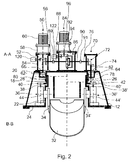
vertical rotation axis. The chute is suspended to the suspension rotor so that
it
rotates with the latter for circumferential distribution of charge material.
Furthermore, in the device according to US 3,693,812, the chute is suspended
to
be pivotally adjustable about a substantially horizontal axis for radial
distribution of
charge material. The suspension rotor and the adjustment rotor are driven by a
differential drive unit that is equipped with a main rotation drive, namely an
electric
motor, and an adjustment drive, namely an electric motor. The latter allows
creating differential rotation between the suspension rotor and the adjustment
rotor. In the device according to US 3,693,812, a pivoting mechanism is
provided
for adjustment of the chute. This mechanism, which is connected to the chute
and
actuated by the adjustment rotor, transforms a variation in angular
displacement
between the suspension rotor and the adjustment rotor due to differential
rotation
into a variation of the pivotal position i.e. the tilt angle of the chute.
[0003] The device for distributing charge material according to US 3,693,812
is
equipped with a compact drive unit for driving the two rotors. This unit is
enclosed
in a casing arranged on the main housing that supports the rotors and the
chute.
The casing has a primary input shaft; a secondary input shaft; a first output
shaft,
hereinafter called rotation shaft; and a second output shaft, hereinafter
called
adjustment shaft. The primary input shaft is driven by the main rotation
drive.
CA 02763131 2011-11-22
WO 2010/139776 PCT/EP2010/057805
2
Inside the casing, a reduction mechanism connects the primary input shaft to
the
rotation shaft, which extends vertically inside the main housing where it is
provided
with a gearwheel that meshes with a gear ring of the suspension rotor. The
adjustment shaft also extends vertically into the main housing where it is
provided
with a gearwheel that meshes with a gear ring of the adjustment rotor. Inside
the
casing of the drive unit, the rotation shaft and the adjustment shaft are
interconnected by means of an epicyclic differential mechanism, i.e. a sun-and-
planet gear train. The latter mainly comprises a horizontal annulus (ring
gear) that
has external teeth meshing with a gearwheel on the rotation shaft; a sun gear
that
is connected to the secondary input shaft; at least two planet gears that mesh
with
internal teeth of the annulus and with the sun gear. This sun-and-planet gear
train
is dimensioned so that the rotation shaft and the adjustment shaft have the
same
rotational speed imparted by the main rotation drive when the secondary input
shaft is stationary, i.e. when the adjustment drive is at stop. The adjustment
drive
is a reversible drive and connected to the secondary input shaft. By virtue of
the
differential mechanism, the adjustment drive allows driving the adjustment
shaft at
a faster and at a lower rotational speed than the rotation shaft to thereby
produce
a relative i.e. differential rotation between the suspension rotor and the
adjustment
rotor. The pivoting mechanism transforms such differential rotation into
pivoting
motion of the chute. A similar compact drive unit is disclosed in US patent
3,814,403 which mainly differs in that its two output shafts are coaxially
arranged,
with the adjustment shaft passing coaxially through the rotation shaft and
both
extending into the main housing through the same opening.
[0004] As will be appreciated, the above-described compact drive unit is a key
component of the device for distributing charge material. Since it is custom
made,
it represents a significant part of the total cost of the device. Moreover, in
order to
ensure continuous operation of the furnace when the drive unit requires
servicing
or major repair, a complete replacement unit is typically kept in stock by the
furnace operator.
Technical problem
[0005] It is a first object of the present invention to provide a device for
distributing charge material in a shaft furnace the maintenance of which is
CA 02763131 2011-11-22
WO 2010/139776 PCT/EP2010/057805
3
simplified and less cost-intensive. This object is achieved by a device
according to
claim 1.
General Description of the Invention
[0006] The device for distributing charge material according to the invention
comprises in a manner known per se: a main housing and a distribution chute
for
distributing charge material. A suspension rotor is mounted in the main
housing
and rotatable about a substantially vertical rotation axis, which typically
coincides
with the furnace axis. The suspension rotor is provided with a first gear ring
for
imparting rotation to this rotor. An adjustment rotor is mounted in the
housing and
rotatable about a substantially vertical rotation axis, which typically
coincides with
the rotation axis or the chute suspension rotor. For being driven, the
adjustment
rotor has a second gear ring. The distribution chute is suspended to the
suspension rotor so as to rotate therewith for circumferential distribution of
charge
material. Furthermore, for radial distribution of charge material, the chute
is
adjustable in orientation relative to the suspension rotor, in particular
pivotally
adjustable about a substantially horizontal pivoting axis, by means of the
adjustment rotor. A differential mechanism, in particular a differential gear,
interconnects both rotors in a manner that allows differential rotation of the
adjustment rotor relative to the suspension rotor. A main rotation drive,
typically an
electric motor, is connected to the suspension rotor for imparting rotation
thereto.
The latter drive is also connected, by way of the differential, to the
adjustment rotor
for imparting rotation to the latter. Furthermore, the device includes an
adjustment
drive, in particular an electric motor, that is connected through the
differential to
the adjustment rotor for imparting a differential rotation to the adjustment
rotor, i.e.
a variation in angular position of the adjustment rotor relative to the
suspension
rotor. This differential is configured to transmit to the adjustment rotor the
same
speed of rotation that the main rotation drive imparts directly to the
suspension
rotor unless the adjustment drive is operated to impart differential rotation
to the
adjustment rotor. In other words, the differential is configured to
superimpose
torque imparted by both drives respectively onto the adjustment rotor to allow
the
latter, as desired, to rotate in both senses or to keep its angular position
relative
the suspension rotor.
CA 02763131 2011-11-22
WO 2010/139776 PCT/EP2010/057805
4
[0007] According to the presently claimed invention, and in order to achieve
its
first object, the distribution device comprises three distinct casings
arranged on the
main housing. More specifically, the device comprises:
- a first casing arranged on the main housing and enclosing an angular
transmission, e.g. a bevel gear pair, between a substantially vertical output
shaft, which protrudes from the first casing into the main housing and is
operationally connected to drive a gearwheel that meshes with the first gear
ring of the suspension rotor to impart rotation to the latter, and a
connecting
shaft, which protrudes from the first casing at an angle, in particular
perpendicularly, with respect to the output shaft;
- a second casing arranged on the main housing and enclosing an angular
transmission, e.g. a bevel gear pair, between a substantially vertical output
shaft, which protrudes from the second casing into the main housing and is
operationally connected to drive a gearwheel that meshes with the second
gear ring of the adjustment rotor to impart rotation to the latter, and a
connecting shaft, which protrudes from the second casing at an angle, in
particular perpendicularly, with respect to the output shaft;
- a separate third casing that is spaced apart from the first and second
casings, e.g. on the main housing or on a separate support structure, and
encloses the differential, the differential being connected to a first shaft,
which protrudes from the third casing and is coupled to the connecting shaft
of the first casing, and to a second shaft, which protrudes from the third
casing and is coupled to the connecting shaft of the second casing.
[0008] As will be appreciated, the three separate casings with their
respective
integrated mechanisms can be designed as "standardized" units, manufactured
mainly with readily available mechanical components. Moreover, as first and
second casings, commercially available components that provide enclosed
angular transmissions may be used for transmitting driving torque to the first
and
second gear rings respectively. Thereby, the cost of the drive unit can be
reduced.
Moreover, each of the separate casings can be easily removed and individually
replaced, whereby maintenance is facilitated. In addition, in case of a
failure of the
differential in the third casing, the latter can be easily removed for
servicing, and
CA 02763131 2011-11-22
WO 2010/139776 PCT/EP2010/057805
the connecting shafts of the first and second casings connected by a direct
(non-
differential) torque transmission, e.g. in the form of a rigid shaft.
Accordingly, the
device can temporarily operate with a fixed position of the chute relative to
the
suspension rotor until the differential is repaired and reinstalled.
[0009] In a preferred embodiment, the adjustment drive is mounted to the third
casing and preferably connected to the differential by means of a reduction
gear,
which is beneficially arranged inside the third casing.
[0010] The main rotation drive may be mounted either to the third casing,
inside
of which its is preferably connected to the first shaft of the differential by
means of
a gear train; or to the first casing, inside of which it is preferably
connected to the
output shaft of the first casing by means of a gear train. The former
arrangement
allows designing both the first and second casings as identical units, thereby
further reducing cost and facilitating maintenance, whereas the latter
embodiment
facilitates continued operation in case the third casing is removed for
servicing or
repair of the differential mechanism.
[0011] Preferably, each of the first and second casings comprises a base plate
with a sealing bushing through which its output shaft protrudes. In this
embodiment, the main housing beneficially comprises, for each of the first and
second casings, a respective opening for the passage of the gearwheel on the
respective output shaft. This embodiment enables the need to manually remove
and reinstall the driving gearwheels in case of replacement of either of the
casings.
[0012] In order to increase positioning flexibility and tolerance regarding
minor
misplacement or improper orientation, wherein the first shaft of the
differential is
preferably coupled to the connecting shaft of the first casing by means of a
homokinetic universal joint arrangement. In addition or alternatively, the
second
shaft can be coupled to the connecting shaft of the second casing by means of
a
homokinetic universal joint arrangement. Preferably, the homokinetic universal
joint arrangement consists of a double Cardan shaft with length compensation,
e.g. through a length-extensible intermediate shaft. In order to further
increase
tolerance in orientation between the shafts, each of the two Cardan joints of
the
Cardan shaft is preferably a centered double Cardan joint.
CA 02763131 2011-11-22
WO 2010/139776 PCT/EP2010/057805
6
[0013] In a preferred configuration, which minimizes the intervention time for
continued operation in case of removal of the third casing, the main rotation
drive
is mounted on the first casing and the first casing and the second casing are
arranged on the main housing so that their connecting shafts are aligned. In
this
configuration, the third casing can simply be replaced by a rigid torque
transmission link.
[0014] Preferably, the differential gear is an epicyclic sun-and-planet gear
that
comprises an annulus, a sun gear and a planet gear carrier carrying at least
two
planet gears that mesh with the annulus and the sun gear. While other
configurations are not excluded, in a preferred configuration, the sun gear is
fixed
to the first shaft of the differential, the planet gear carrier is fixed to
the second
shaft of the differential, and the annulus is connected to the adjustment
drive and
rotatably supported, e.g. by the first shaft or by the second shaft.
[0015] In a typical configuration, the distribution device includes a pivoting
device that connects the distribution chute to the adjustment rotor. Such
pivoting
device is designed to transform a differential rotation of the adjustment
rotor
relative to the suspension rotor into a variation of the angle of inclination
of the
chute.
[0016] As will be understood, the device according to the invention is
designed
particularly for use in a shaft furnace charging installation. Accordingly, a
main
industrial application is e.g. in a metallurgical blast furnace for pig iron
production.
Brief Description of the Drawings
[0017] Further details and advantages of the present invention will be
apparent
from the following detailed description of several not limiting embodiments
with
reference to the attached drawings, wherein:
FIG.1 is a plan view of a device for distributing charge material into a shaft
furnace
according to a first embodiment of the invention;
FIG.2 is a vertical cross-sectional view of the device of FIG.1, composed of
an
upper part of the figure taken along section line A-A of FIG.1 and a lower
part
taken along section line B-B of FIG.1;
CA 02763131 2011-11-22
WO 2010/139776 PCT/EP2010/057805
7
FIG.3 is a view in side elevation, illustrating a differential mechanism, more
specifically a planetary gear for use in the device of FIG.1;
FIG.4 is a plan view of a device for distributing charge material into a shaft
furnace
according to a second embodiment of the invention;
FIG.5 is a vertical cross-sectional view of the device of FIG.4, composed of
an
upper part of the figure taken along section line C-C of FIG.4 and a lower
part
taken along section line D-D of FIG.4;
FIG.6 is a partial vertical cross-sectional similar to FIG.5, illustrating a
first
alternative embodiment of a differential gear;
FIG.7 is a partial vertical cross-sectional similar to FIG.5, illustrating a
second
alternative embodiment of a differential gear;
FIG.8 is a partial vertical cross-sectional similar to FIG.5, illustrating a
third
alternative embodiment of a differential gear;
FIG.9 is a partial vertical cross-sectional similar to FIG.5, illustrating a
fourth
alternative embodiment of a differential gear;
FIG.10 is a plan view of a device for distributing charge material into a
shaft
furnace according to a third embodiment of the invention;
FIG.11 is a vertical cross-sectional view of an upper part of the device of
FIG.10
taken along section line E-E of FIG.10;
FIG.12 is a plan view of a device for distributing charge material into a
shaft
furnace according to a fourth embodiment of the invention;
FIG.13 is a side elevation view of the device of FIG.12.
[0018] In these drawings, identical reference signs identify identical or
similar
parts, while reference signs with incremented hundreds digit identify
functionally
similar parts in a structurally different embodiment.
Detailed Description with respect to the Drawings
[0019] FIGS.1-2 illustrate a first embodiment of a device 10 for distributing
bulk
charge material ("burden") into a shaft furnace, especially onto the stockline
of a
blast furnace. The device 10 is designed to be part of a charging
installation, which
CA 02763131 2011-11-22
WO 2010/139776 PCT/EP2010/057805
8
is not shown in its entirety. It comprises a main housing 12 to be arranged on
the
furnace throat and which includes a fixed feeding spout 14 that defines a
vertical
feeding channel 16. A suspension rotor 18 is suspended inside the main housing
12 by means of a first large-diameter annular roller bearing 20 to be
rotatable
about a substantially vertical rotation axis. The suspension rotor 18
comprises a
generally cylindrical body provided at its lower in with a disk-shaped
horizontal
protection flange 24, which forms a screen between the interior of the main
housing 12 and the interior of the furnace. A second rotor, hereinafter called
adjustment rotor 26, surrounds the suspension rotor 18 and is suspended inside
the main housing 12 by means of a second large-diameter annular roller bearing
28, which is arranged so that the axis of rotation of the adjustment rotor 26
is
substantially coaxial to the axis of rotation of the suspension rotor 18.
[0020] Reference sign 32 identifies a distribution chute for bulk material fed
through the feeding channel 16. The chute 32 has two lateral suspension arms
34,
34' by means of which it is suspended to the suspension rotor 18. A pivoting
device that is actuated by the adjustment rotor 26 allows adjusting the
orientation
of the chute 32 relative to the suspension rotor 18, more specifically the
pivotal
position or tilting angle of the chute about an axis that is substantially
horizontal.
To this effect, the pivoting device connects the distribution chute 32 to the
adjustment rotor 26 to transform a differential rotation of the adjustment
rotor 26
into a variation of the pivotal position of the chute 32. In the illustrated
device 10,
the pivoting device comprises, for each suspension arm 34, 34' of the chute
32, a
pivoting mechanism 36, 36', which are carried at diametrically opposite
locations
on and by the suspension rotor 18. Each of the pivoting mechanisms 36, 36' has
a
respective vertical input shaft 38, 38', an internal gear system (not shown)
and a
horizontal suspension trunnion 44, 44'. The input shafts 38, 38' are parallel
to the
rotation axes of both rotors 18, 26 and connected to a respective gearwheel
40,
40' that meshes with a lower gear ring 42 of the adjustment rotor 26. Each
internal
gear system (not shown) transforms rotation of the respective input shaft 38,
38'
into rotation of the respective suspension trunnion 44, 44'. As will be noted,
both
pivoting mechanisms 36, 36' are symmetrical with respect to a center plane of
the
chute 32, that is to say, rotation of the input shafts 38, 38' by the lower
gear ring
42 of the adjustment rotor 26 results in a rotation in opposite senses (seen
from
CA 02763131 2011-11-22
WO 2010/139776 PCT/EP2010/057805
9
the median plane) of both suspension trunnions 44, 44' to pivot the chute 32.
As
seen in FIG.2, the lateral suspension arms 34, 34' are mounted to the
trunnions
44, 44' so that they define a substantially horizontal pivoting axis for the
chute 32.
[0021] As will be understood, other suitable adjustment mechanisms may be
used for adjusting the chute position relative to the suspension rotor 18. For
instance, U.S. patent no. 4,941,792 discloses a pivoting mechanism with a
forked
pivoting lever connecting two suspension trunnions to the adjustment rotor,
respectively an annular toothed segment that cooperates with an toothed sector
fixed to either of the two chute trunnions. U.S. patent no. 5,002,806 on the
other
hand proposes connecting the adjustment rotor to a crank on one of the chute
trunnions by means of a rod linkage with spherical joints. Whereas the above
adjustment mechanisms are designed to transform a differential rotation of the
adjustment rotor relative to the suspension rotor into a variation of the tilt
angle of
the chute, other possibilities of adjustment are not excluded. In a further
alternative
embodiment for instance, the chute is not a pivotable chute, but a sort of two-
piece
chute having an upper part, which is formed by and rotates in unison with the
suspension rotor about the furnace central axis, and a lower part, which
rotates
about a second vertical rotation axis that is laterally offset from the
central axis.
Examples of such distribution devices and corresponding adjustment mechanisms
for actuating the lower part of the two-part chute are disclosed in Japanese
patent
application Nos. JP 63 096205 or JP 02 022409 or in Soviet Union Inventor's
Certificate SU 1669988.
[0022] In FIGS.1-2, reference sign 50 identifies a first casing that is
arranged on
the main housing 12. The first casing 50 encases an angular transmission 52 of
the bevel gear type. The angular transmission 52 connects a substantially
vertical
output shaft 54 that protrudes from the casing 50 down into the main housing
12
and a substantially horizontal connecting shaft 56 that protrudes from the
first
casing 50 at a right angle with respect to the output shaft 54. In the
embodiment of
FIG.2, the upper end of the output shaft 54 is connected, through a gear train
58,
e.g. a reduction gear, to a main rotation drive 60, preferably an electric
motor while
other drives, such as hydraulic or pneumatic drives are not excluded. The
lower
end of the output shaft 54 is provided with a gearwheel 62 that meshes with a
first
CA 02763131 2011-11-22
WO 2010/139776 PCT/EP2010/057805
gear ring 64 on the suspension rotor 18. Accordingly, the output shaft 54 acts
as
rotation drive shaft to transmit torque from the main rotation drive 60 to the
suspension rotor 18. As will be noted, the output shaft 54 passes through a
sealing
bushing, e.g. a stuffing box, in the lower base plate of the casing 50, in
order to
isolate the interior of the casing 50 from the interior of the main housing
12.
Furthermore, the base plate of the casing 50 is removably mounted onto the
main
housing 12 using a suitable seal to seal an opening 66 in the top plate of the
main
housing 12. The opening 66 is dimensioned to permit passage of the gearwheel
62.
[0023] In FIGS.1-2, reference sign 70 identifies a second casing that is
arranged
on the main housing 12. This casing 70 also encloses an angular transmission
72
with a bevel gear pair. The angular transmission 72 connects a substantially
vertical output shaft 74 to a substantially horizontal connecting shaft 76.
The lower
end of the output shaft 74 carries a gearwheel 78 that meshes with a second
gear
ring 80 that is fixed to an upper region of the adjustment rotor 26, above the
lower
gear ring 42. The output shaft 74 protrudes into the main housing 12 through a
sealing bushing in the lower base plate of the casing 70 whereas the
connecting
shaft 76 protrudes horizontally from the casing 70 through a suitable bearing.
As
will be noted, the base plate of the casing 70 is also removably mounted onto
the
main housing 12 using a suitable seal to seal an opening 82 in the top plate
of the
main housing 12. The opening 82 is again dimensioned to permit passage of the
gearwheel 78.
[0024] In between the first casing 50 and the second casing 70, a third casing
84
is spaced apart on the main housing 12. The third casing 84 encloses a
differential
mechanism, in particular an epicyclic sun-and-planet gear 86. Three shafts are
connected to the sun-and-planet gear mechanism 86 and emerge from the third
casing 84. These are namely: (i) a substantially horizontal first shaft 88
that is
coupled, by means of a coupling 89, to the connecting shaft 56 of the first
casing
50; (ii) a substantially horizontal second shaft 90 that is coupled, by means
of a
coupling 91, to the connecting shaft 76 of the second casing 70; and (iii) a
drive
shaft 92 that is connected, through a reduction gear 94, to an adjustment
drive 96,
in particular an electric motor. Suitable couplings 89, 91 are torsionally
rigid
CA 02763131 2011-11-22
WO 2010/139776 PCT/EP2010/057805
11
compensating couplings, preferably flexible couplings, for instance Oldham-
couplings or positive-fit claw couplings, while any torque-transmitting, and
generally misalignment- and positioning-error-tolerant compensating coupling
may
be used. Another preferred choice for providing either of the yielding
couplings 89,
91 is a flexible disk coupling or a positive fit gear coupling, in particular
a gear
coupling of the type with curved external gear teeth engaging an internally
toothed
sleeve. More preferably each yielding coupling 89, 91 includes a sequence of
two
of the latter flexible disk or gear couplings so as to imitate a double Cardan
shaft.
[0025] The sun-and-planet gear mechanism 86 of the embodiment of FIG.1-2 is
shown in an enlarged side-elevation in FIG.3. It comprises an annulus 100
provided with a conical external bevel gearing 102 and a cylindrical epicyclic
internal gearing 104. A conical bevel gear 106 is fixed to the drive shaft 92
and
meshes the bevel gearing 102 of the annulus 100 to transmit driving torque
from
the adjustment drive 96 to the annulus 100. A sun gear 108 is fixed to and
supported by the first shaft 88 to bear coaxially inside the annulus 100.
Hence, the
sun gear 108 is coupled to the connecting shaft 56 of the first casing 50. Two
epicyclic planet gears 110' and 110" mesh with the internal gearing 104 of the
annulus 100 and, simultaneously, with a cylindrical epicyclic external gearing
of
the sun gear 108. The planet gears 110' and 110" are rotatably supported on a
planet gear carrier 112, which in turn is fixed to and supported by the second
shaft
90 that is coupled to the connecting shaft 76 of the second casing 70. As seen
in
FIG.2, the annulus 100 is rotatably supported by the second shaft 90.
[0026] The differential sun-and-planet gear mechanism 86 is dimensioned so
that the rotational speed N1 of the first shaft 88, imparted by the main
rotation
drive 60 via the angular transmission 52, is equal to the rotational speed N2
of the
second shaft 90, whenever the third shaft connected to the differential 86,
i.e. the
drive shaft 92 does not rotate, i.e. when the latter is at standstill (N3 =
0). In other
words, the differential 86 is configured to transmit to the adjustment rotor
26 the
same speed of rotation that is imparted to the suspension rotor 18 by the main
rotation drive 60, unless the adjustment drive 96 imparts torque to the drive
shaft
92 and thereby differential rotation to the adjustment rotor 26 relative to
the
suspension rotor 18. Accordingly, when the adjustment drive 96 is operated to
CA 02763131 2011-11-22
WO 2010/139776 PCT/EP2010/057805
12
rotate the drive shaft 92 at a rotational speed N3 (0 0) in a first sense, the
rotational speed N2 of the second shaft 90 will correspond to the addition of
the
rotational speed N1 of the first shaft 88 and the rotational speed N3 of the
drive
shaft 92 multiplied by an appropriate gear ratio (which depends on the design
of
the differential sun-and-planet gear mechanism 86). On the other hand, when
the
adjustment drive 96 rotates the drive shaft 92 at a rotational speed N3 (0 0)
in the
opposite sense, the rotational speed N2 of the second shaft 90 will correspond
to
the rotational speed N1 of the first shaft 88 reduced by (subtraction) the
rotational
speed N3 of the drive shaft 92 multiplied by the appropriate gear ratio. It
follows
that, by operating the adjustment drive 96 as desired, the differential sun-
and-
planet gear mechanism 86 allows increasing, reducing or eliminating an angular
displacement between the suspension rotor 18 and the adjustment rotor 26.
Accordingly, the differential 86 interconnects the suspension rotor 18 and the
adjustment rotor 26 in a manner that allows differential rotation of the
former
relative to the latter. On the other hand, the differential 86 allows
maintaining both
rotors 18, 26 at the same speed of rotation without operation of the
adjustment
drive 96, i.e. when the latter is at rest. Any suitable adjustment mechanism
as
described above then transforms variations in angular displacement between the
suspension rotor 18 and the adjustment rotor 26 into corresponding variation
of
the position of the chute 32, in particular the pivoting position / tilting
angle in case
of FIGS.1-2. As will be understood, the rotational speed of the adjustment
drive 96
determines the adjusting, i.e. pivoting speed of the chute 32. When the chute
32 is
to be maintained in position (relative to the suspension rotor 18), it
suffices to stop
the adjustment drive 96. Breaking of the adjustment drive can be achieved
electrically. After stop (rest) of the adjustment drive 96, the latter may be
blocked
in rotation mechanically, e.g. by means of a self-blocking configuration of
the
reduction gear 94. In the above functional description, it is assumed that the
gear
ratio between the first gear ring 64 and the gearwheel 62 is identical to the
gear
ratio between the second gear ring 80 and the gearwheel 78. In case the latter
gear ratios differ, the internal gear ratios of the differential sun-and-
planet gear
mechanism 86 are adapted accordingly to achieve synchronous rotation of the
rotors 18, 26 by sole action of the main rotation drive 60 and to permit
differential
rotation there between by action of the auxiliary adjustment drive 96.
CA 02763131 2011-11-22
WO 2010/139776 PCT/EP2010/057805
13
[0027] Turing back to FIG.2, reference sign 120 identifies a first rotary
encoder
that measures rotation of the output shaft 54 of the first casing 50, which -
by
applying the gear ratio between the gearwheel 62 and the first gear ring 64 -
is
equivalent to measuring rotation of the suspension rotor 18. A second rotary
encoder 122 measures rotation of the drive shaft 92, which - by applying
appropriate gear ratios for bevel gears 106, 102, for planetary gear 86, and
for the
gearwheel 78 and the second gear ring 80 - is equivalent to measuring rotation
of
the adjustment rotor 26. Using measurements made by the encoders 120, 122 and
knowledge of the gear ratios, the actual (pivotal) position of the chute 32
can be
determined accurately at any moment.
[0028] As will be appreciated, the three casings 50, 70, 84 form, with their
integrated transmission mechanisms, units which may be standardized and
manufactured using commercially available standard mechanical components.
Thereby, constructional cost of the distribution device 10 can be
significantly
reduced. Moreover, each casing 50, 70, 84 may be removed, replaced and
serviced individually. This obviously facilitates maintenance and repair
operations.
In particular, in case of a need of servicing or replacement of a sealing
bushing at
the level of either output shaft 54, 74, the relatively inexpensive first and
second
casings can be replaced separately, without removal of the differential 86.
Furthermore, in case of a failure of the differential 86 that is enclosed
separately in
the third casing 84, the latter may be removed without interruption of
operation of
the distribution chute 32, due to the alignment of the connecting shafts 56,
76 of
the first and second casings 50, 70 in the embodiment of FIG.1-3. Such
alignment
allows temporary installation of a rigid link to connect the compensating
couplings
89, 91. With the main rotation drive 60 being still operational on the first
casing 50,
this measure enables continued operation with the chute 32 having a fixed
pivotal
position until the differential 86 is installed again after repair or
servicing.
[0029] Turning now to FIGS.4-5, a second embodiment of a distribution device
210 will be described hereinafter. Features in the lower part of FIG.5, which
are
essentially identical to those described with respect to FIG.2, are identified
by
identical reference signs and will not be described again.
CA 02763131 2011-11-22
WO 2010/139776 PCT/EP2010/057805
14
[0030] The charging device 210 of FIGS.4-5 comprises a third casing 284 that
is
spaced apart from the first casing 250 and the second casing 270. The third
casing 284 is arranged on the main housing 12 approximately on the median
plane between the casings 250, 270 and laterally offset away from the furnace
central axis, i.e. the rotation axis of the rotors 18, 26. As opposed to the
preceding
embodiment, in the charging device 210 of FIGS.4-5, the first and second
shafts
288, 290, which are connected to the differential 286 in the third casing 284,
are
thus not aligned with the connecting shafts 256, 276 of the first and second
casings 250, 270.
[0031] To bridge the offset, the first and second shafts 288, 290 are coupled
to
the connecting shafts 256, 276 respectively, each by means of a suitable a
homokinetic universal joint arrangement as illustrated in FIGS.4-5. The latter
arrangements each comprise a double Cardan shaft 285, 287 with a first and a
second Cardan joint 293, 295 that are interconnected by means of an
intermediate
shaft 297, 297' (also called Universal joints; U-joints; Hooke's joints). In
each
double Cardan shaft, the first Cardan joint 293; 293' is phased in relation to
the
second Cardan joint 295; 295' to cancel the variations in angular velocity
inherent
to single Cardan joints. That is to say, the second Cardan joint 295; 295'
cancels
the velocity transmission errors introduced by the first Cardan joint 293;
293'. As
will be understood, the double Cardan shafts 285, 287 are to form a
homokinetic
coupling in order to ensure uniform material distribution by the chute 32 in
circumferential direction. The intermediate shafts 297, 297' are each
configured as
a telescopic length-extensible shaft in order to provided length compensation
and
thereby further increase positioning flexibility and orientation tolerance for
the
casings 250, 270, 284. To avoid a risk of improper angular orientation between
the
intermediate shaft 297 and the shafts 288, 256 connected thereto, respectively
between shaft 297' and the shafts 290, 276 connected thereto, each Cardan
joint
293, 293'; 295, 295' is preferably configured as centered double Cardan joint,
that
consists of two Hooke's joints mounted back to back so that each Cardan joint
293, 293'; 295, 295' itself acts as a homokinetic constant-velocity (CV)
joint.
Alternatively, actual constant-velocity (CV) joints (also called homokinetic
joints),
such as Rzeppa-joints or Tracta joints, may be used in the place of each
Cardan
joint 293, 293'; 295, 295'.
CA 02763131 2011-11-22
WO 2010/139776 PCT/EP2010/057805
[0032] The differential 286 of the second embodiment illustrated in FIG.5 is
of
substantially identical configuration than that of FIG.2. That is to say, it
comprises
an annulus 200 connected to the adjustment drive 296, which is however
rotatably
supported on the first shaft 288 in FIG.5, a sun gear 208 that is fixed to the
first
shaft 288, and a planet gear carrier 212 that is fixed to the second shaft
290. The
planet gears 210, 210' are arranged on the carrier 212 to revolve about the
sun
gear 208 and engage the internal gearing of the annulus 200 and the external
gearing of the sun gear 208. In the embodiment of FIGS.4-5 the adjustment
drive
296 is connected to drive the annulus 200 by means of a reduction gear 294 of
the
worm-gear type, which is preferably self-blocking and arranged inside the
third
casing 284. The reduction gear 294 is connected to a gearwheel that engages an
outer gearing of the annulus 200. Similarly, the gear train 258, which
connects the
main rotation drive 260 to the first shaft 288 of the differential 286, is
integrated
into the casing 284. The gear train 258 comprises a cylindrical gearwheel pair
with
a first large-diameter gearwheel fixed onto the first shaft 288 and a second
small-
diameter gearwheel fixed to the drive shaft of the main rotation drive 260.
Accordingly, in the embodiment of FIGS.4-5, the main rotation drive 260, alike
the
adjustment drive 296, is mounted to the third casing 284, whereby replacement
of
the first casing 250 is facilitated and its unit cost is reduced. Moreover,
this
arrangement allows designing the first and second casings 250, 270 as
identical
standardized units when compared to the embodiment of FIGS.1-2.
[0033] As further seen in FIG.5, each of the first and second casings 250; 270
comprises an angular transmission in the form of a bevel gear pair 223; 223'
to
transmit torque from the respective substantially horizontal connecting shaft
256;
276 to the respective substantially vertical output shaft 254; 274. As will be
appreciated, in the embodiment of FIGS.4-5, the first and second casings 250;
270, each comprise a base plate with a sealing bushing through which the
respective output shaft 254; 274 protrudes. Accordingly, the main housing 12
also
comprises, for each of these casings 250, 270, a respective opening
dimensioned
for the passage of the respective output gearwheel 62; 78. Accordingly, the
casings 250, 270 can be rapidly removed and reinstalled onto the top plate of
the
main housing, without the need for manual removal or reinstallation of the
output
gearwheels 62; 78.
CA 02763131 2011-11-22
WO 2010/139776 PCT/EP2010/057805
16
[0034] Whereas FIG.2 & FIG.5 illustrate preferred configurations of the
planetary
differential 86; 286 in the third casing 84; 284, alternative configurations
as
schematically illustrated in FIGS.6-9 are equally within the scope of the
invention.
These embodiments differ from that of FIG.5 only in the configuration of the
respective differential and the latter's connection to the drives 260, 294.
Other
features of FIGS.6-9 will therefore not be repeatedly described.
[0035] FIG.6 illustrates an alternative differential 386 in which the sun gear
308
is fixed to the second shaft 290 whereas the planet gear carrier 312 is fixed
to the
first shaft 288 of the mechanism 386. The annulus 300 in turn is connected to
the
adjustment drive 296 (see FIG.4) and rotatably supported by the second shaft
290
(whereas support on the first shaft 288 is equally possible). The annulus 300
comprises an additional external worm wheel engaging a worm on the drive shaft
292 of the adjustment drive 296 to form a reduction gear 394. In the variant
of
FIG.6, the gear train 358 for the main rotation drive 260 is also of the worm
gear
type with the worm wheel fixed to the first shaft 288 and the worm connected
the
drive shaft of the main rotation drive 260.
[0036] In the embodiment of FIG.7, the differential drive mechanism 486 is
also
an epicyclic sun-and-planet gear but has yet another configuration. Here, the
sun
gear 408 is connected to the adjustment drive 296 and rotatably supported by
the
second shaft 290. The planet gear carrier 412 is fixed to the second shaft 290
and
an annulus 400 devoid of external gearing is fixed to the first shaft. The sun
gear
408 thus has a central passage for the second shaft 290 as seen in FIG.7. The
reduction gear 494 for the adjustment drive 296 is similar to that of FIG.6,
except
that the worm wheel is provided on the specially designed sun gear 408. The
gear
train 458 for the main rotation drive 260 is identical to that used in the
embodiment
of FIG.5.
[0037] In the embodiment of FIG.8, a further variant of the epicyclic sun-and-
planet gear 586 has its sun gear 508 fixed to the second shaft 290, its planet
gear
carrier 512 connected to the adjustment drive 296 and rotatably supported by
the
second shaft 290; and its said annulus 500 is fixed to the first shaft 288.
The
reduction gear 594 for the adjustment drive 296 is similar to that of FIGS.5-
6,
except that the worm wheel is provided on the planet gear carrier 512. The
gear
CA 02763131 2011-11-22
WO 2010/139776 PCT/EP2010/057805
17
train 558 for the main rotation drive 260 is identical to that of FIG.5 and
FIG.7. In
the embodiment of FIG.9, the epicyclic sun-and-planet gear 686 is
substantially
identical to that of FIG.8. In this embodiment however, the annulus 600 is
provided
with an external gearing to form a gear train 658 for the main rotation drive
260
together with a gearwheel connected to the drive shaft of the drive 260.
[0038] Irrespective of the chosen configuration, the differential, which is
preferably an epicyclic planetary gear, interconnects the suspension rotor to
the
adjustment rotor while allowing differential rotation there between. More
specifically, the differential is to be configured to transmit to the
adjustment rotor
26 the same speed of rotation imparted to the suspension rotor 18 by the main
rotation drive 260 unless the adjustment drive 296 imparts differential
rotation to
the adjustment rotor 26 for adjusting, e.g. pivoting the chute.
[0039] Although not illustrated in FIGS.4-9 it will be understood, that the
first
casing 250 is preferably provided with an auxiliary coupling for coupling the
main
rotation drive 260 to its output shaft 254 in case the third casing 284 has to
be
removed for repair or servicing. Accordingly, the device 210 may also
temporarily
continue to operate with a fixed adjustment position of the chute 32 by
connecting
a rigid link, e.g. a shaft, in between the connecting shafts 256, 276.
[0040] Finally, it remains to be noted that a combination of the first and
second
casing designs according to FIGS.1-3 with a generally offset third casing, and
one
or two homokinetic universal joint arrangements connecting one or both
connecting shafts to the differential is also within the scope of the
invention. Such
combination allows temporary operation without a differential, i.e. with fixed
chute
adjustment, while at the same time providing additional freedom and tolerance
in
positioning the three casings.
[0041] In the following description of third and fourth embodiment of the
invention, only the main differences with respect to the first and second
embodiments of FIG.1-3 and FIG.4-5 will be detailed.
[0042] With respect to FIGS.1-3 and FIG.4-5, the embodiment of FIGS.10-11
generally corresponds to a combination employing a single homokinetic
universal
joint arrangement as shown in FIGS.4-5, e.g. between the first and third
casings
250; 284, and a simpler flexible compensating coupling as shown in FIG.2, e.g.
CA 02763131 2011-11-22
WO 2010/139776 PCT/EP2010/057805
18
between the second and third casings 270, 284. FIGS.10-11 schematically
illustrate a distribution device 310 according to such a third embodiment.
[0043] In the distribution device 310 of FIGS.10-11, the connecting shaft 356
of
the first casing 350 is coupled to the first shaft 388 of the differential
786, which is
arranged in the separate third casing 384, by means of a double Cardan shaft
385,
which is configured as described above. The connecting shaft 376 of the second
casing 370 however is connected to the second shaft 390 of the differential
786 by
means of a simpler compensating coupling 399, e.g. a jaw coupling, an Oldham
coupling, a flexible disk coupling or a gear coupling, for compensating minor
radial,
axial and/or angular mismatch between the shafts 376, 390. Accordingly, the
connecting shaft 376 on the second casing 370 and the second shaft 390 of the
differential 786 are substantially, though not necessarily exactly coaxial.
Such
alignment is achieved e.g. by appropriate orientation of the third casing 384
and of
the bearing of the connecting shaft 376 in the second casing 370. Similar to
the
embodiment of FIG.2, the main rotation drive 360 in the embodiment of FIGS.10-
11 is supported on the first casing 350. Accordingly, the first casing 350
encloses
a gear train 358 connecting the main drive 360, through the angular
transmission
352, to the output shaft 354. For temporarily continuing operation (at a fixed
tilting
angle of the chute 32) in case of removal of the third casing 370, e.g. for
servicing
the differential 786, the connecting shafts 356, 376 can be interconnected
directly
by means of an auxiliary double Cardan shaft (not shown) of greater length.
The
second casing 370 in turn encloses only the angular transmission 372
connecting
the connecting shaft 376 to the output shaft 374. The differential 786 shown
in
FIGS.10-11 is substantially identical to that described with respect to FIG.5
(except that the annulus is carried by the second shaft 390). The embodiment
of
FIGS.10-11 has the advantage of providing an increase in positioning
flexibility
and tolerance regarding minor misplacement or improper orientation comparable
to FIG.4-5 without using two double Cardan shaft arrangements.
[0044] FIGS.12-13 illustrate a fourth embodiment of a charging device 410. As
seen in FIGS.12-13, the third casing 484 of this embodiment is arranged
laterally
at a distance from the main housing 12 and supported on a separate support
structure 483, i.e. the third casing 484 is supported independently of the
main
CA 02763131 2011-11-22
WO 2010/139776 PCT/EP2010/057805
19
housing 12, e.g. by the blast furnace top cone or by the steel support
structure of
the blast furnace. The connecting shafts 456, 476 of the first and second
casings
450, 470 are each respectively connected to the first and second shafts 488,
490
of the third casing 484 by means of a corresponding double Cardan shaft 485,
487. The first and second casings 450, 470 have a compact and modular
interchangeable configuration since they enclose only the respective angular
transmission (not shown). As seen in the partially sectioned plan view of
FIG.12,
the configuration of the differential 886 and gear components enclosed in the
third
casing 484 substantially corresponds to that of FIG.7. The sun gear 808 is
driven
by the adjustment drive 496, the annulus 800 is driven, through the gear train
458
that drives the first shaft 488, by the main rotation drive 460 whereas the
planet
gear carrier 812 drives the second shaft 490 either differentially for
adjusting the
chute 32 or synchronously for maintaining the chute 32 in position. The drives
460,
496 are both supported by the third casing 484. As will be appreciated, the
embodiment of FIGS.12-13 saves constructional space immediately above the
main housing 12 and further facilitates access to the separate third casing
484 for
maintenance purposes. Accordingly, as will be understood, variants of the
embodiments of FIGS.1-3, 4-5, or 10-11, in which the third casing is spaced
apart
and arranged on a separate support independently of the main housing 12 are
also within the scope of the present invention.
CA 02763131 2011-11-22
WO 2010/139776 PCT/EP2010/057805
Legend: 90 second shaft
92 drive shaft / third shaft
FIG.1-3 94 reduction gear (at 84)
10 distribution device 96 adjustment drive
12 main housing 100 annulus (of 86)
14 feeding spout 102 external bevel gearing (of 100)
16 feeding channel 104 internal gearing (of 100)
18 suspension rotor 106 bevel gear (on 92)
20 roller bearing 108 sun gear (of 86)
24 protection flange 110'; planet gears (of 86)
26 adjustment rotor 110"
28 roller bearing 112 planet gear carrier (of 86)
32 distribution chute 120; rotary encoders
122
34, 34' suspension arms
FIG.4-5
36, 36' pivoting mechanism
210 distribution device
38, 38' input shafts (of 36, 36')
250 first casing
44, 44' suspension trunnions
270 second casing
40, 40' gearwheel (of 38, 38')
284 third casing
42 lower gear ring
286 differential gear
50 first casing
288 first shaft (of 286)
52 angular transmission (at 50)
290 second shaft (of 286)
54 output shaft (at 50)
256 connecting shaft (of 250)
56 connecting shaft (at 50)
276 connecting shaft (of 270)
58 gear train (at 50)
285, double Cardan shafts
60 main rotation drive (at 50) 287
62 gearwheel (of 54) 293, first Cardan joint
64 first gear ring (on 18) 293'
66 opening (in 12, at 50) 295, second Cardan joint
295'
70 second casing
297, intermediate shaft
72 angular transmission (at 70) 297'
74 output shaft (at 70) 200 annulus (of 286)
76 connecting shaft (at 70) 208 sun gear (of 286)
78 gearwheel (of 74) 210'; planet gears (of 286)
80 second gear ring (on 26) 210"
82 opening (in 12, at 70) 212 planet gear carrier (of 286)
84 third casing 294 reduction gear (for 296)
86 differential gear 296 adjustment drive
88 first shaft 258 gear train (for 260)
89; 91 coupling 260 main rotation drive (at 284)
CA 02763131 2011-11-22
WO 2010/139776 PCT/EP2010/057805
21
223; bevel gear pairs 360 main rotation drive
223'
370 second casing
FIG.6 372 angular transmission (at 370)
300 annulus (of 386) 374 output shaft (at 370)
308 sun gear (of 386)
384 third casing
310'; planet gears (of 386) 388 first shaft (of 786)
310"
312 planet gear carrier (of 386) 390 second shaft (of 786)
394 reduction gear (for 296) 356 connecting shaft (of 350)
358 gear train (for 260) 376 connecting shaft (of 370)
FIG.7 385 double Cardan shaft
400 annulus (of 486) 396 adjustment drive
408 sun gear (of 486) 399 compensating coupling
410'; planet gears (of 486) 794 reduction gear
410" 786 differential gear
412 planet gear carrier (of 486) FIG.12-13
494 reduction gear (for 296) 410 distribution device
458 gear train (for 260) 450 first casing
FIG.8 456 connecting shaft (of 450)
500 annulus (of 586) 458 gear train (for 460)
508 sun gear (of 586)
460 main rotation drive
510'; planet gears (of 586)
510" 470 second casing
512 planet gear carrier (of 586) 476 connecting shaft (of 470)
594 reduction gear (for 296)
483 support structure
558 gear train (for 260)
FIG.9 484 third casing
600 annulus (of 686) 488 first shaft (of 786)
608 sun gear (of 686) 490 second shaft (of 786)
610'; planet gears (of 686)
610" 485; double Cardan shafts
612 planet gear carrier (of 686) 487
694 reduction gear (for 296) 496 adjustment drive
668 gear train (for 260)
FIG.10-11 886 differential gear
310 distribution device 800 annulus (of 886)
350 first casing 808 sun gear (of 886)
352 angular transmission (at 350)
354 output shaft (at 350) 812 planet gear carrier 812 (of 886)
358 gear train (for 360)