Note : Les descriptions sont présentées dans la langue officielle dans laquelle elles ont été soumises.
CA 02763390 2016-06-13
SOLID STATE FLEXURE FOR POINTING DEVICE
BACKGROUND OF THE INVENTION
[0002] Many systems depend on the accurate and durable angular
alignment of
components. For example, a military training system may simulate a combat
environment
using optical emitters such as lasers mounted to simulated weapons, and
sensors on various
targets to register when laser light hits the targets, indicating accurate
fire. In order to ensure
effective training, it is required that the lasers "point" or accurately be
boresighted in the
direction an actual or simulated weapon would fire. Because of variations in
the
manufacture of lasers such as vertical cavity surface emitting lasers
(VCSELs), adjustment
of the laser alignment is often necessary to achieve accurate boresighting.
[0003] Military training is also an example of an environment in
which alignments
may be difficult to maintain. Lasers and other equipment may undergo intense
shock and
vibration, and mounting and alignment systems for the lasers should maintain
proper
alignment even when subjected to such treatment. Even in less demanding
environments, the
alignment process should be easy to accomplish and stable once achieved. For
example,
laboratory optical experiments may be facilitated when laser alignment is
simple and
reliable, reducing alignment time and minimizing production and testing costs.
[0004] Previous alignment systems have been complex, expensive, and
prone to
misalignment in dynamic environments. One particular prior system uses a pair
of wedge-
shaped prisms, called Risley prisms, placed sequentially in the path of a
laser. The prisms
may be rotated independently about the optical axis of the laser. Rotating the
prisms with
respect to each other changes the net overall deflection of the beam, and
rotating the prisms
as a pair changes the direction in rotation in which the deflection takes
place, so that the
beam may be aimed in any direction within a small solid angle about the
nominal laser axis.
Such a system has several moving parts, including the prisms and elements for
actuating the
1
CA 02763390 2016-06-13
prisms. The prisms introduce four optical surfaces into the optical path,
which result in loss
of signal in the system, as well as produce stray reflections. The surfaces of
the prisms may
become dirty, cloud up due to condensation, or otherwise lose transparency due
to
environmental effects. Shock and vibration control is harder to achieve when
multiple parts
are included in an assembly. Misalignment and breakdown will often occur.
[0005] There is accordingly a need for an angular alignment device
that is
mechanically simple and reliable, and alleviates the above problems.
BRIEF SUMMARY OF THE INVENTION
[0006] Accordingly, there is described a system for achieving multi-axis
angular
adjustment of devices, the monolithic mount comprising: four threaded
actuating screws;
and a monolithic mount including: first, second, and third generally tubular
sections
sequentially arranged along a longitudinal axis and surrounding a bore that
passes through
all three sections, the bore through the first section defining the
longitudinal axis of the
monolithic mount; a first set of two flexures flexibly connecting the first
and second
sections, the two flexures in the first set positioned on opposing sides of
the bore and
constraining the second section to rotate with respect to the first section in
a first rotational
degree of freedom transverse to the bore; a second set of two flexures
flexibly connecting
the second and third sections, the two flexures in the second set positioned
on opposing
sides of the bore and constraining the third section to rotate with respect to
the second
section in a second rotational degree of freedom transverse to the bore, the
first and second
rotational degrees of freedom being different; four threaded holes in the
first section for
receiving the four threaded actuating screws for rotating the second and third
sections with
respect to the first section, the four threaded holes being parallel to the
longitudinal axis of
the mount; four bearing surfaces on an end face of the third section, each
bearing surface
configured to receive an end of one of the four threaded actuating screws; and
four passages
in the second section for enabling the four actuating screws to reach the
third section without
engaging the second section.
2
CA 02763390 2016-06-13
[0007] In some embodiments, the first and second rotational degrees
of freedom are
orthogonal to each other.
[0009] In some embodiments, the first section is of a larger
dimension than the second
and third sections in a direction transverse to the longitudinal axis such
that a shoulder is
formed on the first section. The shoulder is configured for receiving a
fastener for affixing
the monolithic mount to another structure. The mount may include a pin
extending from the
shoulder and parallel to the longitudinal axis, the pin configured for
engaging a hole in the
panel for rotationally aligning the monolithic mount in the hole.
[0010] In another embodiment, there is described a system for
achieving multi-axis
angular adjustment of devices, the system comprising: four actuating screws;
and a
monolithic mount including: first, second, and third generally tubular
sections sequentially
arranged along a longitudinal axis and surrounding a bore that passes through
all three
sections, the bore defining the longitudinal axis of the monolithic mount; a
first set of two
flexures flexibly connecting the first and second sections, the two flexures
in the first set
positioned on opposing sides of the bore and constraining the second section
to rotate with
respect to the first section in a first rotational degree of freedom
transverse to the bore; a
second set of two flexures flexibly connecting the second and third sections,
the two flexures
in the second set positioned on opposing sides of the bore and constraining
the third section
to rotate with respect to the second section in a second rotational degree of
freedom
transverse to the bore, the first and second rotational degrees of freedom
being different;
four threaded holes through the first section for receiving the four actuating
screws for
rotating the second and third sections with respect to the first section, each
of the four
threaded holes parallel to the longitudinal axis of the monolithic mount and
wherein one of
the four actuating screws is threaded into each of the four threaded holes;
two bearing
surfaces on an end face of the second section and two bearing surfaces on an
end face of the
third section, each bearing surface configured to receive an end of one of the
four actuating
screws; and two passages in the second section for enabling two of the four
actuating screws
to reach the third section without engaging the second section.
100111 The system may further include a device aligned by the system.
The device
aligned by the system may be an optical device. The device aligned by the
system may emit
3
CA 02763390 2016-06-13
light. The device aligned by the system may be a laser, and the alignment may
adjust the
aiming of the laser. The device aligned by the system may be a sensor.
BRIEF DESCRIPTION OF THE DRAWINGS
[0012] Figures 1A and 1B illustrate perspective views of an alignment
system
according to an embodiment of the invention.
[0013] Figures 2A and 2B show front and rear perspective views of a
monolithic
mount according to an embodiment of the invention.
[0014] Figure 3 shows an orthogonal view of the monolithic mount of
Figure 2A, as
seen from direction A-A shown in Figure 2A.
[0015] Figure 4 shows a cross-section view of the monolithic mount of
Figure 2A,
taken through section C-C shown in Figure 3.
[0016] Figure 5 shows an orthogonal view of the monolithic mount of
Figure 2A, as
seen from direction B-B shown in Figure 2A.
[0017] Figure 6 shows a cross-section view of the monolithic mount of
Figure 2A,
taken through section D-D shown in Figure 5.
[0018] Figure 7 shows the monolithic mount of Figure 2A, with
actuating screws in
place.
[0019] Figure 8 shows a monolithic mount in accordance with a second
embodiment.
[0020] Figure 9 shows the monolithic mount of Figure 8, with actuating
screws in
place.
[0021] Figure 10 illustrates a clocking feature in the form of pin.
[0022] Figure 11 illustrates a perspective view of a monolithic
mount, in accordance
with another embodiment.
4
CA 02763390 2011-11-24
WO 2010/138317
PCT/US2010/034879
DETAILED DESCRIPTION OF THE INVENTION
[0023] Figures 1A and 1B illustrate perspective views of an alignment system
100 according
to an embodiment of the invention. The system comprises a monolithic mount
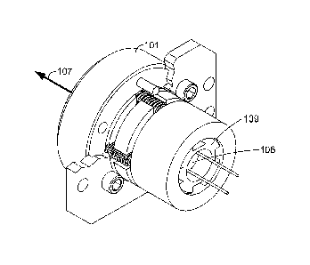
101, four
actuating screws 102-105, and a semiconductor laser 106. The structure of
monolithic mount
101 will be described in more detail below. In use, example system 100 allows
the adjustment of
the aim of laser beam 107 in two orthogonal angular degrees of freedom Gx and
Gy by simply
turning screws 102-105 in a suitable sequence. Laser beam 107 is emitted
through bore 108.
The system is suitable for panel mounting, as is shown in Figure 1B, and the
angular adjustment
can be accomplished from one side of the panel. Laser 106 may be, for example,
packaged in a
standard TO-style package that is retained in mount 101 by retainer 109, but
other kinds of
attachments are possible. For example, a laser or other element may be
attached to mount 101
using an adhesive, a clamp, a press fit, threads, one or more fasteners, or by
some other means.
[0024] Figures 2A and 2B show front and rear perspective views of monolithic
mount 100.
Bore 108 defines a longitudinal axis 204 of mount 101. Mount 101 comprises
three main
sections 201, 202, and 203, arranged sequentially along longitudinal axis 204,
with second
section 202 residing between first section 201 and third section 203. The
sections 201, 202, and
203 are generally tubular, and while they are shown as cylindrical in the
Figures, this is not a
requirement. For example, the sections may have any suitable cross-sectional
shape, including
round, oval, square, polygonal, or another shape. Monolithic mount 101 may be
fabricated by
any suitable process, from any suitable material. In one embodiment, mount 101
is machined
from 303 stainless steel, but other processes and materials are possible. For
example, mount 101
may be machined from another material such as aluminum, acetal, or another
metal or plastic, or
may be made from a molded polymer such as acetal, polycarbonate, ABS, or any
other suitable
polymer, or a combination or blend of polymers. Mount 101 may be formed using
a
combination of processes. For example, mount 101 may be roughly formed by
molding, casting,
powder metallurgy, or the like, and certain fine features such as threads
formed by machining.
Many other materials and fabrication methods are possible within the scope of
the claims.
[0025] Monolithic mount 101 also includes four threaded holes 205-208, for
receiving screws
102-105. The function of passages 209 through second section 202 will be
explained below.
[0026] Figure 3 shows an orthogonal view of monolithic mount 101, as seen from
direction A-
A shown in Figure 2A. Figure 4 shows a cross-section view of monolithic mount
101, taken
5
CA 02763390 2011-11-24
WO 2010/138317
PCT/US2010/034879
through section C-C shown in Figure 3. Referring to both Figures 3 and 4, a
pair of flexures 301
flexibly connect first section 201 and second section 202. Flexures 301 are
sized to be relatively
rigid in tension and compression, while being relatively flexible in bending.
For example, the
flexures may be sized to allow a predetermined range of rotation without
undergoing plastic
deformation. As a result, the two flexures 301 constrain second section 202 to
rotate in a first
degree of freedom ex with respect to first section 201. This first rotational
degree of freedom ex
is transverse to longitudinal axis 204. That is, second section 202 rotates
about an axis that is
transverse to longitudinal axis 204.
[0027] Figure 5 shows an orthogonal view of monolithic mount 101, as seen from
direction B-
B shown in Figure 2A. Figure 6 shows a cross-section view of monolithic mount
101, taken
through section D-D shown in Figure 5. Referring to both Figures 5 and 6, a
second pair of
flexures 501 flexibly connect second section 202 and third section 203.
Flexures 501 are also
sized to be relatively rigid in tension and compression, but relatively
flexible in bending. As a
result, the two flexures 501 constrain third section 203 to rotate in a second
degree of freedom Oy
with respect to second section 202. This second rotational degree of freedom
Oy is also
transverse to longitudinal axis 204, and is different from the first
rotational degree of freedom
X. In this example embodiment, ex and Oy are orthogonal to each other, but
this is not a
requirement.
[0028] Figure 7 shows a view similar to that of Figure 3, but with screws 102,
103, 104, and
105 in place. Screws 102-105 have been threaded into holes 205-208
respectively. (Screw 105
is not visible in this view.) An end of each screw 102-105 just reaches and
bears against bearing
surface 701 of monolithic mount 101. In this embodiment, all four screws 102-
105 are
conveniently the same length and diameter, although this is not a requirement.
To accomplish an
adjustment, a user may back two of the screws away from bearing surface 701.
The two screws
backed away should be one from each degree of freedom, for example screws 102
and 103,
involved in adjusting ex and Oy respectively. The other screws are then
rotated, still bearing
against bearing surface 701, until the desired alignment is achieved. The
rotation of the screws
causes the screws to traverse longitudinally within first section 201, and
therefore move the
contact points on bearing surface 701. The user may wish to exert light side
pressure on third
section 203 during the adjustment, to maintain contact between the two screws
being adjusted
and bearing surface 701. Preferably, an alignment fixture indicates when
proper adjustment is
achieved. Finally, the screws previously backed away are turned so that they
once again bear
6
CA 02763390 2011-11-24
WO 2010/138317
PCT/US2010/034879
against bearing surface 701. Once all four screws 102-105 bear against
surfaces 701, with
flexures 301 and 501 in light tension, first and third sections 201 and 203 of
monolithic mount
101 are completely constrained with respect to each other, and the adjustment
in the 0õ and ey
degrees of freedom may be finished.
[0029] Figure 8 shows monolithic mount 800 in accordance with a second
embodiment.
Mount 801 includes first, second, and third sections 801, 802, and 803
arranged in sequence
along a longitudinal axis. In may respects mount 800 functions similarly to
mount 101 described
above. However, mount 800 includes only two channels 804 through second
section 802. In the
corresponding other locations where channels existed in mount 101, for example
location 805,
no channels are present in mount 800.
[0030] Figure 9 shows and orthogonal view of mount 800, with screws 102-105 in
place.
(Screw 105 is not visible in this view.) In this embodiment, screws 102 and
104 are
conveniently (but need not be) of a shorter length than screws 103 and 105,
and bear on bearing
surfaces 901 and 902 of mount 800, while screws 103 and 105 bear on surface
903. This
embodiment may have the advantage that the adjustment in 0õ may be
accomplished and locked
independently of the adjustment in Oy. To accomplish an adjustment in the 0õ
degree of
freedom, a user may back one of screws 102 or 104 away from its respective
bearing surface,
and then rotate the other screw, still bearing against its respective bearing
surface, until the
desired alignment is achieved. The screw that was backed away can then be
turned until it bears
against its respective bearing surface, constraining sections 801 and 802 with
respect to each
other. Then the adjustment in Oy may be performed similarly.
[0031] It may be preferable to perform the alignment in first degree of
freedom 0õ before the
alignment in second degree of freedom 0y, but this is not a requirement, and
the adjustments
may be performed in the opposite order if desired. Optionally, in any of the
embodiments,
screws 102-105 may be constrained or configured in some way to help ensure
that the remain
fixed with respect to first section 201. For example, a thread-locking
adhesive may be applied to
the screws before or after the alignment is complete. Screws 102-105 may be
standard fine-
thread set screws, may be another standard kind of screw, or may have non-
standard features.
[0032] An alignment system in accordance with embodiments of the invention may
conveniently be panel mounted. Because first section 201 of monolithic mount
101 is larger in
transverse dimension than second and third sections 202 and 203, a shoulder is
formed on or by
7
CA 02763390 2011-11-24
WO 2010/138317
PCT/US2010/034879
first section 201. Panel mounting is illustrated in Figure 1B. So that the
alignment axes 0õ and
Oy are consistently oriented with respect to the panel, a clocking feature may
be provided on
monolithic mount 101. Figure 10 illustrates a clocking feature in the form of
pin 1001. Pin
1001 may conveniently be inserted into a second hole in a panel onto which
monolithic mount
101 is mounted. Because pin 1001 is placed in a known position with respect to
flexures 301
and 501, the orientation of the Cox and Oy degrees of freedom will be as
expected, even if a
system including monolithic mount 101 is replaced during service or repair.
[0033] Figure 11 illustrates a perspective view of a monolithic mount 1101, in
accordance
with another embodiment. In this embodiment, actuating screws 1102-1105 are
positioned
transversely to monolithic mount 1101. For example, screws 1102-1105 may be
threaded into
additional structure surrounding monolithic mount 1101 but not shown in the
figure. Each of
screws 1102-1105 bears on the outside surface of third section 1106 of mount
1101. Adjusting
the positions of the screws then moves third section 1106. Flexures like those
previously
described constrain third section 1106 to move in two rotational degrees of
freedom with respect
to first section 1107 of mount 1101. This embodiment may have the advantage
that the flexures
are not placed in tension during the alignment, and there may be less risk of
overstressing the
flexures and damaging the mount.
8