Note : Les descriptions sont présentées dans la langue officielle dans laquelle elles ont été soumises.
CA 02764258 2012-01-13
LOAD BEAM UNIT REPLACEABLE INSERTS
FOR DRY COAL EXTRUSION PUMPS
BACKGROUND
The present disclosure relates to a dry coal extrusion pump for coal
gasification, and more particularly to a track therefor.
The coal gasification process involves conversion of coal or other carbon-
containing solids into synthesis gas. While both dry coal and water slurry are
used in
the gasification process, dry coal pumping may be more thermally efficient
than
current water slurry technology. In order to streamline the process and
increase the
mechanical efficiency of dry coal gasification, the use of dry coal extrusion
pumps
has become critical in dry coal gasification.
BRIEF DESCRIPTION OF THE DRAWINGS
Various features will become apparent to those skilled in the art from the
following detailed description of the disclosed non-limiting embodiment. The
drawings that accompany the detailed description can be briefly described as
follows:
Figure IA is a perspective view of a dry coal extrusion pump;
Figure 1 B is a front view of the dry coal extrusion pump;
Figure 2 is an expanded view of a track assembly for a dry coal extrusion
pump;
Figure 3 is a perspective view of a link assembly;
Figure 4 is an exploded view of the link assembly of Figure 3;
Figure 5 is a perspective view of a link assembly illustrating stresses
thereon;
Figure 6 is a sectional view through a drive shaft of the dry coal extrusion
pump;
Figure 7 is a perspective view of a load beam of the dry coal extrusion pump;
Figure 8 is an exploded view of the load beam and inserts therefor;
Figure 9 is an exploded view of the load beam supported components;
Figures 10A-10C are views of one non-limiting embodiment of an insert
arrangement;
Figures II A and 1113 are views of another non-limiting embodiment of an
insert arrangement; and
-1-
CA 02764258 2012-01-13
Figures 12A and 12B are views of another non-limiting embodiment of an
insert arrangement.
DETAILED DESCRIPTION
Figures IA and 113 schematically illustrate a perspective and front view,
respectively, of a dry coal extrusion pump 10 for transportation of a dry
particulate
material such as pulverized dry coal. Although pump 10 is discussed as
transporting
pulverized dry coal, pump 10 may transport any dry particulate material and
may be
used in various industries, including, but not limited to petrochemical,
electrical
power, food, and agricultural. It should be understood that "dry" as utilized
herein
does not limit the pump 10 from use with particulate material which may
include
some liquid content, e.g., damp particulate materials.
The pump 10 generally includes an inlet 12, a passageway 14, an outlet 16, a
first load beam 18A, a second load beam 18B, a first scraper seal 20A, a
second
scraper seal 20B, a first drive assembly 22A, a second drive assembly 22B, and
an
end wall 26. Pulverized dry coal is introduced into pump at inlet 12,
communicated
through passageway 14, and expelled from pump 10 at outlet 16. Passageway 14
is
defined by first track assembly 28A and second track assembly 28B, which are
positioned substantially parallel and opposed to each other. First track
assembly 28A,
together with second track assembly 28B, drives the pulverized dry coal
through
passageway 14.
The distance between first and second track assembly 28A, 28B, the
convergence half angle .theta. between load beams 18A and 18B, and the
separation
distance between scraper seals 20A and 20B may be defined to achieve the
highest
mechanical solids pumping efficiency possible for a particular dry particulate
material
without incurring detrimental solids back flow and blowout inside pump 10.
High
mechanical solids pumping efficiencies are generally obtained when the
mechanical
work exerted on the solids by pump 10 is reduced to near isentropic (i.e., no
solids
slip) conditions.
Each load beam 18A, 18B is respectively positioned within the track assembly
28A, 28B. The load beams 18A, 18B carry the mechanical load from each track
assembly 28A, 28B to maintain passageway 14 in a substantially linear form.
The
load beams 18A, 18B also support the respective drive assemblies 22A, 22B
which
-2-
CA 02764258 2012-01-13
power drive shaft 45 and sprocket assembly 38A to power the respective track
assembly 28A, 28B. A tensioner assembly 47 may also be located within the load
beams 18A, 18B to provide adjustable tension to the respective track assembly
28A,
28B.
The scraper seals 20A, 20B are positioned proximate passageway 14 and
outlet 16. The track assemblies 28A, 28B and the respective scraper seals 20A,
20B
form a seal between pump 10 and the outside atmosphere. Thus, the pulverized
dry
coal particles that become caught between track assemblies 28A, 28B and
respective
scraper seals 20A, 20B form a pressure seal. The exterior surface of scraper
seal 20A,
20B defines a relatively small angle with respect to the straight section of
the
respective track assembly 28A, 28B to scrape the pulverized dry coal stream
off of the
moving track assembly 28A, 28B. The angle prevents pulverized dry coal
stagnation
that may lead to low pump mechanical efficiencies. In an exemplary embodiment,
scraper seals 20A, 20B defines a 15 degree angle with the straight section of
the track
assemblies 28A, 28B. The scraper seals 20A, 20B may be made of any suitable
material, including, but not limited to, hardened tool steel.
It should be understood that first track assembly 28A and second track
assembly 28B are generally alike with the exception that first track assembly
28A is
driven in a direction opposite second track assembly 28B such that only first
track
assembly 28A and systems associate therewith will be described in detail
herein. It
should be further understood that the term "track" as utilized herein operates
as a
chain or belt to transport dry particulate material and generate work from the
interaction between the first track assembly 28A, the second track assembly
28B and
the material therebetween.
First drive assembly 22A may be positioned within or adjacent (Figure 6) to
the first interior section 36A of first track assembly 28A to drive first
track assembly
28A in a first direction. First drive assembly 22A includes at least one drive
sprocket
assembly 38A positioned at one end of first track assembly 28A. In the
disclosed,
non-limiting embodiment, drive sprocket assembly 38A has a pair of generally
circular-shaped sprocket bases 40 with a plurality of sprocket teeth 42 which
extend
respectively therefrom for rotation about an axis S. The sprocket teeth 42
interact
with first track assembly 28A to drive the first track assembly 28A around
load beam
18A. In an exemplary embodiment, first drive assembly 22A rotates first track
-3-
CA 02764258 2012-01-13
assembly 28A at a rate of between approximately 1 foot per second and
approximately 5 feet per second (ft/s).
With reference to Figure 2, each track assembly 28A, 28B (only track
assembly 28A shown) is formed from a multiple of link assemblies 30 (one link
shown in Figures 3 and 4) having a forward link 30A and a an aft link 30B
connected
in an alternating continuous series relationship by a link axle 32 which
supports a
plurality of track roller bearings 34. Track roller bearings 34 are mounted to
the link
axle 32 and function to transfer the mechanical compressive loads normal to
link
assembly 30 into the load beam 18A (Figures 5 and 6).
The pulverized dry coal being transported through passageway 14 creates solid
stresses on each track assembly 28A, 28B in both a compressive outward
direction
away from passageway 14 as well as in a shearing upward direction toward inlet
12.
The compressive outward loads are carried from link assembly 30 into link axle
32,
into track roller bearings 34, and into first load beam 18A. First load beam
18A thus
supports first track assembly 28A from collapsing into first interior section
36A of the
first track assembly 28A as the dry pulverized coal is transported through
passageway
14. The shearing upward loads are transferred from link assembly 30 directly
into
drive sprocket 38A and drive assembly 22A (Figure 6).
Referring to Figures 3 and 4, each link assembly 30 provides for a relatively
flat surface to define passageway 14 as well as the flexibility to turn around
the drive
sprocket 38A and the load beam 18A. The plurality of forward links 30A and the
plurality of aft links 30B are connected by the link axles 32. The link axles
32
provide for engagement with the sprocket teeth 42. Link assembly 30 and link
axles
32 may be manufactured of any suitable material, including, but not limited
to,
hardened tool steel. Each forward link 30A is located adjacent to an aft link
30B in an
alternating arrangement.
Each forward link 30A generally includes a forward box link body 50 and a
replaceable link tile 52 with an overlapping link ledge 52A. The forward box
link
body 50 includes a multiple of apertures 54 to receive the link axle 32 to
attach each
respective forward link 30A to an adjacent aft link 30B. Each aft link 30B
generally
includes a bushing link body 56 and a replaceable link tile 52 with an
overlapping link
ledge 52A. The bushing link body 56 includes a multiple of apertures 60 to
receive
the link axle 32 to attach each respective forward link 30A to an adjacent aft
link 30B.
-4-
CA 02764258 2012-01-13
Each overlapping link ledge 52A at least partially overlaps the adjacent aft
link tile 52 to define a continuous surface. An effective seal is thereby
provided along
the passageway 14 by the geometry of adjacent link tiles 52 to facilitate
transport of
the dry particulate material with minimal injection thereof into the link
assembly 30.
The term "tile" as utilized herein defines the section of each link which
provides a
primary working surface for the passageway 14. The term "ledge" as utilized
herein
defines the section of each link tile 52 which at least partially overlaps the
adjacent
tile 52. It should be understood that the ledge may be of various forms and
alternatively or additionally extend from the leading edge section and/or the
trailing
edge section of each tile 52.
Each link axle 32 supports the plurality of track roller bearings 34 and an
end
sprocket bushing retainer 62 upon which sprocket load is transferred. A
retainer ring
64 and key 66 retains the link axle 32 within the links 30A, 30B. In this non-
limiting
embodiment, the sprocket assembly 38A includes a pair of sprockets 38A-1, 38A-
2
mounted in a generally outboard position relative to the link axle 32 within
the links
30A, 30B (Figure 6).
With reference to Figure 6, each drive shaft 45 is supported upon a set of
tapered roller bearing assemblies 68 to react shear and normal radial loads as
well as
react axial loads in an upset condition. The plurality of track roller
bearings 34
transfer a normal load to the load beams 18A, 18B to carry the mechanical load
from
each track assembly 28A, 28B.
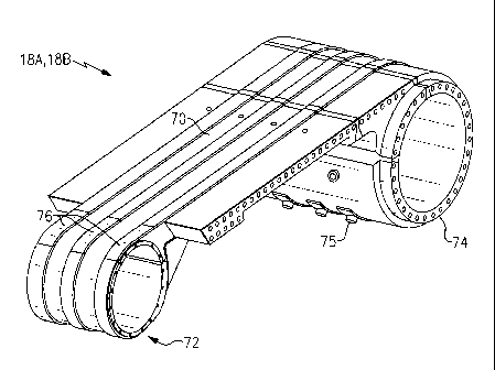
With reference to Figure 7, each load beam 18A, 18B generally includes a
generally planar surface 70 between a first cylindrical member 72 and a second
cylindrical member 74 to define passageway 14. The first cylindrical member 72
may
be relatively shorter and smaller in diameter than the second cylindrical
member 74 to
allow clearance for the associated sprocket assembly 38A, 38B. The second
cylindrical member 74 is essentially an idler over which the track assembly
28A is
guided. The load beams 18A may be integrally formed and provide mounts 75 for
sensors or other systems (Figure 9).
Adjacent to the first cylindrical member 72 at the transition to the generally
planar surface 70, each load beam 18A, 18B includes inserts 76 which
correspond to
the position of each of the plurality of track roller bearings 34 (Figure 8).
The inserts
76 resist high track roller bearing 34 contact stresses and in one non-
limiting
-5-
CA 02764258 2012-01-13
embodiment may be manufactured of a 52100 steel alloy. It should be understood
that alternative or additionally positions may include inserts 76.
With reference to Figures IOA-IOC, one non-limiting embodiment of the
insert 76-1 may be a pocket design in which the insert 76A fits within a
milled pocket
78A and retained with a multiple of fasteners 80. The inserts are essentially
extensions of rails 71 formed integral with the load beam 18A, 18B. That is,
the rails
71 extend from planar surface 70 to provide a low friction surface for roller
bearings
34. The fasteners 80 may extend for a significant length of the insert 76A. A
slot 82
may be formed within the pocket 78A to receive a key 84 which extends from the
insert 76A.
With reference to Figures 11A-11B, another non-limiting embodiment of the
insert 76-2 may be a pocket design in which the insert 76B includes a "T" slot
pocket
86 milled into the load beam 18A, 18B to receive a male shaped "T" geometry 88
formed by the insert 76B. The insert 76B may be retained with a multiple of
fasteners
90. The fasteners 90 may extend for only a relatively short length of the
insert 76B as
the "T" geometry retains the length of the insert 76B.
With reference to Figures 12A-12B, another non-limiting embodiment of the
insert 76C may also be a pocket design in which the insert 76C includes a slot
92 and
the "T" geometry extends from a surface of the load beam 18A, 18B in a manner
generally opposite that of Figures 11 A-11 B.
It should be understood that various alternative or additional insert 76
retention features may be provided. The inserts 76 provide the ability to
carry high
rolling loads without damage to the load beam material substrate, allow
replacement
of potential wear items without replacing major components.; permit a specific
match
between the rolling elements without having to address a monolithic item;
minimize
the remote likelihood of failure; and provides for flexibility to the size and
location of
load bearing components.
It should be understood that relative positional terms such as "forward,"
"aft,"
"upper," "lower," "above," "below," and the like are with reference to the
normal
operational attitude of the machine and should not be considered otherwise
limiting.
It should be understood that like reference numerals identify corresponding or
similar elements throughout the several drawings. It should also be understood
that
-6-
CA 02764258 2012-01-13
although a particular component arrangement is disclosed in the illustrated
embodiment, other arrangements will benefit herefrom.
Although particular step sequences are shown, described, and claimed, it
should be understood that steps may be performed in any order, separated or
combined unless otherwise indicated and will still benefit from the present
disclosure.
The foregoing description is exemplary rather than defined by the limitations
within. Various non-limiting embodiments are disclosed herein, however, one of
ordinary skill in the art would recognize that various modifications and
variations in
light of the above teachings will fall within the scope of the appended
claims. It is
therefore to be understood that within the scope of the appended claims, the
disclosure
may be practiced other than as specifically described. For that reason the
appended
claims should be studied to determine true scope and content.
-7-