Sélection de la langue

Search

Sommaire du brevet 2764310 

Énoncé de désistement de responsabilité concernant l'information provenant de tiers

Une partie des informations de ce site Web a été fournie par des sources externes. Le gouvernement du Canada n'assume aucune responsabilité concernant la précision, l'actualité ou la fiabilité des informations fournies par les sources externes. Les utilisateurs qui désirent employer cette information devraient consulter directement la source des informations. Le contenu fourni par les sources externes n'est pas assujetti aux exigences sur les langues officielles, la protection des renseignements personnels et l'accessibilité.

Disponibilité de l'Abrégé et des Revendications

L'apparition de différences dans le texte et l'image des Revendications et de l'Abrégé dépend du moment auquel le document est publié. Les textes des Revendications et de l'Abrégé sont affichés :

  • lorsque la demande peut être examinée par le public;
  • lorsque le brevet est émis (délivrance).
(12) Brevet: (11) CA 2764310
(54) Titre français: SOUPAPE A LANGUETTE DE CONDUITE D'ECOULEMENT
(54) Titre anglais: FLOWLINE FLAPPER VALVE
Statut: Accordé et délivré
Données bibliographiques
(51) Classification internationale des brevets (CIB):
  • F16K 15/03 (2006.01)
  • F16K 01/18 (2006.01)
  • F16K 01/42 (2006.01)
(72) Inventeurs :
  • WITKOWSKI, BRIAN C. (Etats-Unis d'Amérique)
  • SAID, NUDER M. (Etats-Unis d'Amérique)
(73) Titulaires :
  • SPM OIL & GAS INC.
(71) Demandeurs :
  • SPM OIL & GAS INC. (Etats-Unis d'Amérique)
(74) Agent: SMART & BIGGAR LP
(74) Co-agent:
(45) Délivré: 2015-06-23
(86) Date de dépôt PCT: 2010-04-20
(87) Mise à la disponibilité du public: 2010-10-28
Requête d'examen: 2013-04-26
Licence disponible: S.O.
Cédé au domaine public: S.O.
(25) Langue des documents déposés: Anglais

Traité de coopération en matière de brevets (PCT): Oui
(86) Numéro de la demande PCT: PCT/US2010/031738
(87) Numéro de publication internationale PCT: US2010031738
(85) Entrée nationale: 2011-10-20

(30) Données de priorité de la demande:
Numéro de la demande Pays / territoire Date
61/170,917 (Etats-Unis d'Amérique) 2009-04-20

Abrégés

Abrégé français

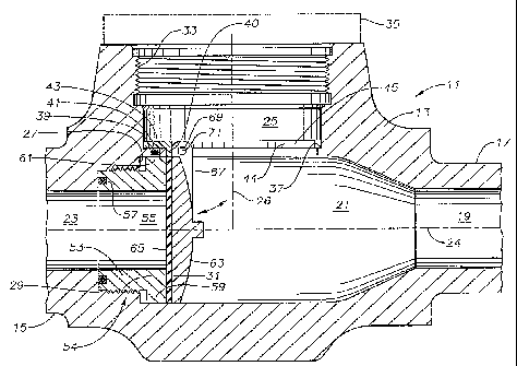
La présente invention concerne un ensemble clapet de non-retour doté d'un corps ayant une cavité centrale croisée par des passages amont et aval. Un siège est fixé par un engrènement fileté dans le passage d'écoulement amont. Un orifice d'accès croise la cavité et est doté d'un épaulement de support formé en son sein. Un dispositif de support est porté sur l'épaulement de support. Une languette est fixée pivotante au dispositif de support et située dans la cavité afin de pouvoir passer d'une position ouverte à une position fermée bloquant l'écoulement via le siège. Une partie de bord droit dans l'orifice d'accès entre en prise avec une partie de bord droit du support pour empêcher la rotation du support. Un dispositif de fixation s'étend au travers d'un trou dans l'épaulement de support en engrènement avec le siège, pour empêcher la rotation du siège.


Abrégé anglais


A check valve assembly has a body having a central cavity intersected by
upstream and downstream flow passages.
A seat is secured by a threaded engagement in the upstream flow passage. An
access bore intersects the cavity and has a support
shoulder formed in it. A holder is supported on the support shoulder. A
flapper is pivotally secured to the holder and located in
the cavity for movement between an open position and a closed position
blocking flow through the seat. A straight edge portion in
the access bore engages a straight edge portion of the holder to prevent
rotation of the holder. A fastener extends through a hole in
the support shoulder into engagement with the seat to prevent rotation of the
seat.

Revendications

Note : Les revendications sont présentées dans la langue officielle dans laquelle elles ont été soumises.


The invention claimed is:
1. A check valve assembly, comprising:
a body having a central cavity intersected by upstream and downstream flow
passages, the flow passages having a common flow passage axis, the upstream
passage
having a counterbore that defines a downstream facing shoulder;
a seat having a central orifice therethrough and secured by a threaded
engagement
into the upstream flow passage, a downstream side of the seat having a larger
diameter
than an upstream side of the seat, defining a flange having an upstream facing
shoulder
that is spaced apart from an upstream wall of the cavity by a gap and an
upstream end of
the seat abutting the downstream facing shoulder of the body, the upstream
side of the
seat having a seal that abuts and seals against the downstream facing shoulder
of the
body;
an access bore intersecting the cavity, the access bore having an access bore
axis
that is transverse to the flow passage axis;
a support shoulder formed in the access bore;
a holder insertable into the access bore, the holder extending at least
partially
aronnd the access bore and landed on the support shoulder; and
a flapper pivotally secured to the holder and located in the cavity for
movement
between an open position and a closed position blocking flow through the
orifice of the
seat.
2. The check valve assembly according to claim 1, further comprising an
anti-
rotation device having one portion on the holder and one portion on the
support shoulder,
the anti-rotation device preventing rotation of the holder.
3. The check valve assembly according to claim 1, further comprising:
a straight edge extending toward the cavity from the support shoulder; and
a lip extending from the holder, the lip having a straight portion that
registers with
7

the straight edge.
4. The check valve assembly according to claim 1, wherein:
the support shoulder extends continuously around an inner diameter of the
access
bore;
the support shoulder has a greater width portion in one area than remaining
portions of the support shoulder;
a hole is fonned in the greater width portion; and
a fastener extends through the hole and into engagement with the seat, the
fastener
preventing the seat from rotating within the upstream passage.
5. The check valve assembly according to claim 1, wherein the holder
comprises:
a disk having a central opening therethrough; and
wherein the flapper is pivotally secured to the disk by a pin and clevis
arrangement.
6. The check valve assembly according to claim 1, wherein:
the upstream flow passage has a set of internal threads; and
the seat has a set of external threads that secure to the internal threads.
7. The check valve assembly according to claim 1, wherein:
an outer diameter of the seal is less than an outer diameter of the seat and
an inner
diameter of the seal is greater than an inner diameter of the seat.
8. The check valve assembly according to claim 1, further comprising:
a set of threads formed in the access bore outward from the support shoulder;
a cap that secures to the threads in the access bore and contacts the holder
to
retain the holder on the support shoulder.
8

9. A check valve assembly, comprising:
a body having a central cavity intersected by upstream and downstream flow
passages, the flow passages having a common flow passage axis;
the upstream flow passage having a set of internal threads adjacent the cavity
and
a downstream facing shoulder upstream from the internal threads;
a seat having upstream and downstream sides, a central orifice therethrough, a
circumference having a set of external threads that engage the internal
threads in the
upstream flow passage, the upstream side of the seat having a seal and
abutting the
downstream facing shoulder and the downstream side of the seat having a larger
diameter than an upstream side of the seat, defining a flange having an
upstream facing
shoulder that is spaced apart from an upstream wall of the cavity by a gap;
an access bore intersecting the cavity, the access bore having an access bore
axis
that is perpendicular to the flow passage axis;
a support shoulder formed in the access bore and facing upward, the support
shoulder extending at least partly around an inner diameter of the access bore
adjacent a
junction of the access bore with the cavity;
a holder insertable into the access bore, the holder being a disk with a
central
opening in communication with the cavity, the holder extending at least
partially around
the access bore and being supported on the support shoulder;
a hinge block on the holder;
an anti-rotation device in the access bore and on the holder that prevents
rotation
of the holder; and
a flapper pivotally secured to the hinge block on the holder by a pin and
located in
the cavity for movement between an open position and a closed position
blocking flow
through the orifice of the seat.
10. The check valve assembly according to claim 9, wherein the anti-
rotation device
comprises:
a straight edge extending downward from the support shoulder; and
9

a lip extending downward from the holder, the lip having a straight portion
that
registers with the straight edge to assure orientation of the holder with the
seat.
11. The check valve assembly according to claim 9, wherein:
the support shoulder extends continuously around the inner diameter of the
access
bore in a plane perpendicular to the access bore axis;
the support shoulder has a greater width portion above the seat than remaining
portions of the support shoulder;
a hole is formed in the greater width portion; and
a fastener extends through the hole and into engagement with the seat, the
fastener
preventing the seat from rotating within the upstream passage.
12. The check valve assembly according to claim 9, wherein:
an outer diameter of the seal is less than an outer diameter of the seat and
an inner
diameter of the seal is greater than an inner diameter of the seat.
13. The check valve assembly according to claim 9, wherein the anti-
rotation device
comprises:
a straight edge extending downward from the support shoulder; and
wherein the hinge block engages the straight edge.
14. The check valve assembly according to claim 9, further comprising:
a set of threads formed in the access bore above the support shoulder; and
a cap that secures to the threads in the access bore and abuts an upper side
of the
holder to retain the holder on the support shoulder.
15. A check valve assembly, comprising:
a body having a central cavity intersected by upstream and downstream flow
passages, the flow passages having a common flow passage axis, the upstream
passage

having a counterbore that defines a downstream facing shoulder;
the upstream flow passage having a set of internal threads;
a seat having upstream and downstream sides, a central orifice therethrough,
the
upstream side a set of external threads that engage the internal threads in
the upstream
flow passage, and an external flange on the upstream side of the seat that is
spaced apart
from an upstream wall of the cavity by a gap and the upstream side of the seat
having a
seal and abutting the downstream facing shoulder of the body;
an access bore intersecting the cavity, the access bore having an access bore
axis
that is perpendicular to the flow passage axis;
a support shoulder formed around an inner diameter of the access bore, facing
upward, and located in a plane perpendicular to the access bore axis;
a fastener extending through a hole in the support shoulder into engagement
with
the flange of the seat to prevent the seat from rotation;
a holder insertable into the access bore, the holder being a disk with a
central
opening, the holder being supported on the support shoulder;
at least one hinge block on the holder;
a straight edge portion extending downward from the support shoulder and
engaged by the holder to prevent rotation of the holder; and
a flapper pivotally secured to the at least one hinge block on the holder and
a pin,
and located in the cavity for movement between an open position and a closed
position
blocking flow through the orifice of the seat.
16. The check valve assembly according to claim 15, wherein:
the at least one hinge block comprises a pair of hinge blocks spaced apart
from
each other.
17. The check valve assembly according to claim 15, wherein the holder has
a
configuration generally in the shape of a horse shoe.
11

18. The
check valve assembly according to claim 15, wherein the holder is removable
from the access bore separate from the seat.
12

Description

Note : Les descriptions sont présentées dans la langue officielle dans laquelle elles ont été soumises.


CA 02764310 2011-10-20
WO 2010/123889 PCT/US2010/031738
FLOWLINE FLAPPER VALVE
Cross-Reference to Related Application
This application claims priority to U.S. provisional application Serial No.
61/170,917,
filed April 20, 2009.
Field of the Invention:
This invention relates in general to a flowline check valves, and particularly
a flapper
valve for use in oilfield service operations.
Background of the Invention:
Check valves are commonly used in well hydraulic fracturing operations. Large
pumps are connected by flow lines to a well for pumping a liquid such as water
into the well
at high pressures to fracture the earth formation. Various check valves are
coupled into the
flow lines to prevent back flow to the pumps.
A typical check valve has a body with upstream and downstream flow passages
separated by a central cavity. A valve seat is pressed with an interference
fit into the
downstream flow passage. A flapper assembly is inserted through an access bore
in the body
for engaging the valve seat.
While this type of check valve works well, a high flow rate through the check
valve
may tend to cause the seat to dislodge from the flow passage. Other
improvements are also
desirable, such as simplifying the flapper assembly.
SUBSTITUTE SHEET (RULE 26)

CA 02764310 2011-10-20
WO 2010/123889 PCT/US2010/031738
Summary
The flapper valve assembly has a body with upstream and downstream flow
passages
separated by a cavity. An access bore extends into the cavity transverse to
the flow passages.
The valve seat is secured by a threaded arrangement in the upstream flow
passage, rather than
by press fitting. A holder for a flapper is supported on a support shoulder in
the access bore.
The flapper is pivotally mounted to the holder and extends into the cavity. An
anti-rotation
device prevents rotation of the holder in the access bore.
In the preferred embodiment, the anti-rotation device comprises a straight
edge
portion formed in the access bore below the shoulder. The holder has a
depending lip with a
straight edge portion that engages the straight edge portion in the access
bore.
The support shoulder has a wider section above the seat in the preferred
embodiment.
A fastener extends through a hole in the wider portion of the support shoulder
into
engagement with the seat to prevent rotation of the seat.
Preferably, the seat has an upstream side that abuts and is sealed to a
downstream
facing shoulder in the upstream passage in the body. The seat may have an
external flange on
its downstream side. In the preferred embodiment, the flange has an upstream
facing
shoulder that is spaced from an upstream wall of the cavity by a gap. The
fastener may be a
set screw that engages the rim of the flange.
Brief Description of the Drawings:
Figure 1 is a sectional view of a flapper valve constructed in accordance with
this
invention.
Figure 2 is a sectional view of the body of the flapper valve of Figure 1,
with the
components removed.
-2-

CA 02764310 2011-10-20
WO 2010/123889 PCT/US2010/031738
Figure 3 is a sectional view of the body of the flapper valve taken along the
line 3- -3
of Figure 2.
Figure 4 is a top view of a holder for the flapper valve of Figure 1.
Figure 5 is a sectional view of the holder of Figure 4, taken along the line 5-
-5 of
Figure 4.
Figure 6 is a bottom view of the holder of Figure 4.
Figure 7 is a side elevational view, as seen from the right side, of the
holder of Figure
4.
Figure 8 is a perspective view, partially sectioned, of the flapper valve of
Figure 1.
Detailed Description of the Invention:
Referring to Figure 2, flapper valve 11 has a body 13 with an upstream end 15
and a
downstream end 17. Body 13 is normally connected into a flowline that will
have flow in a
single direction, which is from the upstream end 15 toward the downstream end
17. In this
example, upstream end 15 has external threads for receiving a collar of a
conventional
coupling union. Downstream end 17 is in the mating configuration of the
coupling union.
However downstream and upstream ends 17, 15 could be reversed. Also, other
types of
connections rather than union type couplings could be utilized, such as
clamps.
Body 13 has an upstream passage 23, a central cavity or chamber 21, and a
downstream passage 19. Upstream passage 23 and downstream passage 19 are
coaxial along
a flow passage axis 24. An access bore 25 is formed in body 13 for access to
central chamber
21. Access bore 25 is located on an axis 26 that is preferably perpendicular
to and intersects
flow passage axis 24.
An upstream wall or shoulder 27 is located at an intersection between the
upstream
end of central chamber 21 and upstream passage 23. This shoulder, referred to
herein as
-3-

CA 02764310 2011-10-20
WO 2010/123889 PCT/US2010/031738
junction shoulder 27, is in a plane perpendicular to axis 24. Upstream passage
23 has a
counterbore that begins at junction shoulder 27 and extends upstream a
selected distance,
terminating at a counterbore shoulder 29. Counterbore shoulder 29 is also in a
plane
perpendicular to axis 24 and faces downstream. A set of threads 31 is formed
in upstream
passage 23 between junction shoulder 27 and counterbore shoulder 29.
Preferably, threads
31 begin at junction shoulder 27 and terminate before reaching counterbore
shoulder 29.
Access bore 25 also has a set of internal threads 33. Threads 33 are adapted
to receive
a cap 35, shown by dotted lines in Figure 1, which forms a seal within access
bore 25. An
access bore support shoulder 37 faces upward towards threads 33. Access bore
shoulder 37 is
annular but has a greater radial dimension or width relative to access bore
axis 26 on its
upstream side, defining a ledge 39. The radial dimension of ledge 39 is the
radial distance
along a radial line from axis 26 from the sidewall of access bore 25 to the
end 40 of ledge 39.
End 40 of ledge 39, which is also shown in Figure 3, is a straight edge
located in a plane
perpendicular to flow passage axis 24. Ledge end 40 could be other than
straight, however.
A hole 41, preferably threaded, is located within ledge 39 and extends
downward into central
chamber 21.
Referring also to Figure 4, a holder 43 is supported on access bore shoulder
37 and
ledge 39. Holder 43 is flat disk having a large central opening 44. In this
example, holder 43
has a horse shoe shape, with two downstream ends 45 that define a gap or
entrance to inner
opening 44; however ends 45 could be eliminated to make holder 43 completely
annular, if
desired. As shown in Figure 5, holder 43 has a depending lip 47 that extends
along its
periphery. Lip 47 has a portion that has approximately the same radial
dimension as access
bore shoulder 37, relative to access bore axis 26. As shown in Figure 6, lip
47 has a greater
radial dimension or thickness on its upstream side that matches the radial
dimension of ledge
39. Lip 47 has a straight edge portion 48 that matches and contacts axis bore
shoulder
-4-

CA 02764310 2011-10-20
WO 2010/123889 PCT/US2010/031738
straight edge portion 40. When in flush contact with each other straight edge
portions 40, 48
serve as an anti-rotation device to prevent rotation of holder 43.
As shown also in Figures 6 and 7, holder 43 has two spaced-apart hinge blocks
49 on
its lower side. Hinge blocks 49 are located at the upstream side of holder 43
and are spaced
apart from each other by inner opening 44. Each hinge block 49 has a hole 51
extending
through it. As shown in Figure 5, each hole 51 is preferably oblong. The
center points of
holes 51 coincide with each other.
Referring to Figure 1, a seat 53 has exterior threads 54 that engage internal
threads 31
of upstream passage 23. Rather than locating exterior threads 54 directly on
seat 53, other
threaded arrangements are feasible, such as employing a separate threaded
retainer ring. Seat
53 has an orifice or seat passage 55 that extends through it; passage 55 is
coaxial with and the
same diameter as flowline passages 23 and 19. Seat 53 has a circular seal 57
on its upstream
end that abuts and seals against counterbore shoulder 29. Alternately, a seal
around a
circumference of the upstream end of seat 55 in engagement with an unthreaded
portion of
upstream passage 23 may be feasible. Seat 55 has an external flange 59 on its
downstream
end that has a greater outer diameter than its threads 54. The outer diameter
of flange 59 is
approximately the same as the inner diameter of central chamber 21 at the
upstream end of
central chamber 21. Flange 59 has an upstream facing side that is spaced from
junction
shoulder 27 by a gap. A set screw 61 extends through hole 51 and engages the
outer diameter
of flange 59 to prevent seat 53 from loosening from threads 31.
Referring still to Figure 1, a flapper 63 may have a gasket 65 on its upstream
side for
engaging the downstream side of seat 53 to block any reverse flow from central
chamber 21
into upstream passage 23. Flapper 63 is pivotally connected to holder 43 by a
clevis 67
comprising two lugs (only one shown). Clevis 67 fits between the two hinge
blocks 49
(Figure 6). Clevis 67 has cylindrical holes 69 that align with hinge block
oblong holes 51
-5-

CA 02764310 2011-10-20
WO 2010/123889 PCT/US2010/031738
(Figure 6). A single pin 71 extends through holes 69 and 51 to pivotally
secure flapper 63 to
holder 43. Figure 8 illustrates one of the arms of clevis 67 and pin 71.
Flapper valve 11 is assembled by securing seat 53 to threads 31. Set screw 61
will be
secured against seat flange 59. Clevis 67 is pinned to holder 43, and then the
assembly of
flapper 63 and holder 43 is inserted into access bore 25. Holder 43 will self-
align itself
because its hinge blocks 49 will abut end 40 of ledge 39 as well as lip
straight edge portion
48. The engagement of the hinge blocks 49 and lip straight edge portion 48
with ledge end
40 prevents any rotation of holder 43 about axis 26 of access bore 25. Cap 35
is then secured
into access bore 25 to form a seal with access bore 25. A lower portion of cap
35 abuts an
upper side of holder 43 to retain holder 43 on access bore shoulder 37.
In operation, the normal flow will be from the left side of Figure 1 toward
the right.
The flow from upstream passage 23 to the right causes flapper 63 to swing open
as indicated
by the arrow. When the flow pressure ceases, gravity will cause flapper 63 to
move back to
the position shown in Figure 1. If by accident, the fluid pressure becomes
higher in
downstream passage 19 than in upstream passage 23, the engagement of flapper
63 with seat
53 will prevent any flow in the reverse direction. The threaded engagement of
seat 53 in
upstream flow passage 23 reduces the chance for downstream flow to dislodge
seat 53 from
upstream flow passage 23.
While the invention has been shown in only one of its forms, it should be
apparent to
those skilled in the art that it is not so limited but is susceptible to
various changes without
departing from the scope of the invention.
-6-

Dessin représentatif
Une figure unique qui représente un dessin illustrant l'invention.
États administratifs

2024-08-01 : Dans le cadre de la transition vers les Brevets de nouvelle génération (BNG), la base de données sur les brevets canadiens (BDBC) contient désormais un Historique d'événement plus détaillé, qui reproduit le Journal des événements de notre nouvelle solution interne.

Veuillez noter que les événements débutant par « Inactive : » se réfèrent à des événements qui ne sont plus utilisés dans notre nouvelle solution interne.

Pour une meilleure compréhension de l'état de la demande ou brevet qui figure sur cette page, la rubrique Mise en garde , et les descriptions de Brevet , Historique d'événement , Taxes périodiques et Historique des paiements devraient être consultées.

Historique d'événement

Description Date
Inactive : Correspondance - TME 2022-01-06
Lettre envoyée 2021-12-14
Exigences relatives à la révocation de la nomination d'un agent - jugée conforme 2021-11-19
Exigences relatives à la nomination d'un agent - jugée conforme 2021-11-19
Inactive : Transferts multiples 2021-11-19
Inactive : COVID 19 - Délai prolongé 2020-03-29
Représentant commun nommé 2019-10-30
Requête pour le changement d'adresse ou de mode de correspondance reçue 2018-05-31
Exigences relatives à la révocation de la nomination d'un agent - jugée conforme 2018-02-16
Exigences relatives à la nomination d'un agent - jugée conforme 2018-02-16
Demande visant la nomination d'un agent 2018-02-01
Demande visant la révocation de la nomination d'un agent 2018-02-01
Requête pour le changement d'adresse ou de mode de correspondance reçue 2018-01-10
Accordé par délivrance 2015-06-23
Inactive : Page couverture publiée 2015-06-22
Préoctroi 2015-04-07
Inactive : Taxe finale reçue 2015-04-07
Un avis d'acceptation est envoyé 2014-12-17
Lettre envoyée 2014-12-17
Inactive : Approuvée aux fins d'acceptation (AFA) 2014-11-18
Inactive : QS réussi 2014-11-18
Modification reçue - modification volontaire 2014-10-28
Inactive : Dem. de l'examinateur par.30(2) Règles 2014-04-28
Inactive : Rapport - Aucun CQ 2014-04-08
Lettre envoyée 2013-05-03
Toutes les exigences pour l'examen - jugée conforme 2013-04-26
Exigences pour une requête d'examen - jugée conforme 2013-04-26
Requête d'examen reçue 2013-04-26
Lettre envoyée 2012-02-06
Inactive : Page couverture publiée 2012-02-06
Inactive : CIB en 1re position 2012-01-30
Inactive : Notice - Entrée phase nat. - Pas de RE 2012-01-30
Inactive : CIB attribuée 2012-01-30
Demande reçue - PCT 2012-01-30
Inactive : Transfert individuel 2012-01-17
Exigences pour l'entrée dans la phase nationale - jugée conforme 2011-10-20
Demande publiée (accessible au public) 2010-10-28

Historique d'abandonnement

Il n'y a pas d'historique d'abandonnement

Taxes périodiques

Le dernier paiement a été reçu le 2015-04-09

Avis : Si le paiement en totalité n'a pas été reçu au plus tard à la date indiquée, une taxe supplémentaire peut être imposée, soit une des taxes suivantes :

  • taxe de rétablissement ;
  • taxe pour paiement en souffrance ; ou
  • taxe additionnelle pour le renversement d'une péremption réputée.

Les taxes sur les brevets sont ajustées au 1er janvier de chaque année. Les montants ci-dessus sont les montants actuels s'ils sont reçus au plus tard le 31 décembre de l'année en cours.
Veuillez vous référer à la page web des taxes sur les brevets de l'OPIC pour voir tous les montants actuels des taxes.

Titulaires au dossier

Les titulaires actuels et antérieures au dossier sont affichés en ordre alphabétique.

Titulaires actuels au dossier
SPM OIL & GAS INC.
Titulaires antérieures au dossier
BRIAN C. WITKOWSKI
NUDER M. SAID
Les propriétaires antérieurs qui ne figurent pas dans la liste des « Propriétaires au dossier » apparaîtront dans d'autres documents au dossier.
Documents

Pour visionner les fichiers sélectionnés, entrer le code reCAPTCHA :


Pour visualiser une image, cliquer sur un lien dans la colonne description du document (Temporairement non-disponible). Pour télécharger l'image (les images), cliquer l'une ou plusieurs cases à cocher dans la première colonne et ensuite cliquer sur le bouton "Télécharger sélection en format PDF (archive Zip)" ou le bouton "Télécharger sélection (en un fichier PDF fusionné)".

Liste des documents de brevet publiés et non publiés sur la BDBC .

Si vous avez des difficultés à accéder au contenu, veuillez communiquer avec le Centre de services à la clientèle au 1-866-997-1936, ou envoyer un courriel au Centre de service à la clientèle de l'OPIC.

({010=Tous les documents, 020=Au moment du dépôt, 030=Au moment de la mise à la disponibilité du public, 040=À la délivrance, 050=Examen, 060=Correspondance reçue, 070=Divers, 080=Correspondance envoyée, 090=Paiement})


Description du
Document 
Date
(aaaa-mm-jj) 
Nombre de pages   Taille de l'image (Ko) 
Dessins 2011-10-19 4 154
Abrégé 2011-10-19 1 79
Description 2011-10-19 6 310
Revendications 2011-10-19 6 240
Dessin représentatif 2012-01-30 1 26
Revendications 2014-10-27 6 201
Dessin représentatif 2015-06-03 1 28
Paiement de taxe périodique 2024-03-19 50 2 071
Rappel de taxe de maintien due 2012-01-29 1 113
Avis d'entree dans la phase nationale 2012-01-29 1 206
Courtoisie - Certificat d'enregistrement (document(s) connexe(s)) 2012-02-05 1 127
Accusé de réception de la requête d'examen 2013-05-02 1 190
Avis du commissaire - Demande jugée acceptable 2014-12-16 1 162
PCT 2011-12-08 1 20
PCT 2011-10-19 7 289
Taxes 2014-04-13 1 24
Correspondance 2015-04-06 2 49