Note : Les descriptions sont présentées dans la langue officielle dans laquelle elles ont été soumises.
CA 02764489 2017-02-01
'
DIGITAL TIRE PRESSURE GAUGE WITH BLEED VALVE
FIELD OF INVENTION
[0002] The present invention relates to pressure measurement and pressure
gauges, and more particularly to digital tire pressure gauges.
BACKGROUND
[0003] Pressure gauges are conventionally used for measuring the pressure of
a gas or a liquid, such as an air pressure. Tire pressure gauges, as an
example,
measure the inflation pressures of vehicle tires, such information being
useful for
maintaining optimal tire performance and avoiding unnecessary wear. In some
cases, a tire pressure gauge is temporarily coupled to a valve stem of a tire
to
measure the air pressure within the tire. In other cases, tire pressure gauges
are
mounted to the valve stem.
SUMMARY OF THE INVENTION
[0004] According to an embodiment of the invention, a digital tire pressure
gauge includes a housing having a first and a second end. A port is positioned
at
the first end of the housing and is adapted to engage with and open a needle
valve of a tire valve stem. A pressure sensor is disposed in the housing. The
tire
pressure gauge also
1
CA 02764489 2011-12-02
WO 2010/141881 PCT/US2010/037493
includes a processor in electronic communication with the pressure sensor. A
bleed
valve is disposed in the housing. A bleed lever is in contact engagement with
the bleed
valve. When the port is coupled to the tire valve stem, in a first operational
mode, the
bleed valve is closed and an air pressure measurement is obtained. In a second
operational mode, the bleed lever, when pressed, causes the bleed valve to
open and
to allow air to be bled out from the tire via the pressure gauge.
[0005] Another aspect of the invention includes a method for bleeding
excess air
from a tire. The method includes a step of engaging a port of tire pressure
gauge to a
valve stem of the tire. The tire pressure gauge includes a bleed valve in a
switchable
fluidic communication with the air in the tire and a bleed lever in contact
with the bleed
valve. The bleed lever is adapted to switch on and off the fluidic
communication of the
bleed valve with the air in the tire. The method then includes a step of
pressing the
bleed lever to cause at least some air to bleed out from the tire via the
bleed valve in the
pressure gauge.
BRIEF DESCRIPTION OF THE DRAWINGS
[0006] Understanding of the present invention will be facilitated by
consideration of
the following detailed description of the exemplary embodiments of the present
invention taken in conjunction with the accompanying drawings, in which like
numerals
refer to like parts and in which:
[0007] FIG. 1 is a perspective view of a digital tire pressure gauge,
according to an
embodiment of the invention;
2
CA 02764489 2011-12-02
WO 2010/141881 PCT/US2010/037493
[0008]
FIG. 2 is a top view of the gauge of FIG. 1, according to an embodiment of
the invention;
[0009]
FIG. 3 is a bottom view of the gauge of FIG. 1, according to an embodiment
of the invention;
[0010]
FIG. 4 is a side view of the gauge of FIG. 1, according to an embodiment of
the invention;
[0011]
FIG. 5 is a schematic diagram of components of the gauge of FIG. 1,
according to an embodiment of the invention;
[0012]
FIG. 6 is a perspective cross-sectional view of the gauge of FIG. 1, according
to an embodiment of the invention;
[0013]
FIG. 7A is a cross-sectional view of the gauge of FIG. 1, wherein the gauge is
in a pressure measurement mode with a bleed valve mechanism in a closed state,
according to an embodiment of the invention;
[0014]
FIG. 7B is a cross-sectional view of the of FIG. 1, wherein the gauge is in a
bleeding mode with the bleed valve mechanism in an open state, bleeding air
out of the
gauge and the tire, according to an embodiment of the invention;
[0015]
FIG. 8 is a process flow of using the gauge of FIG. 1 to check air pressure
and bleed excess air from a tire, if overinflated, according to an aspect of
the invention;
and
3
CA 02764489 2015-11-06
[0016] FIGs. 9A and 9B are a process flow diagram of certain steps of
preparing
the gauge of FIG. 1 for use.
DETAILED DESCRIPTION
[0017] It is to be understood that the figures and descriptions of the
present
invention have been simplified to illustrate elements that are relevant for a
clear
understanding of the present invention, while eliminating, for purposes of
clarity,
many other elements found in typical tire pressure gauges and digital tire
pressure
gauges. However, because such elements are well known in the art, and because
they do not facilitate a better understanding of the present invention, a
discussion of
such elements is not provided herein. The disclosure herein is directed to all
such
variations and modifications known to those skilled in the art.
[0018] Further, it should be understood that the several views of the
housings,
displays and general configurations shown in the figures include many
decorative or
ornamental features, aspects of which the particulars may be changed while
maintaining the device's utility. The scope of the claims should not be
limited by the
preferred embodiments and examples that follow, but should be given the
broadest
interpretation consistent with the description as a whole.
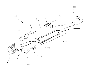
[0019] Referring to FIGS. 1 - 4, a digital tire pressure gauge 100 is
illustrated
according to an embodiment of the invention. Gauge 100 has a generally
encompassing housing or wall 110. In an exemplary embodiment, housing 110
includes a top cover 115 and a bottom wall 120. In other embodiments, housing
110
may have more than or less than two covers. Gauge 100 includes a port 30
adapted
to
4
CA 02764489 2011-12-02
WO 2010/141881 PCT/US2010/037493
engage with and open the needle valve on a suitable tire valve stem. A tire
valve stem
is typically in the form of a tube, threaded on the exterior near the end
thereof, to permit
attachment of a protective cap, and having a valve, referred to variously as a
pin valve,
bleeder valve, or Schrader valve. This type of valve is kept normally closed
by a
combination of air pressure and a spring urging a stopper into contact with an
opening.
A pin extending out of the valve may be urged inward, such as by a piston in a
nozzle of
a service station air hose, to open the valve to permit the introduction of
pressurized air
into the tire. Port 30 may include such a pin.
[0020] A light source 140 is provided near port 30, and may be employed for
illumination. In an exemplary embodiment, light source 140 is a light emitting
diode
(LED). Light source 140 is operable via a switch 170. In an exemplary
embodiment,
switch 170 is in form of a push button. An advantage of light source 140 is
that a user
may use its illumination to locate a tire valve stem in unlit or poorly lit
areas and avoid
having to grope the tire valve stem.
[0021] A grip area 135 is provided on top cover 115 at an end proximal to
port 130.
In an exemplary embodiment, grip area 135 includes ridges and has a curvature
complementing the contours of a human thumb. Top cover 115 further includes a
display 150 and a set 155 of buttons. Display 150 includes an alphanumeric
display,
which may be, for example, a liquid crystal display. Housing 110 further
includes a
through-aperture 160 at an end proximal to display 150. In an exemplary
embodiment,
aperture 160 is adapted to receive a lanyard for ease of handling and storage
of gauge
100. A bleed lever 145 pivots about points 165 on bottom cover 120 at an end
proximal
CA 02764489 2011-12-02
WO 2010/141881 PCT/US2010/037493
to port 30.
[0022]
Gauge 100 includes a pressure sensor (not shown) located within housing
110. Referring now also to FIG. 5, there is shown a block diagrammatic view of
an
arrangement 500 suitable for use in gauge 100 of Figures 1 ¨ 4. An exemplary
arrangement 500 generally includes a processor 510, optional analog to digital
(a/d)
converter 540, pressure sensor 530, a memory 550, a display 560, an audio
device 580,
and set 570 of input buttons.
[0023]
"Processor", as used herein, generally refers to a circuit arrangement that
may be contained on one or more silicon chips, and/or integrated circuit (IC)
boards,
and that contains a Central Processing Unit (CPU). The CPU may generally
include an
arithmetic logic unit (ALU), which performs arithmetic and logical operations,
and a
control unit, which extracts instructions from memory and decodes and executes
them,
calling on the ALU when necessary.
[0024] Processor 510 may take the form of a microprocessor, and may be a low
power CMOS processor with an embedded analog to digital converter, by way of
non-
limiting example only. The present invention is operable with computer storage
products or computer readable media that contain program code for performing
the
various computer-implemented operations. The computer-readable medium is any
data
storage device that can store data which can thereafter be read by a computer
system
such as a microprocessor. The media and program code may be those specially
designed and constructed for the purposes of the present invention, or they
may be of
6
CA 02764489 2011-12-02
WO 2010/141881 PCT/US2010/037493
the kind well known to those of ordinary skill in the computer software arts.
Examples of
computer-readable media include, but are not limited to magnetic media such as
hard
disks, floppy disks, and magnetic tape; optical media such as CD-ROM disks;
magneto-
optical media; and specially configured hardware devices such as application-
specific
integrated circuits (ASICs), programmable logic devices (PLDs), and ROM and
RAM
devices. Examples of program code include both machine code, as produced, for
example, by a compiler, or files containing higher-level code that may be
executed
using an interpreter.
[0025] Processor 510 may include multiple inputs and outputs. In the
exemplary
configuration illustrated in FIG. 5, processor 510 has an input coupled to
pressure
sensor 530 optionally via analog-to-digital converter (A/D) 540. For example,
where
pressure sensor 530 provides an analog output signal indicative of a pressure
sensed
using port 30, A/D converter 540 may communicate a digital signal indicative
of the
analog signal output from pressure sensor 530 to processor 510. Where pressure
sensor 530 provides a digital signal directly, A/D converter 540 may
optionally be
omitted. Also, where processor 510 is adapted to receive analog signals output
from
pressure sensor 530 directly, A/D converter 540 may optionally be omitted. A/D
converter 540 may be selected based upon size limitations of housing 110, an
expected
output from pressure sensor 530, accepted input for processor 510 and
available power
source 520 for gauge 100, for example. Processor 510 may also be coupled to
memory
550 to allow it to access its data contents.
[0026] Pressure sensor 530 may be any one of a number of conventional
sensors for
7
CA 02764489 2011-12-02
WO 2010/141881 PCT/US2010/037493
detecting fluid pressure, and particularly air pressure, and selected to
provide
acceptable response over a range of pressures anticipated in a particular
application.
By way of example, pressure sensor 530 may incorporate a MEMS based pressure
die.
[0027] In an exemplary embodiment, set 570 of input buttons includes three
buttons:
a first button is labeled "SET," a second button is labeled "UP" and a third
button is
labeled "DOWN." In other embodiments, set 570 may include more than or less
than
three buttons with different functionalities.
[0028] Referring now to FIG. 6, there is illustrated a perspective partial
cross-
sectional view of gauge 100. A sensor housing 630 is disposed within housing
110. An
air passage 610 and an air chamber 620 are defined in sensor housing 630. Air
from a
tire flow through air passage 610 into air chamber 620. In the illustrated
embodiment, a
bleed valve 600 is disposed in sensor housing 630. Bleed valve 600 is operable
via
bleed lever 145.
[0029] Referring now to FIG. 7A, a cross-sectional view of bleed valve 600
in first
operational mode is illustrated. In an exemplary embodiment, sensor housing
630 is
made of a plastic material, for example, ABS. In the illustrated embodiment,
an insert
730 is made of brass and is co-molded with sensor housing 630. The internal
surface
of insert 730 has internal threads defined thereon. A stem tube 720 has
external
threads defined on its external surface and is threadedly engaged with insert
730. In an
exemplary embodiment, stem tube 720 is made of nickel plated brass. A stem 710
is
inserted in stem tube 720. Stem 710 is in contact engagement with bleed lever
145 at a
8
CA 02764489 2011-12-02
WO 2010/141881 PCT/US2010/037493
first end. Stem 710 has a first head 750 protruding radially distal from the
first end and
outside stem tube 720. Stem 710 has a second head 770 protruding radially
proximal
to the first end and inside stem tube 720. A spring 740 is disposed along stem
710,
between second head 770 and a step 760 in stem tube 720. In FIG. 7A, first
head 750
is illustrated as covering an opening 760 (of FIG. 7B) of stem tube 720. Bleed
valve
600 is, therefore, in a switchable fluid communication with air in the tire.
[0030] Referring now to Fig. 7B, a cross-sectional view of bleed valve 600
is second
operational mode is illustrated. In the second operational mode, when bleed
lever 145
is pressed towards gauge 100, lever 145 pivots about point 165 and urges stem
710
further into stem tube 720. Head 750, therefore, is caused to move away from
opening
760, thereby creating a pathway for air in air passage 610 and in air chamber
620 to
bleed through stem tube 720. Spring 740, which is compressed between second
head
770 and step 760 urges stem 710 towards bleed lever 145, when the pressing
force on
lever 145 is removed. Head 750, thus, closes opening 760, thereby closing the
air
pathway. Bleed lever 145 is, therefore, adapted to switch on and off the
fluidic
communication of bleed valve 600 with the air in the tire.
[0031] Referring now to FIG. 8, a process flow is illustrated for checking
air pressure
of a tire and for bleeding excess air from the tire, if overinflated. At block
810, pressure
gauge 100 is engaged with a valve stem of a tire. The air pressure of the tire
is
checked in display 150. The user checks whether the measured air pressure is
above a
threshold, at block 830. If the measured air pressure is not above the
threshold, the
user disengages the pressure gauge from the valve stem, at block 850. lf,
however, the
9
CA 02764489 2011-12-02
WO 2010/141881 PCT/US2010/037493
measured air pressure is above the threshold, while keeping the pressure gauge
engaged with the valve stem, the user presses bleed lever 145 to cause excess
air from
the tire to bleed out through the pressure gauge, at block 840. The steps in
blocks 820,
830, 840 are repeated until the measured air pressure is no longer above the
threshold.
In an exemplary embodiment, audio device 580 (of FIG. 5) emits a first sound
to
indicate that gauge 100 has obtained an air pressure reading, which reading is
displayed on display 560 (of FIG. 5). In an exemplary embodiment, audio device
580
(of FIG. 5) is adapted to emit a series of sounds to indicate whether the
measured air
pressure is above or below the threshold pressure.
[0032] An advantage of the described embodiment of the invention is that
bleed
valve 600 facilitates bleeding of air from a vehicle tire without having to
remove
pressure gauge 100 from a tire valve stem. When a user inflates a tire, it is
possible
that the user may have inadvertently over-inflated the tire. Conventionally,
then the
user measures a tire air pressure by engaging a tire pressure gauge to a valve
stem. If
the measured air pressure is in excess of a desired pressure level, the user
has to
remove the pressure gauge and manually bleed excess air from the tire. Then
the user
has to again engage the pressure gauge to check the tire air pressure. These
steps
have to be repeated until a desired tire pressure threshold is reached. An
advantage of
the tire pressure with a bleed valve is that the user does not have to remove
the
pressure gauge from the valve stem; rather, while keeping the pressure gauge
engaged
with the valve stem, the user simply presses on bleed lever and bleeds excess
air from
the tire. The user may intermittently stop bleeding excess air by releasing
the bleed
CA 02764489 2011-12-02
WO 2010/141881 PCT/US2010/037493
lever and check the air pressure in the display and repeat the steps until the
tire is no
longer overinflated.
[0033] Referring now to FIG. 9A and 9B, there is shown a block diagrammatic
representation of a process 900 according to an aspect of the present
invention, and
being suitable for use with gauge 100 (of FIG. 1). In an initial step,
indicated by block
905, upon initially powering up of gauge 100 (of FIG. 1), the gauge enters a
default
initial display mode. In the default mode, processor 510 (of FIG. 5) accesses,
such as
from memory 550 (of FIG. 5), a stored default target pressure, and a stored
default unit,
and causes that target and unit to be displayed, as indicated by block 910.
[0034] In response to a SET signal, as indicated by block 912, gauge 100
enters a
display unit select mode, as indicated by block 915. In the display unit
select mode, a
unit will blink to prompt the user to select a unit. For example, initially,
PSI may blink.
In response to the user pressing the up and down keys, the unit that is
blinking will
change. In response to a further SET signal, the unit for display will be
selected and
stored in memory, as indicated by block 917 and 920, and the device will enter
a goal
setting mode, as indicated by block 925.
[0035] In the goal setting mode, the user is prompted to enter a first
target tire
pressure, as indicated by block 930. The first tire pressure may be for the
front tires, for
example. The prompting may take the form of causing the emitters corresponding
to a
set of wheels, such as the front wheels or the rear wheels, to blink. A
default target tire
pressure is displayed, and may be incremented up and down in response to
pressing of
11
CA 02764489 2015-11-06
the up and down buttons by the user. When a desired first target tire pressure
is
displayed, the user may press the SET button. This will generate a SET signal,
indicated by block 935, to the processor 510 (of FiG. 5), which will then
store, as
indicated by block 940, the then-displayed value as the first target tire
pressure in
memory 550 (of FIG. 5). Referring now to Fig. 9B, the processor may then
prompt
the user to enter a second target tire pressure, as indicated by block 945.
The
second target tire pressure may be for the rear tires. The prompting may take
the
form of causing the emitters corresponding to the rear wheels to blink. A
default
second target tire pressure may be displayed. The displayed second target tire
pressure may be incremented up and down in response to pressing of the up and
down buttons by the user. When a desired second target tire pressure is
displayed,
the user may press the SET button, as indicated by block 947. In response, the
processor will store the then-displayed second target tire pressure in memory,
as
indicated by block 950. The device will then enter the remote display
operating
mode.
[0036] Thus, a
number of preferred embodiments have been fully described
above with reference to the drawing figures. The scope of the claims should
not be
limited by the preferred embodiments and examples, but should be given the
broadest interpretation consistent with the description as a whole.
12