Note : Les descriptions sont présentées dans la langue officielle dans laquelle elles ont été soumises.
CA 02765065 2011-12-09
WO 2010/145040 PCT/CA2010/000969
District Energy Sharing System
Field of Invention
This invention relates to a district energy sharing system for sharing thermal
energy between a server and a client in a district.
Background
Traditional building heating and cooling systems use primary high grade energy
sources such as electricity or fossil fuels to provide space heating and/or
cooling,
and to heat or cool water used in the building. The process of heating or
cooling
the building spaces and water converts this high grade energy into low grade
waste heat with high entropy which leaves then the building and is returned to
the environment. For example, heated water from showers or sinks will be
discharged into the sewer, and thermal energy in heated air will radiate and
conduct through exterior walls and into atmosphere.
Building heating and cooling systems consume major quantities of non-
renewable resources and contribute substantially to global warming. Also, many
industry processes discharge large quantities of low grade thermal energy that
causes further warming of water courses and atmosphere.
Attempts have been made to utilize natural heat source and heat sinks to
provide
efficient, environmentally friendlier approaches to heating and cooling a
building;
for example, and as shown in Figure 1 (PRIOR ART), buildings in a district can
each be served individually by independent ground source heat pump systems.
This approach unfortunately, requires significant infrastructure costs as each
homeowner would need to install a heat pump system with a geothermal ground
loop.
A typical building district is shown schematically in Figure 2 (PRIOR ART) and
comprising client buildings each fluidly coupled to a single-pipe warm water
distribution circuit. In this schematic, a heat source (e.g. a mechanical
plant
1
CA 02765065 2011-12-09
WO 2010/145040 PCT/CA2010/000969
having a geothermal ground loop) is thermally coupled to the circuit by a heat
exchanger; another heat exchanger is provided to thermally couple the circuit
to
another fluid flow distribution circuit in an adjacent district. Each building
can be
provided with a heat pump which is thermally coupled to the circuit and which
converts thermal energy from the circuit into useful heat for domestic space
or
water heating. One particular disadvantage with such a district is that each
building is serially connected to the circuit and thus the overall efficiency
of
building heat pump operation is compromised as downstream heat pumps will be
working harder when all upstream heat pumps are drawing heat from the circuit.
Efficient operation is also compromised when some building heat pumps are
heating and some are cooling, as there will be large temperature variances
along
the circuit and additional measures will need to be employed to maintain the
temperature of the circuit within its design operating range.
It would therefore be useful to provide an improved and cost-effective system
to
heat and/or cool buildings which re-uses at least some low grade waste heat
produced as a result of domestic space and water heating and cooling
processes.
Summary
According to one aspect of the invention, there is provided district energy
sharing system comprising a thermal energy circuit and a heat pump assembly.
The thermal energy circuit comprises: a warm liquid conduit for flow of a heat
transfer liquid therethough at a first temperature; and a cool liquid conduit
for flow
of the heat transfer liquid therethrough at a second temperature that is lower
than
the first temperature. The heat pump assembly comprises: a reversible heat
pump; a building heat exchanger thermally coupled to the heat pump and for
thermally coupling to a client building; a circuit heat exchanger thermally
coupling
the heat pump to the thermal energy circuit; piping fluidly coupling the
circuit heat
exchanger to the warm and cool liquid conduits; at least one circulation pump
coupled to the piping; and a valve assembly comprising at least one control
valve
2
CA 02765065 2011-12-09
WO 2010/145040 PCT/CA2010/000969
coupled to the piping and switchable between a heating mode wherein a fluid
pathway is defined through the piping for flow of the heat transfer liquid
from the
warm liquid conduit through the circuit heat exchanger and to the cool liquid
conduit, and a cooling mode wherein a fluid pathway is defined through the
piping for flow of the heat transfer fluid from the cool liquid conduit
through the
heat exchanger and to the warm liquid conduit. The valve assembly can be
further switchable into an off mode wherein the warm and cool liquid conduits
are
not in fluid communication with the heat exchanger through the piping.
The valve assembly can comprise a pair of three-way control valves wherein a
first three-way control valve is fluidly coupled to the warm liquid conduit,
cool
liquid conduit, and an inlet of the circuit heat exchanger, and a second three-
way
control valve is fluidly coupled to the warm liquid conduit, cool liquid
conduit, and
an outlet of the circuit heat exchanger. When the valve assembly is in the
heating
mode the first three-way control valve is closed to the cool liquid conduit
and
open to the warm liquid conduit and the inlet of the circuit heat exchanger,
and
the second three-way control valve is closed to the warm liquid conduit and
open
to the cool water conduit and the outlet of the circuit heat exchanger.
Alternatively, the valve assembly can comprise a single four-way control valve
having four ports and a rotary actuator. The four ports comprise a first port
fluidly
coupled to the warm liquid conduit, a second port fluidly coupled to an inlet
of the
circuit heat exchanger, a third port fluidly coupled to the cool liquid
conduit, and a
fourth port fluidly coupled to an outlet of the circuit heat exchanger. The
rotary
actuator fluidly couples the first and second ports and fluidly couples the
third
and fourth ports in the heating mode, and fluidly couples the first and fourth
ports
and fluidly couples the second and third ports in the cooling mode.
According to another aspect of the invention, a district energy sharing system
comprising the thermal energy circuit and a grey water injection assembly. The
grey water injection assembly comprises: a grey water supply conduit fluidly
coupled to the warm or cool water conduit and for fluidly coupling to a grey
water
3
CA 02765065 2011-12-09
WO 2010/145040 PCT/CA2010/000969
source such that grey water is supplied to the warm or cool water conduit; a
pressure control device fluidly coupled to the grey water supply conduit or
thermal energy circuit and operable to regulate water pressure within the
thermal
energy circuit; a client building heat transfer apparatus fluidly coupled to
the
warm and cool water conduits and for thermally coupling to a client building
such
that thermal energy can be transferred between the thermal energy circuit and
the client building; and a grey water take-off conduit fluidly coupled to the
warm
water conduit and for fluidly coupling to a client building such that grey
water can
be supplied to the building for non-potable uses.
The grey water injection assembly can further comprise a filtration device
fluidly
coupled to the grey water supply conduit upstream of the pressure control
device. The pressure control device can comprise at least one pump operable to
increase the pressure of the grey water above the pressure of water in the
thermal energy circuit. The pressure control device can further comprise at
least
one control valve and a cushion tank fluidly coupled to the pump and operable
to
vary the flow rate of grey water to the warm water conduit.
According to yet another aspect of the invention, district energy sharing
system
comprises a first and second thermal energy circuit, and a thermal energy
transfer station for thermally coupling the first and second thermal energy
circuits. The first and a second thermal energy circuit each comprisie: a warm
liquid conduit for flow of a heat transfer liquid therethough at a first
temperature;
a cool liquid conduit for flow of the heat transfer liquid therethrough at a
second
temperature that is lower than the first temperature; and a circuit pump
coupled
to at least one of the warm and cool liquid conduits for pumping the heat
transfer
liquid therethrough. The thermal energy transfer station comprises at least
one of
a: liquid transfer assembly fluidly coupling the first and second thermal
energy
circuits and comprising a pump operable to flow heat transfer fluid
therebetween;
and a heat exchanger assembly thermally coupling and fluidly separating the
first and second thermal energy circuits.
4
CA 02765065 2011-12-09
WO 2010/145040 PCT/CA2010/000969
In one aspect the thermal energy transfer station comprises only the liquid
transfer assembly, which further comprises: a warm liquid transfer conduit
fluidly
coupling the warm liquid conduits of the first and second thermal energy
circuits;
a cool liquid transfer conduit fluidly coupling the cool liquid conduits of
the first
and second thermal energy circuits; and a changeover assembly comprising
piping fluidly coupled to the warm or cool liquid transfer conduits and to the
pump, and at least one control valve fluidly coupled to the piping and
operable in
a first mode which defines a fluid pathway through the piping from the first
thermal energy to the second thermal energy circuit, and a second mode which
defines a fluid pathway through the piping from the second thermal energy
circuit
to the first thermal energy circuit.
In another aspect, the thermal energy transfer station comprises only the heat
exchanger assembly, which further comprises: a liquid-to-liquid heat exchanger
having a first heat transfer zone and a second heat transfer zone thermally
coupled to but fluidly separated from the first heat transfer zone; first
liquid
transfer piping fluidly coupling the first heat transfer zone to the warm and
cool
liquid conduits of the first thermal energy circuit and second liquid transfer
piping
fluidly coupling the second heat transfer zone to the warm and cool liquid
conduits of the second energy circuit; and a pair of transfer pumps each
respectively fluidly coupled to the first and second liquid transfer piping
and
operable to flow liquid from the first thermal energy circuit through the
first heat
transfer zone, and to flow liquid from the second thermal energy circuit
through
the second heat transfer zone.
The thermal energy transfer station can further comprise a pressure control
device and fluid conduit fluidly coupled to the first and second liquid
transfer
conduits, which is operable to regulate the pressure between the first and
second
thermal energy circuits. The pressure control device in this case comprises at
least one of a pressure reducing control valve and a booster pump.
5
CA 02765065 2011-12-09
WO 2010/145040 PCT/CA2010/000969
The thermal energy transfer station can further comprise at least one server
plant. Each server plant comprises a heat pump assembly thermally coupling one
of the first or second liquid transfer conduits to at least one of a heat
source and
a heat sink.
Brief Description of Drawings
Figure 1 is a schematic of multiple buildings each individually serviced by
independent ground source heat pump systems. (PRIOR ART)
Figure 2 is a schematic of multiple buildings each fluidly coupled to a single-
pipe
warm water supply circuit. (PRIOR ART)
Figure 3 is a schematic of a district energy sharing system according to one
embodiment comprising a thermal energy circuit having a warm water conduit
and a cool water conduit, which are both thermally coupled to multiple client
buildings and to a thermal server plant in a district.
Figure 4 is a schematic of a district energy sharing system according to
another
embodiment comprising the thermal energy circuit thermally coupled to multiple
client buildings and a thermal server plant in a district, wherein heat
transfer
apparatus in each building and in the server plant are illustrated.
Figures 5(a) to (i) are schematic illustrations of a heat pump assembly in one
client building, wherein Figures 5(a) to (c) show a heat pump assembly
according
to one embodiment having a reversible heat pump and a pair of three-way
control valves configured to operate in a heating mode (Figure 5(a)), in a
cooling
mode (Figure 5(b)), and in an off mode (Figure 5(c)), and Figures (d) to (f)
show
a heat pump assembly according to another embodiment having a reversible
heat pump and a single four-way control valve configured to operate in a
heating
mode (Figure 5(d)), in a cooling mode (Figure 5(e)), and in an off mode
(Figure
5(f)), and Figures 5(g) to (i) shows a heat pump assembly according to yet
another embodiment having a reversible heat pump and four two-way control
valves.
6
CA 02765065 2011-12-09
WO 2010/145040 PCT/CA2010/000969
Figure 6 is a schematic of a district energy sharing system according to
another
embodiment comprising a thermal server plant thermally coupled to the thermal
energy circuit, and a multiple unit local heat transfer plant servicing
multiple client
buildings in the district also thermally coupled to the thermal energy
circuit.
Figure 7 is a schematic of a district energy sharing system according to
another
embodiment comprising a thermal server plant and multiple client buildings
each
having a heat transfer apparatus and being directly thermally coupled to the
warm and cool water conduits of the thermal energy circuit.
Figure 8 is a schematic of a district energy sharing system according to yet
another embodiment comprising a combined multiple unit local heat transfer
plant servicing multiple client buildings in a district and thermal server
plant.
Figures 9(a) to (h) are schematics of a district energy sharing system
according
to yet other embodiments comprising a pair of thermal energy circuits
thermally
coupled together by an thermal energy transfer station wherein Figure 9(a)
shows each thermal energy circuit thermally coupled to multiple client
buildings
and a thermal server plant, Figure 9(b) is a detail view of the transfer
station
according to one embodiment for serving circuits having the same pressure
zone, Figure 9(c) is a detail view of the transfer station according to
another
embodiment for serving circuits having different pressure zones, Figure 9(d)
is a
detail view of the transfer station according to yet another embodiment for
serving circuits having different pressure zones and having a pair of thermal
server plants, and Figures 9(e) to (h) show different modes of operation for
transfer of heat between circuits of the transfer station shown in Figure
9(b).
Figure 10 is a photograph of a district with an illustration of one embodiment
of
the district energy sharing system overlaid onto the photographed district.
Figure 11 is a schematic of a process of sharing thermal energy within one
embodiment of the district energy sharing system.
7
CA 02765065 2011-12-09
WO 2010/145040 PCT/CA2010/000969
Figure 12 is a schematic of a district energy sharing system having a grey
water
injection assembly according to yet another embodiment.
Detailed Description of Embodiments of the Invention
Referring to Figure 3 and according to one embodiment, a district energy
sharing
system (DESS) 10 comprises a thermal energy circuit 12 which circulates and
stores thermal energy in water, at least one client building 20 thermally
coupled
to the circuit 12 and which removes some thermal energy from the circuit 12
("thermal sink") and/or deposits some thermal energy into the circuit 12
("thermal
source") (note: the client buildings 20 shown in this Figure are shown only
drawing thermal energy from the circuit 12 and thus are all operating as heat
sinks), and at least one thermal server plant 21 that can be thermally coupled
to
external thermal sources and/or sinks (e.g. a geothermal ground source) and
whose function is to maintain thermal balance within the DESS 10. The DESS 10
can also include a network control and monitoring system to regulate, measure,
and optimize the transfer of thermal energy during system operation (not
shown).
The circuit 12 comprises a pair of water conduits 14, 16 respectively flowing
water at different temperatures and which serve to transfer and store thermal
energy between the sources and sinks (respectively, "warm" and "cool"
conduits).
A heat transfer apparatus 30 in each building 20 fluidly interconnects the
warm
and cool water conduits 14, 16 such that warm water can flow from the warm
water conduit 14 through the heat transfer apparatus 30 and then into the cool
water conduit 16, or vice versa. In the former configuration, the heat
transfer
apparatus 30 operates to draw heat from the warm water conduit 14 to heat the
building 20 and then deposits the cooled water into the cool water conduit 16;
in
the latter configuration, the heat transfer apparatus 30 operates to extract
heat
from the building 20 to cool the building 20 and deposits that extracted heat
into
the warm water conduit 14.
8
CA 02765065 2011-12-09
WO 2010/145040 PCT/CA2010/000969
The warm water conduit 14 and cool water conduit 16 are two separate and
parallel closed loops of piping which are fluidly interconnected only at the
client
buildings 20 and server plant 21. The piping system in this embodiment uses
plain water as a heat transfer liquid and the pipe is single wall uninsulated
High
Density Polyethylene (HDPE). However, other liquids can be used as a heat
transfer liquid according to another embodiment, since the circuit 12 is a
closed
fluid loop.
One or more circulation pumps 22 are fluidly coupled to the piping and are
operated to circulate water through the warm and cool water conduits 14, 16.
In
particular, water is pumped through the warm water conduit 14 at a first
temperature ("warm water") and cool water is pumped through the cool water
conduit 16 at a second temperature that is lower than the warm water
temperature ("cool water"). A suitable temperature range for the warm water is
between 10 and 30 C and a suitable temperature range for the cool water is
between 5 and 20 C. The two-pipe arrangement provides an assurance that all
client buildings 20 get the same temperature water for the supply to the heat
pumps.
While Figure 3 is shown to have a pair of circulation pumps 22 each fluidly
coupled to the warm and cool water conduits 14, 16, these pumps can be
replaced or supplemented by circulation pumps 24 in one or more client
buildings
20 (client pumps), or in the server plant 21 (server pumps) to circulate water
throughout the circuit 12.
In normal use any client building 20 that has a net heating load draws water
off
the warm water conduit 14 and returns it to the cool water conduit 16, and any
client building 20 in net cooling mode draws water off the cool water conduit
16
and returns it to the warm water conduit 14. Transfer of water from warm to
cool
water conduits or cool to warm water conduits increases the pressure of the
receiving conduit, driving water back to the other conduit through the thermal
9
CA 02765065 2011-12-09
WO 2010/145040 PCT/CA2010/000969
server plant 21, where heat is added or removed. This transfer is achieved by
natural means or by the use of the circulation pumps 22, 24.
The thermal energy circuit 12 is designed to ensure that the pressure
difference
between the warm and cool water conduits 14, 16 is always kept as low as
possible to ensure that the client pumps 24 do not have to overcome a large
head that could limit the flow to the client and increase the pumping
horsepower.
This is achieved by maintaining low velocities in the water conduits 14, 16
with
commensurate low friction loss and by normally maintaining the flow in the
warm
and cool conduits 14, 16 in the same direction, so that pressure drop from
friction
is similar in both conduits 14, 16 along the length of the circuit 12.
The thermal energy circuit 12 also acts as a thermal storage device through
oversizing the water conduits 14, 16 and varying the temperature in the water
conduits 14, 16 over time. A secondary level of thermal storage can be
provided
by the soil surrounding the conduit that ameliorates temperature change during
high load conditions. Oversizing the conduits 14, 16 also reduces friction
loss
and pumping horsepower.
When heat is removed from the thermal energy circuit 12 to heat one or more
client buildings 20 in the district and heat removed from one or more other
buildings 20 in the district is transferred to the thermal energy circuit 12 ,
these
client buildings 20 in effect share the thermal energy in the thermal energy
circuit
12 in their heating and cooling processes which is more energy efficient than
having the client buildings 20 discharging heat into the environment as a
result of
independently operated heating and cooling processes. While it may be possible
that the thermal energy in the thermal energy circuit 12 can be maintained
fairly
constant by designing the DESS 10 so that the client and heat source buildings
20 collectively remove and return about the same amount of thermal energy, the
thermal sever plant 21 is provided to ensure a thermal balance is maintained
in
the DESS 10. That is, a net amount of thermal energy removed from the circuit
12 by the client buildings 20 is returned to the circuit 12 by the thermal
server
CA 02765065 2011-12-09
WO 2010/145040 PCT/CA2010/000969
plant 21 by drawing thermal energy from a coupled external thermal source 23;
similarly, a net amount of energy deposited into the circuit 12 by the client
buildings 20 is removed by the server plant 21 and stored in a coupled
external
heat sink 23. The heat source or sink 23 for the server plant 21 can be a geo-
exchange field, ground water, ocean, lake, sewer, effluent, refrigeration
plants,
solar collectors, ice rinks, or industrial processes. These alternatives for
server
plant types include any source that can produce or absorb heat, and transfer
the
heat to or from the warm and cool water conduits.
Selecting suitable server heat sources will depend at least on part on the
temperature and capacity profiles as well as the form of the heat provided by
the
heat source. Some server heat sources provide consistent capacity whereas
others provide a variable capacity based on weather conditions, time of year,
time of day and other conditions. Selection of server heat sources is based on
the ability to satisfy client load profiles, and computer modelling of
capacity
profiles can be performed to design a system that can operate satisfactorily
under any anticipated load.
Selecting suitable server heat sinks will depend at least on the ability of
the heat
sink to store thermal energy for short or long terms. The ability to store
energy is
based on the mass and specific heat of the storage medium as well as the rate
of
heat loss or gain. A viable high capacity storage system can incorporate phase
change medium where the heat of fusion can be used to store large amounts of
energy in a relatively small space and without large temperature change.
Eutectics can be selected that will pass through a phase change at a specific
temperature.
Short-term storage would typically be for a few hours and could be applied to
diurnal variations. Long-term storage could be applied to seasonal variations
depending upon the ability of the medium to hold the heat. Thermal degradation
is of less concern for short term than it is for long-term storage. Even if
the
11
CA 02765065 2011-12-09
WO 2010/145040 PCT/CA2010/000969
storage degrades, it can be viable if it is being charged by energy that would
otherwise be wasted.
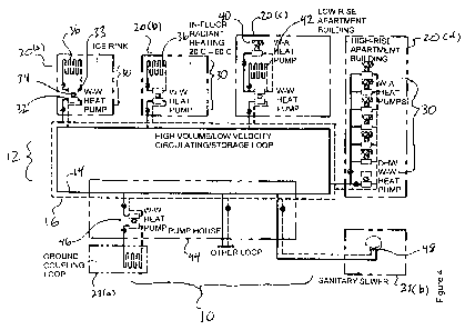
Referring now to Figure 4, the heat transfer apparatus 30 in each building 20
can
comprise one or more heat pump assemblies that can be configured to transfer
low-grade (low temperature) energy from the warm water conduit 14 into higher-
grade energy that can be used to heat the building 20. One or more other heat
pump assemblies can be configured to provide cooling for the building 20 and
reject the by-product heat to the cool water conduit 16. Yet some other heat
pump assemblies having a valve switching assembly (as shown in Figure 4 and
as will be described in detail below) can be selectively configured to provide
heating or cooling to a building 20 by drawing heat from the warm water
conduit
14 or rejecting heat into the cool water conduit 16.
Heat pump assemblies can be water-to-air or water-to-water. Water-to-air heat
pump assemblies have heat pumps that are typically small units that serve
single
rooms and can be fed directly by the DESS 10 or by a closed piping loop that
interacts with the DESS 10 through a circuit heat exchanger. The heat pumps in
the buildings 20 can be operated in heating and/or cooling mode so that the
heat
transfer to the circuit 12 is the net difference between the heating and
cooling
loads. The DESS 10 thus could replace a boiler and a cooling tower
traditionally
present in some buildings.
Each heat pump assembly comprises a pair of heat exchangers (respectively
"circuit heat exchanger" 32 and "building heat exchanger" 33,) and a heat pump
34 thermally coupled to but fluidly separated from both heat exchangers 32,
33.
The circuit heat exchanger 32 is in fluid communication with both the warm
water
conduit 14 and the cool water conduit 16. More particularly, the circuit heat
exchanger 32 has an inlet in fluid communication with the warm water conduit
14,
and an outlet in fluid communication with the cool water conduit 16 such that
water flows from the warm water conduit 14 through the heat exchanger 32 and
then to the cool water conduit 16. The heat pump 34 is arranged so that its
12
CA 02765065 2011-12-09
WO 2010/145040 PCT/CA2010/000969
evaporator is in thermal communication with the circuit heat exchanger 32 such
that some thermal energy in the warm water flowing through the heat exchanger
32 is absorbed by the working fluid in the heat pump 34, thereby cooling the
circuit water which then flows into the cool water conduit 16. The heat pump
34 is
also arranged so that its condenser is in thermal communication with the
building
heat exchanger 33 such that the thermal energy absorbed from the circuit water
is discharged into the building 20.
In the embodiment shown in Figure 4, an ice rink 20(a) requires cooling and
thus
serves as a heat source, and the following buildings require heating and thus
serve as heat sinks: a residential home 20(b), a low-rise apartment building
20(c), and a high-rise apartment building 20(d). The residential home 20(b)
requires space heating and is heated by radiant heating; a radiant heating
system 36 in each of these buildings 20(a), 20(b) is thermally coupled to the
building heat exchanger 33 of each respective heat transfer apparatus 30 and
to
the space which requires heating in each building 20(a), 20(b). The low-rise
apartment building 20(c) also requires space heating and is heated by both a
forced air system 40 and by a radiant heating system 42 both of which are
thermally coupled to the building heat exchanger 33 in this apartment building
20(c); the forced air system 40 has a water-to-air heat pump assembly which
transfers heat from a radiant hot water loop coupled to the building heat
exchanger 33 to air ducts in the building 20(c). The high-rise apartment
building
20(d) comprises a series of heat transfer apparatuses 30 to provide space
heating and domestic hot water heating to the building 20(d). The heat
transfer
apparatuses 30 which provide space heating have water-to-air heat pumps and
building heat exchangers 33 which are thermally coupled to air ducts in the
building 20(d); the heat transfer apparatus 30 which provides domestic hot
water
heating has its building heat exchanger coupled to a domestic water supply in
the
building 20(d).
The server plant 21 in the embodiment shown in Figure 4 is a pump house 44
which is thermally coupled to a geothermal ground loop 23(a) and a sanitary
13
CA 02765065 2011-12-09
WO 2010/145040 PCT/CA2010/000969
sewer 23(b). The ground loop can act as a heat source and sink and the
sanitary
sewer 23(b) can serve as a heat source. The pump house 44 comprises a heat
pump assembly 46 having a pair of heat exchangers and a heat pump thermally
coupled to but fluidly separated from both heat exchangers: a circuit heat
exchanger is fluidly coupled to the thermal energy circuit 12 and a ground
loop
heat exchanger is fluidly coupled to a fluid loop which extends into and out
of the
ground. More particularly, the circuit heat exchanger has an inlet fluidly
coupled
to the cool water conduit 16 and an outlet fluidly coupled to the warm water
conduit 14. When the ground source is used as a heat source, geothermal
energy is absorbed by the fluid pumped through the ground loop; this thermal
energy is transferred to the water flowing from the cool water conduit 16
through
the circuit heat exchanger. Additional thermal energy can be obtained from
warm wastewater discharged from the sanitary sewer 23(b); a sanitary sewer
heat transfer apparatus 48 comprises a heat exchanger which is thermally
coupled to the wastewater and which has an inlet fluidly coupled to the cool
water conduit 16 and an outlet fluidly coupled to warm water conduit 14. .
A programmable controller (not shown) can be programmed to control operation
of the heat pump in the heat pump assembly 46 so that sufficient geothermal
energy is transferred to thermal energy circuit 12 to maintain the warm water
within the desired warm water temperature range.
Referring now to Figures 5(a) to (i) and according to another embodiment, one
or
more client buildings 20 in the district can be provided with a reversible
heat
pump assembly 50 that can either draw heat from the circuit 12 or deposit heat
into the circuit 12. The heat pump assembly 50 comprises a reversible heat
pump 52, a circuit heat exchanger 56 thermally coupling the heat pump 50 to
the
circuit 12, a building heat exchanger 58 thermally coupling the heat pump 52
to
the client building 20, and a valve assembly and circulation pump 55 both
fluidly
coupled to the warm and cool conduits 14, 16 by piping 54 and which can be
configured to direct either cool water from the cool water conduit 16 or warm
water from the warm water conduit 14 through the circuit heat exchanger 56.
The
14
CA 02765065 2011-12-09
WO 2010/145040 PCT/CA2010/000969
heat pump 52 is thermally coupled to but fluidly separated from both the
circuit
heat exchanger 56 and building heat exchanger 58. The heat pump assembly 50
can be operated in a heating mode in which case the valve assembly is
configured to direct water from the warm water conduit 14 through the circuit
heat
exchanger 56 and to then into the cooled water conduit 16, and to operate the
heat pump 52 to absorb heat from water flowing through the circuit heat
exchanger 56 and to discharge heat into the building heat exchanger 58 (which
in this Figure is shown coupled to a forced air system of the building, but
can be
coupled to any building heat distribution system as is known in the art).
Conversely, the heat transfer apparatus 50 can be operated in a cooling mode
in
which case the valve assembly is configured to direct cool water from the cool
water conduit 16 through the circuit heat exchanger 56 and into the warm water
conduit 14, and to operate the heat pump 52 to absorb heat from the building
heat exchanger 58 and to discharge this absorbed heat into water flowing
through the circuit heat exchanger 56.
Figures 5(a)-(c) illustrates one embodiment of the valve assembly comprising a
pair of three-way valves 60, 62. A first three-way valve 60 is fluidly coupled
by
piping 54 to the warm water conduit 14, cool water conduit 16 and the inlet of
the
circuit heat exchanger 56; a second three-way valve 62 is fluidly coupled to
the
warm water conduit 14, cool water conduit 16, and the outlet of the circuit
heat
exchanger 56. When the heat transfer apparatus 50 is set in the heating mode
as
shown in Figure 5(a), the first three way control valve 60 is closed to the
cool
water conduit 16 but open to the warm water conduit 14 and the inlet of the
circuit heat exchanger 54 and the second three-way control valve 62 is closed
to
the warm water conduit 14 but open to the cool water conduit 16 and the outlet
of
the circuit heat exchanger 54. As a result, a water pathway is provided
through
the piping 54 for water to flow from the warm water conduit 14, through the
circuit
heat exchanger 56 and to the cool water conduit 16. When the heat pump
assembly 50 is set in the cooling mode as shown in Figure 5(b), the first
three-
way valve 60 is closed to the warm water conduit 14 but open to the cool water
conduit 16 and the inlet of the circuit heat exchanger 54, and the second one-
CA 02765065 2011-12-09
WO 2010/145040 PCT/CA2010/000969
way valve 62 is closed to the cool water conduit 16 but is open to the warm
water
conduit 14 and the outlet of the circuit heat exchanger 54. As a result, a
water
pathway is provided through the piping 54 for water to flow from the cool
water
conduit 16, through the circuit heat exchanger 56 and to the warm water
conduit
16. The circulation pump 55 is coupled to the piping 54 at the inlet of the
circuit
heat exchanger 56 and is operated to effect such flow.
The pair of three-way control valves 60, 62 can be solenoid valves which are
communicative with a controller programmed to configure the control valves 60,
62 in their respective cooling mode configuration and heating mode
configuration. Alternatively the pair of three way control valves 60, 62 can
be
manually adjustable between their cooling and heating mode configurations.
When the heat pump is off as shown in Figure 5(c), both control valves 60, 62
close one of their ports to stop flow of warm water and hence flow of cold
water
through the piping 54. Alternatively both valves 60, 62 close one of their
ports to
stop the flow of cool water and hence flow of warm water. In either position,
water can still circulate through the piping 54 via the remaining open ports.
The control valves 60, 62 can be a modulating valve which can be modulated by
a temperature sensor (not shown) in the supply conduit to the heat pump 52 or
a
refrigerant pressure controller to mix cool water discharged from the heat
pump
52 with the warm water from the warm water conduit 16 to maintain a maximum
entering water temperature or maximum refrigerant pressure.
Instead of a pair of three-way control valves, the same functionality can be
achieved by a single four-way control valve 63 as shown in Figures 5(d) to (f)
and
according to another embodiment. The four-way control valve 63 has four ports
A, B, C, and D and has a rotary actuator that switches flow so that in one
position it connects port A to port B and port C to port D. When the valve
switches to its other position, it connect port A to port C and port B to port
D.
Piping 54 is provided so that an inlet port of the circuit heat exchanger 54
is
coupled to port A, the warm water conduit 14 is connected to port B, the cool
16
CA 02765065 2011-12-09
WO 2010/145040 PCT/CA2010/000969
water conduit 16 is coupled to port C, and an outlet port of the circuit heat
exchanger 54 is coupled to port D. In a first position of the control valve 63
warm
water flows through the piping 54 and into the circuit heat exchanger 54 and
the
cool water is discharged from the circuit heat exchanger 54 into the cool
water
conduit 16. In the second position of the control valve 63, cool water is
directed
into the circuit heat exchanger 54 and warmed water is discharged to the warm
water conduit 16.
To stop flow through the heat pump, a two-way control valve 65 that closes
when
the heat pump is off is placed in either the warm or cool supply pipes.
As can be seen in Figures 5(g) to (i), two pairs of two-way control valves 64,
66
can be operated in a similar pair to the one pair of three-way control valves
60,
62 to enable the heat transfer apparatus to operate in both cooling and
heating
modes. In these drawings, the control valves 64, 64 which are open are shown
in
outline, and the control valves which are closed are shown in solid black. As
can
be seen by the arrows in Figure 5(g), a fluid pathway through the piping 54 is
defined by the opened and closed control valves 64, 66 that warm water flows
from the warm water conduit through the circuit heat exchanger 56 and to the
cool water conduit 16. Similarly, a fluid pathway is shown by the arrows in
Figure
5(h) showing water from the cool water conduit 16 flowing through the circuit
heat
exchanger 56 and to the warm water conduit 14. All control valves 64, 66 are
shown closed in Figure 5(i) thereby preventing flow through the piping 54.
Referring now to Figure 6 and according to yet another embodiment, the DESS
10 can be configured with one heat transfer apparatus 30 servicing multiple
client
buildings 20 (hereinafter referred to as a local heat transfer plant 70). The
local
heat transfer plant 70 comprises a heat pump assembly 72 having a pair of heat
exchangers 74, 76 and a heat pump 78 thermally coupled to these two heat
exchangers 74, 76. One of these heat exchangers 74 is the circuit heat
exchanger which fluidly interconnects the warm and cool water conduits 14, 16
in
the same manner as previously described, i.e. with an inlet coupled to the
warm
17
CA 02765065 2011-12-09
WO 2010/145040 PCT/CA2010/000969
water conduit 14 and an outlet coupled to the cool water conduit 16. The other
heat exchanger is the building heat exchanger 76 which is fluidly coupled to a
separate water circuit (hereinafter "building water circuit" 80). The
evaporator of
the heat pump 78 is in thermal communication with the circuit heat exchanger
76
and the condenser of the heat pump 78 is in thermal communication with the
building heat exchanger 76 such that the heat pump 78 can be operated to
transfer heat from the thermal energy circuit 12 to the building water circuit
80.
Water in the building water circuit 80 is circulated by pumps in the local
heat
transfer plant 70 to space heating systems in each building 20(e), 20(f),
20(g),
which can be a fan coil air heating system as shown in building 20(e) or a
radiant
heating system as shown in buildings 20(f), 20(g). A buffer tank 84 is fluidly
coupled to the building water circuit 80 to and allows the heat pump to run
long
enough to avoid short cycling when there is only a small load. The building
water
circuit 80 is also fluidly coupled to a domestic hot water heat exchanger 86
which
in turn is thermally coupled to a domestic hot water circuit 88. The domestic
hot
water circuit 88 includes a domestic hot water tank 90 and piping 91 which
feeds
heated water to each building 20(e), 20(f), 20(g) for domestic hot water use
in
those buildings. It can be seen that thermal energy in the thermal energy
circuit
12 is transferred to the building water circuit 80 and then to the building
heating
systems to provide space heating, and from the building water circuit 80 to
the
domestic hot water circuit to provided heated domestic water.
The thermal server plant in this embodiment is a geo-exchange server plant 94
that is similar to the pump house 44 shown in Figure 4 except that the geo-
exchange server plant 94 is thermally coupled to a ground source only.
Referring now to Figure 7 and according to yet another embodiment, the DESS
10 can be configured so that each building 20(h), 20(i), 20(j) in the district
has its
own heat transfer apparatus 30, and the thermal server plant is the geo-
exchange plant 94 as shown and described for the Figure 6 embodiment. The
heat transfer apparatuses 30 in each of these buildings 20(h), 20(i), 200) can
be
different types of space heating systems, such as a water to air heat pump
18
CA 02765065 2011-12-09
WO 2010/145040 PCT/CA2010/000969
assembly in building 20(h) used in a forced air heating system, and water-to-
water heat pump assembly in buildings 20(i) and 20(j) used in a radiant
heating
system. Alternatively but not shown, the heat transfer apparatuses 30 can also
include one or more cooling systems (not shown) comprising a circuit heat
exchanger configured to absorb heat from a building and discharge the absorbed
heat into the thermal energy circuit 12. Also alternatively, but not shown,
the
DESS 10 can include a local heat transfer plant like the plant 70 in the
Figure 6
embodiment which services other buildings in the district, such that some
buildings in the describe are collectively serviced by a local heat transfer
plant
and some buildings have their own heat transfer apparatus.
Referring now to Figure 8, and according to yet another embodiment, the local
heat transfer plant 70 and geo-exchange server plant 94 shown in Figure 6 can
be combined into a single combined plant 100 which services multiple client
buildings 20(k), 20(l), 20(m). These client buildings are each provided with a
space heating system 102 thermally coupled to the combined plant 100 and with
domestic hot water piping also thermally coupled to the combined plant 100 in
the same manner as described for the heat transfer plant 70 in the Figure 6
embodiment. In combining the heat transfer plant 70 and thermal server plant
94, the heat pump assembly 72 becomes thermally coupled to the heat pump
plant water loop instead of to the thermal energy circuit 12. The server plant
maintains its circuit heat exchanger which is in fluid communication with the
thermal energy circuit 12, and with the server plant water loop. Thus, heat
transferred from the thermal energy circuit 12 to the server plant water loop
via
the heat exchanger or from a ground source water loop via the ground heat
source heat transfer apparatus can be used to provide space heating and
domestic hot water to the buildings 20(k), 20(l), 20(m).
Referring to Figure 9(a) and according to yet another embodiment, a pair of
DESS 10(a), 10(b) (first and second DESS A and B) can be thermally and/or
fluidly coupled together by a thermal energy transfer station 110, embodiments
of
which are shown in Figures 9(b) to (d).
19
CA 02765065 2011-12-09
WO 2010/145040 PCT/CA2010/000969
The warm and cool water conduits 14, 16 in each circuit 12 (Loop A, and Loop
B)
are arranged so that the water travels in the same direction in each conduit
14,
16 to maintain similar pressure in each conduit 14, 16 at any point. The
design is
based on each circuit 12 usually having one or more server plants 21 sized to
satisfy all the client buildings 20 in the circuit 12. However server plant
capacity
and client building loads can vary from minute to minute and season to season
such that any one circuit 12 can end up with an imbalance that causes the warm
and cool pipe temperatures to drift above or below a set point. Conversely, to
achieve improved performance, an operator may want to change one circuit's
temperature in order to store energy for later use. Another reason to transfer
thermal energy from one circuit 12 to another is the need to store surplus
energy
from one server plant such as a wastewater treatment plant in a geo-exchange
server that can act a s a thermal battery.
When and if there is a thermal imbalance and thermal energy needs to be
transferred from one circuit 12(a) to another 12(b), or through a series of
circuits
12. To achieve this, a cross connection between circuits 12 is provided by the
thermal energy transfer station 110 to transfer heat from one circuit 12 to
the
other.
Three different embodiments of the energy transfer station 110 are described,
as
follows:
1. Transfer of heat between circuits 12(a), (b) within the same pressure zone
(Figure 9(b).
2. Transfer of heat between circuits 12 (a), (b) of different pressure zones
(Figure 9(c)).
3. Transfer of heat between circuits 12 (a), (b) different pressure zones and
having at least one thermal server plant in the transfer station 110
(Figure 9(d)).
CA 02765065 2011-12-09
WO 2010/145040 PCT/CA2010/000969
1. Transfer of heat between loops in the same pressure zone
Referring to Figures 9(b) and (e) to h), the transfer station 110 comprises a
warm
and cool water transfer conduit 120, 122 respectively coupling the warm and
cool
water conduits of the two thermal energy circuits 12(a). A pump 124 is coupled
to the warm water transfer conduit 120 and can be operated to flow water from
a
first circuit 12(a) to a second circuit 12 (b). The pump 124 has a Variable
Speed
Drive (VSD) so the flow rate is adjustable.
A changeover assembly 125 comprising a pair of three-way control valves 126
with associated piping and shut off valves coupled to the warm water transfer
conduit 120 allow the direction of water flow to reverse. There are four modes
of
operation based on the positions of the three way control valves 126 (open
positions of each valve 126 is shown in outline; the closed position is shown
in
solid black). Mode 1 pumps water from the first circuit 12(a) to the second
circuit
12(b) (Figure 9(e). Mode 2 pumps water from second circuit 12(b) to the first
circuit 12(a) (Figure 9(f). Mode 3 allows free flow in either direction with
the pump
off (Figure 9(g) and Mode 4 allows no flow (Figure 9(h). Mode 4 allows the
circuits 12(a), (b) to operate independently with no thermal energy transfer.
When transferring water through several circuits 12 (not shown), it is
possible to
operate only one pump 124 in Mode 1 or 2 at one transfer station 110 and have
the other transfer stations 110 in Mode 3.
A shut off control valve 128 is provided on the cool water transfer conduit
122 to
stop flow of water between the circuits 12(a), (b). The shut off control valve
128
is a secondary isolation means that would close off in Mode 4 to ensure that
there is no flow through the cool water transfer conduit 122 due to pressure
differences between loops that are themselves cross-connected other loops. The
shut off control valve 128 is a modulating type that can control the flow
based on
relative pressures in the two circuits 12(a), (b).
21
CA 02765065 2011-12-09
WO 2010/145040 PCT/CA2010/000969
2. Transfer of heat between different pressure zones
Referring to Figure 9(c) and for circuits 12(a), (b) operating at different
pressures,
the transfer station 110 transfers thermal energy between circuits 12(a), (b)
without transferring water. The transfer station 110 comprises a liquid-to-
liquid
heat exchanger 112 with a first and second heat transfer zone that is
thermally
coupled but fluidly isolated, and piping that fluidly couples the warm and
cool
water conduits of each circuit 12(a), (b) with the first and second heat
transfer
zones of the heat exchanger 112. Transfer pumps 114, 116 are providing on the
piping coupling each circuit 12(a), (b) to the heat exchanger 112 and can be
operated to flow water from each circuit 12(a), (b) respectively through the
heat
exchanger such that heat can be transferred in the heat exchanger 112 from the
warmer circuit to the cooler circuit.
The heat exchanger 112 is a stainless steel, cleanable plate, counter-flow
heat
exchanger that are able to obtain an approach of 1 Celsius degree. That is,
one
fluid exits the heat exchanger 112 within 1 Celsius degree of the other
fluid's
entering temperature. The transfer pumps 114, 116 pump the fluid from the cool
water conduit 16 to the warm water conduit 14 in each circuit 12(a), (b). This
flow
can be reversed so that the transfer pumps 114, 116 pump water from the warm
water conduit 14 to the cool water conduit 16 by using the changeover assembly
for the pumps used for scenario 1 (not shown).
Since pressure control of the system may be in one loop but not the other,
there
is optionally a booster pump 118 and associated piping for an increase in
pressure, or a PRV if a decrease in pressure is needed.
3. Transfer of heat between different pressure zones and a server in one
station
Referring to Figure 9(d) a transfer station 110 similar to that shown in
Figure 9(c)
is provided additionally with a pair of server plants 130 each coupled to the
respective piping feeding each side of the heat exchanger 112. This
22
CA 02765065 2011-12-09
WO 2010/145040 PCT/CA2010/000969
arrangement integrates the heat exchanger 112 into the server plant building
and
can simplify the pumping and control through the sharing of equipment that
provides heat transfer with equipment that is a source or sink. Although each
server plant is shown with an exemplary ground source heat source and sink
131, the server plant 130 can be thermally coupled to other heat source and
sinks as described above.
A typical arrangement would be one or more energy source/sinks such as geo-
exchange heat pumps connected directly to a high pressure upper loop A and
another set connected directly to a low pressure lower loop B. Heat exchangers
between the high pressure and low pressure loops A, B with the capacity of one
set of heat pumps would allow all the heat pumps to serve either the upper or
lower loop. This arrangement would also allow the two loops to operate
independently or for heat to be transferred from loop to loop without use of
the
heat pumps.
Figure 10 shows a photograph of a district with the DESS 10 shown overlaid in
illustration. The DESS 10 includes a waste water heat recovery source 23,
residential buildings 20 (client heat sink), an ice arena 20 (client heat
sink), and
school, pool and green house loads 20. The solid line indicates the warm and
cool water conduits of the thermal energy circuit. The dashed lines indicate
high
temperature delivery conduits.
Figure 11 is a block diagram which explains how energy can be managed and
balanced from multiple heat sources through the DESS 10, and how water can
be recovered where available as a thermal transport medium of the DESS 10.
According to another embodiment and referring to Figure 12, the DESS 10
includes a grey water injection assembly 150 for flowing grey water from a
grey
water source 152 into the thermal energy circuit 12 and transferring at least
some
of this water to client buildings for certain domestic water uses.
23
CA 02765065 2011-12-09
WO 2010/145040 PCT/CA2010/000969
The term "grey water" means non-potable water that does not meet drinking
water standards but can be used by a client building for certain purposes such
as
toilet flushing, exterior washing or irrigation.
In this embodiment, the thermal energy circuit 12, as well as delivering
thermal
energy to client buildings 20, is capable of providing grey water distribution
to the
client buildings 20. The grey water can be used for toilet flushing and
irrigation,
thus dramatically reducing the consumption of potable water. Although the DESS
is normally a closed loop, the grey water injection assembly 150 makes the
DESS 10 partially open and therefore requires that the piping in circuit 12 be
10 suitable for an open system using suitable materials such as plastic, non-
ferrous
metals and stainless steel.
The grey water, which is clean effluent from a sewage treatment plant, must
meet certain standards to prevent build-up of dirt or growth in the circuit 12
and
especially in the heat exchangers. There are also standards to be met for
health
reasons. However the required standards are much lower than those for potable
water.
The injection of grey water does increase the flow of water in the DESS but
the
grey water demand is much less than the water flow required for the energy
transfer. Therefore, the pipe size usually does not need to be increased to
accommodate the incoming flow of grey water.
The components of the grey water injection apparatus 150 are described
A grey water supply conduit 153 fluidly couples the grey water source 152 to
piping in a thermal server plant 21; in this case the grey water supply
conduit 153
is coupled to a warm water supply conduit 154 as the grey water is warm and
can contribute some thermal energy to the circuit 12; however, the grey water
supply conduit 153 can alternatively be coupled to a cool water supply conduit
156 especially if the grey water is cool.
24
CA 02765065 2011-12-09
WO 2010/145040 PCT/CA2010/000969
The grey water flowing the grey water supply conduit 153 first passes through
a
filtration device (not shown) to ensure it meets required standards for
health,
particulate concentration and biological growth potential. A pressure control
device 156 is coupled to the grey water supply conduit 153 downstream of the
filtration device and serves to regulate the water pressure within the circuit
12. In
particular, the pressure control device 156 has a standard pressure boosting
pumping system that increases the pressure of the grey water to higher than
the
DESS 10. The pumping system consists of an arrangement of pumps control
valves and cushion tank that delivers a variable flow of water to a set
pressure.
The set pressure of the pumping system is the required pressure for the DESS
10. The control device 156 can also include one or more PRV to reduce water
pressure in the circuit. The pressure control device can further comprise at
least
one control valve and a cushion tank fluidly coupled to the pump and operable
to
vary the flow rate of grey water to the warm water conduit.
The warm supply conduit 14 feeding each client building 20 is sized to take
both
the heat pump flow and the simultaneous grey water flow. For a typical house
the
DESS supply would be 1" diameter and when the grey water is added it would be
1 '/" diameter. A buried take-off conduit 158 from the building's warm supply
conduit 159 would feed a water meter 160 to measure the grey water use and
then the water would connect to an irrigation system and toilet flushing
system
(not shown) of the building 20.
Use of grey water by any client building 20 could reduce the pressure in the
entire circuit 12 and the pressure control device 156 would sense the pressure
drop and introduce new grey water into the DESS 10 to maintain the set
pressure.
As noted above, the DESS 10 is a modular low grade thermal energy network
linking diverse heat sources and clients through a low temperature, water-
based
piping system, and providing both heating and cooling to buildings within the
district. The DESS 10 is applicable to residential, institutional, commercial
and
CA 02765065 2011-12-09
WO 2010/145040 PCT/CA2010/000969
industrial districts. Any source of heat that can be transferred to low
temperature
water can be integrated into the DESS 10 including such diverse sources as geo-
thermal, geo-exchange, ground water, surface water, waste water, refrigeration
systems, ice rinks, solar collectors exhaust air streams, diesel generators,
and
chimneys. The DESS 10 captures this low grade heat from these heat sources
and distributes it to clients that, by using heat pumps in heat transfer
apparatuses, convert the low grade thermal energy to a higher grade for
heating
buildings and servicing water, or return heat to the low grade system for air
conditioning.
The thermal energy circuit 12 provides both an energy delivery function as
well
as an energy storage function, and these two functions enable sharing of
thermal
resources, and through diversity, a reduction in required heat source size.
The
temperature of the piping used in the thermal energy circuit 12 of the DESS 10
is
close to the ground temperature and therefore does not need to be insulated.
The piping can be high density polyethylene (HDPE which is very low cost
relative to other piping systems and can be used because of the low operating
temperature.
Integrating conventional district energy solutions into existing roads and
buildings
can be a logistical challenge that frequently requires significant capital
expenditures before integration can be completed. Advantageously, the modular
nature of the DESS 10 and the relative ease of installing and tapping into
HDPE
piping allow for gradual expansion and offer an early return on capital
expenditures.
The DESS 10 can be characterized by use of energy reserves which are sources
and/or sinks where energy can be drawn from or stored for future use, such as
ground, (static) aquifers, lakes, and oceans. Other sources include those
sources
that have limited storage capability, variable output range and must be reused
in
a short period of time. These sources may include large energy recovery
sources
where heating and cooling need to be drawn off to be used in other areas, such
26
CA 02765065 2011-12-09
WO 2010/145040 PCT/CA2010/000969
as waste water effluent, air conditioning, ice rinks, industrial processes,
and co-
generation processes. Once the available sources are characterized, loads are
matched to the sources and multi-loop, hybrid systems developed for combined
residential, commercial and industrial applications optimizing the
efficiencies of
the buildings connected to the DESS 10, minimizing the waste heat rejected to
the environment, and reducing peak loads by preconditioning the DESS 10.
The heat captured from the heat sources 23 can also be stored, and storage
options can be diverse, including ground sources, thermal cistern storage,
system infrastructure or pools. The warm and cool water conduits 14, 16 offer
a
temperature differential to significantly increase the efficiency of the heat
pumps
used in the DESS 10. By pulling warm water from the warm water conduit 14 for
heating and returning the now much cooler water to the cool water conduit 16
it
becomes possible to offset loads. Some systems are typically running in
heating
mode and some in cooling; the DESS 10 offsets these loads which minimizes the
overall requirement for the district. Instead of the primary sources like geo-
exchange being the primary heat source or sink they take on a greater role as
a
tool to balance the energy requirements of the DESS 10 and as a large storage
for seasonal loads.
As shown in Figure 12, the DESS 10 can also be used as a conveyor of
reclaimed water from a wastewater treatment plant or other process wherein
water is recovered. This increases the efficiency of heat recovery from these
sources and, subject to the water quality meeting local health and
environmental
regulations, the reclaimed water may be used to reduce demand for potable
water by using the reclaimed water for toilet flushing, irrigation, stream
augmentation and other water services not requiring potable drinking water.
The DESS 10 can also be used as a vehicle to help manage storm water by
filtering it and, depending on its temperature, routing it through the warm or
cool
water conduits 14, 16. In the event of a major storm surge the DESS 10 may be
able to help divert excess storm water in one area of a community to another
27
CA 02765065 2011-12-09
WO 2010/145040 PCT/CA2010/000969
area in the community that is better able to handle excess storm water. The
DESS 10 addresses the problems of comparable temperature systems, and
offers an efficient model for an expandable district system. It utilizes a
relatively
low temperature warm and cool water conduits 14, 16 in the form of a loop as
the
primary distribution system. Multiple loops of varying temperatures can be
connected and balanced to maximize the efficient transfer of energy from one
loop or network to another. In addition to developing large centralized
thermal
energy systems, smaller localized thermal energy balance transfer stations as
shown in Figure 9 ("mini-plants") can be used to add new sources of thermal
energy, and manage and balance thermal energy among various loops and
segments of loops. This latter approach helps to match the capital costs of
the
DESS 10 with the current phase of development or the tax base under
consideration, while allowing for a more scalable DESS 10 that can easily grow
with the development or expansion into an existing community. By using small
mini-plants at large sources and sinks it is possible to capture low grade
heat
from the environment or equipment and balance the warm and cool water
conduits 14, 16. This approach also allows for ease of expanding the DESS 10,
and each of the plants can divert energy to other parts of the DESS 10. The
interconnectivity increases the stability of the DESS 10 and allows for easy
expansion.
Mini-plants may contain any number of heat pumps, pumps, heat exchangers
and storage tanks to balance and control the efficient collection, storage and
transfer of thermal energy from one loop to another. These mini-plants also
help
in preconditioning the circuit 12 and also maximizing the efficient delivery
of
excess thermal energy to storage locations throughout the circuit 12. The
storage
locations may be storage tanks, which can be non pressurized, plastic,
fibreglass
or metal and can be located inside the mini-plant or buried outside. Multiple
heat
pumps allow the plant to be expanded as the required capacity increases. The
mini-plants may be modular, factory built and tested and the equipment can be
housed in a concrete chamber, partly buried, or a low height factory sheet
metal
enclosure with access panels similar to rooftop equipment. In the case of
larger
28
CA 02765065 2011-12-09
WO 2010/145040 PCT/CA2010/000969
buildings such as multifamily residences or commercial buildings, the
miniplants
can be incorporated into the buildings.
From an optimization standpoint, available energy sources are evaluated on a
site-by-site basis and the DESS 10 is designed around the available sources to
minimize the costs and maximize the sustainability of the DESS 10. A DESS 10
can also be used to reduce the overall energy required for a community's
heating, cooling, and domestic hot water, by balancing the energy required for
heating with the energy rejected from cooling, thereby reducing the overall
cost
of the infrastructure. The heat rejected from buildings in one area or
gathered
from one or more source or storage location can be transferred to where
heating
is required. In this method the load is shared across the district. Similarly,
cool
water rejected from buildings in heating mode or gathered from one or more
sources or storage locations will be used to cool buildings more efficiently.
This
sharing of heating and cooling energy reduces the overall energy consumption
in
the network, and reduces the amount of additional sources required.
A series of special components and sub assemblies can form part of the DESS
10 and may include one or more of the following:
= Low head high flow in-line pump arrangements.
= HDPE venturi injection tees for source or client connections to impart
kinetic
energy to the DESS mains water flow and allow one pipe or two pipe operation.
One pipe operation allows one of the two pipes to be shut down while the
system
still operates at the cost of lower efficiency.
= Two or Four pipe building connection and valve assembly to take advantage of
one or two pipe DESS operation.
= In-ground non pressurized stratified heat storage tanks with water, or water
and
rock, in-fill.
29
CA 02765065 2011-12-09
WO 2010/145040 PCT/CA2010/000969
= Mini-plants to connect to a variety of loads, sources and the DESS and
arranged to deliver, withdraw, store energy and control the transfer of energy
to
and from other mini plants and zones in the DESS network.
= Energy metering device and software for flow, heating and cooling.
= Software for network DESS flow and temperature control system.
= Accessible, in-line, remote temperature and pressure monitoring devices.
In North America the most available thermal energy sources are typically low
temperature sources, for which heat pumps are required to boost the level of
heating or cooling. Many heat pumps are able to get a coefficient of
performance
over 5.5 when placed in the DESS 10. This has the effect of reducing the
overall
building energy consumption for heating and cooling by over 80%, and the
overall building energy consumption by over 45%. By minimizing the overall
electrical energy consumption in the district, other alternative energies
become
more feasible, further encouraging and increasing the sustainability of the
project. When considering the staging of distributed energy sources and
maintaining the flexible mechanical systems there are two options: converting
all
energy sources to a common high temperature (may not be feasible for smaller
low grade energy sources) or distributing at ambient temperatures. When
retrofitting a neighbourhood, this latter strategy can combined with mini-
plant
energy centres containing heat pumps that can be used to boost the delivery
temperature up to 135 F-180 F, depending on the optimal integration
requirements.
This strategy maximizes the efficiency of a low cost and low energy loss
ambient
temperature distribution system with a high temperature delivery system, that
simplifies integration when space in an existing mechanical room cannot be
found. Because high temperatures are only used for short distances, line
losses
can be limited and energy delivered can be better managed, reducing the
overall
life cycle costs of the DESS 10, while simplifying integration requirements.
CA 02765065 2011-12-09
WO 2010/145040 PCT/CA2010/000969
The thermal energy circuit 12 represents a potentially significant thermal
energy
storage system, as a result excess thermal energy can be stored in the circuit
12
by adjusting the average temperature of one of the water conduits 14, 16 in
the
circuit 12. This ability to store and adjust the water temperature, or
preconditioning of the water temperature, can have a number of potential
benefits, including peak shaving and load matching. Load matching is done by
monitoring both the outside air temperature and building design temperatures
and raising or lowering the circuit 12 temperature to better match the
expected
heating and/or cooling loads, thus allowing the equipment to run more
efficiently
and improve the performance of the heat pumps. Peak shaving is accomplished
by pre-conditioning the circuit 12 ahead to match expected loads prior to
reaching a threshold price for commercial and/or residential electricity
prices
enabling the DESS 10 to perform peak electricity shaving or peak shaving. By
pre-conditioning the circuit 12 ahead of peak energy costs for electricity,
fewer
pumps and heat pumps need to run during these hours and those that do run will
run more efficiently. This will reduce the peak load demand costs for
buildings
with demand load charges and potentially significantly reduce the cost of
operation.
Although the circuit 12 represents a storage vessel for thermal energy,
additional
storage can be added in terms of storage tanks in the district or pre-heat
tanks in
the building. For example, a preheat tank can be provided as part of the DESS
10.
Another key advantage of the DESS 10 is the use of modular district energy.
The
DESS 10 provides infrastructure integration which may integrate multiple
sources
(both sustainable and fossil fuel based), manage overall energy demands and
storage requirements across an entire district; and is able to integrate
multiple
communities and manage the demands and storage capabilities across an entire
"grid" or region. The distribution and delivery system integrates low
intensity/temperature distribution with high temperature building connection
requirements to minimize the cost of retrofitting building systems; provides
the
31
CA 02765065 2011-12-09
WO 2010/145040 PCT/CA2010/000969
benefits of low/ambient temperature distribution with the needs of existing
building systems for higher temperature integration; and provides building
connections to meet the needs of existing building systems for either low
grade
thermal energy or higher grade thermal energy.
The DESS 10 provides reliability in that when mini-plants are combined with a
warm and cool pipe system in a "grid" framework, individual mini plants can be
taken off line for service without compromising the DESS 10 as a whole.
Interconnecting modules within the DESS 10 cause improved reliability and
retrofitting costs are reduced by best matching the type of building
connections to
the needs of the building. The DESS 10 can use a plurality of pressure zones
and thermal energy transfer zones. Mini-plants provide ideal facilities to
integrate
different pressure zones within a community or the DESS network. Adjacent
areas of the network have their own loops cross-connected with transfer pumps
and among two or more zones. To keep pressure in the pipes to a reasonable
level that allows for the use of lighter duty pipes, where adjacent loops have
substantially different elevations, the cross connections may be by heat
exchanger. As discussed earlier, mini-plants also allow for the balancing,
management and transfer of energy from one zone to another, and can be set up
and controlled to route thermal energy across multiple zones. Energy balancing
can be provided given that alternative energy sources have both daily and
seasonal variations, making it very difficult or cost prohibitive to build an
entire
district energy system based on one source, alone. The modular nature of the
DESS and its ability to integrate multiple sources reduces the cost of any
given
source by providing the overall energy demand of the community is met; the
energy provided is sustainable and these sustainable sources can be used to
increase density of potential redevelopment.
Because high temperatures are only used for short distances, line losses can
be
limited and energy delivered can be better managed, reducing the overall life
cycle costs of the DESS, while simplifying integration requirements. To
maximize
the efficiency of these higher output temperature heat pumps it may be
32
CA 02765065 2011-12-09
WO 2010/145040 PCT/CA2010/000969
necessary to pre-condition the DESS circuit temperatures to provide a slightly
higher input temperature to these higher output temperature heat pumps. This
is
particularly important when retrofitting a DESS into an existing community
where
there are existing buildings with specific heating constraints and a desire to
reuse
as much of the existing building heating and cooling system as possible. This
also means that the overall loop temperature can be more dynamically managed
to reflect individual building heating and cooling requirements, thus reducing
energy supply costs and maximizing the performance with which energy is
transferred into each building on the network. Loop temperatures can be more
accurately controlled to reflect the needs of the buildings for either heating
and
cooling. In building equipment can be controlled to only pull what is needed.
33