Note : Les descriptions sont présentées dans la langue officielle dans laquelle elles ont été soumises.
CA 02765076 2017-01-19
NARROW LINED MODULAR FLOORING ASSEMBLIES
Field
The present invention relates to a modular flooring assembly including a
flooring component adhered to a tray substrate.
Background
United States Patent Publication 2007009469 teaches the use of a tray
substrate
and a flooring component to create a floating tile structure. The trays
interlock with
each other as demonstrated in Figure 17 of that specification. United States
Patent
7,197,855 teaches the use of a tray substrate with a flooring component
attached that is
interlocked as well.
Both of these systems provide for interlocks between the tray that completely
extend from the side of the tray. Generally these interlocks set the size of
the gap
between the trays. One can make the gaps narrow by reducing the size of the
locking
mechanisms. However, reducing the size of the locking mechanism reduces the
strength of the lock and also leads to breakage of the interlocks during
installation due
to their small size.
There exists therefore a need for a tray substrate system which can provide
strength and size of the interlocking mechanism yet maintain a small gap
between the
tiles attached to the interlocked tray substrate.
Summary
The present invention relates to a modular flooring assembly including an
optional flooring component such as a tile adhered to a tray substrate. The
modular
flooring assembly may be interconnected with additional modular flooring
assemblies
to form a modular floor suitable for most flooring applications. The flooring
1
CA 02765076 2017-01-19
component may comprise tile or wood or other materials commonly used in
flooring
applications. Conventional fill-in grout or a snap-in grout may be used with
the
modular flooring assemblies.
Certain exemplary embodiments can provide a component of a flooring system
comprising: a flooring component, an adhesive, a tray substrate comprising a
tray
substrate surface which is an upward facing horizontal surface having a tray
substrate
surface perimeter, a tray substrate bottom with a padding attached to the tray
substrate
bottom, a plurality of tray substrate vertical tray edges which protrude
upward and
extend along the tray substrate surface perimeter, a plurality of tray
substrate edges
defining an outside perimeter of the tray substrate, the tray substrate edges
having a
plurality of upward tabs comprising a surface and a valley and a plurality of
downward tabs comprising a surface and a lip, wherein the downward tabs are
recessed at portions thereof under the upward facing horizontal tray surface,
and said flooring component is adhered to the tray substrate surface with the
adhesive.
Certain exemplary embodiments can provide a component of a flooring
system comprising: a tray substrate having a tray substrate surface which is
an
upward facing horizontal surface, a tray substrate bottom with a padding
attached to
the tray substrate bottom, a plurality of vertical tray edges which protrude
upward
and extend around a perimeter of the tray substrate surface, a plurality of
tray
substrate edges defining an outside perimeter of the tray substrate, the tray
substrate
edges having a plurality of upward tabs and a plurality of downward tabs,
wherein
the upward tabs have a surface and a valley, and the downward tabs have a
surface
and a lip and wherein the downward tabs are recessed at portions thereof under
the
upward facing horizontal tray surface.
2
CA 02765076 2017-01-19
Disclosed in this application is a component of a flooring system comprising
which is a tray substrate comprising a tray substrate surface which is an
upward facing
horizontal surface having a tray substrate surface perimeter, a tray substrate
bottom
with a padding attached to the tray substrate bottom, a plurality of tray
substrate
vertical tray edges which protrude upward and extend along the tray substrate
surface
perimeter, a plurality of tray substrate edges defining an outside perimeter
of the tray
substrate, the tray substrate edges having a plurality of upward tabs
comprising a
surface and a valley and a plurality of downward tabs comprising a surface and
a lip,
wherein at least a portion of the downward tab is recessed under the upward
facing
horizontal tray surface. It is further disclosed that the tray substrate may
have a
flooring component adhered to the tray substrate surface with an adhesive.
It is further disclosed that the flooring component may be selected from the
group consisting of tile, stone, marble, wood, ceramic tile, porcelain tile,
and granite.
It is also further disclosed that the flooring component may be smaller than
the tray
substrate surface. It is also further disclosed that the tray substrate
vertical tray edges
may run the entire perimeter of the tray substrate surface.
Brief Description of the Drawings
FIG. 1 is a perspective view of the tray substrate.
FIG. 2 is a perspective view of a flooring component.
2a
CA 02765076 2011-12-08
WO 2010/144631
PCT/US2010/038049
FIG. 3 is a perspective view of the prior art interconnect upward facing tab.
FIG. 4 is a perspective view of the prior art interconnect upward and downward
facing tabs.
FIG. 4A is a perspective view of the prior art interconnect upward and
downward
facing tabs.
FIG. 5 shows three modular flooring assemblies assembled.
FIG. 6 is a perspective view of the recessed interconnect.
FIG. 7 is a side view of the recessed interconnect.
FIG. 8 is a bottom view of the recessed interconnect.
FIG. 9 is a bottom view of the recessed interconnect.
FIG. 10 is a bottom view of the recessed interconnect with grout holders on
the
perimeter.
FIG. 11A is a cross section of two tray substrates aligned to interlock.
FIG. 11B is a cross sections of the two substrates of FIG 11A that have been
assembled and interlocked.
FIG. 12 is the back of the tray showing the pad.
3
CA 02765076 2011-12-08
WO 2010/144631
PCT/US2010/038049
Detailed Description of The Preferred Embodiments
The present invention relates to a modular flooring assembly including a
flooring component adhered to a tray substrate. The modular flooring assembly
may
be interconnected with additional modular flooring assemblies to form a
modular
floor suitable for most flooring applications. The flooring component may
comprise
tile or wood or other materials commonly used in flooring applications. The
tray
substrate comprises tabs, which provide for the tray substrates to interlock
with tabs
from an adjacent tray substrate. The fully assembled modular floor provides
the
appearance of a conventional floor. Fill-in grout or a snap-in grout may be
used with
the modular flooring assemblies.
The modular floor may be quickly disassembled and does not damage the sub
floor, as the modular floor is not typically attached to the sub floor by
adhesives,
grout compounds, or other fastening means. Further, the modular floor may be
installed over an existing sub floor without the installation of a concrete
backer board,
which is commonly used in ceramic tile installation.
The tray substrate holds the flooring component on its tray surface. The tray
surface is an upward facing horizontal surface with vertical tray edges which
protrude
upward around the perimeter of the tray surface and outline the perimeter of
the tray
surface.
The tray surface may be generally flat, or may contain a pattern designed to
enhance adhesive performance between the tray surface and the flooring
component.
The tray surface pattern may be designed to complement the bottom of the
flooring
component; for example, tiles may have different mold patterns on their bottom
depending upon the manufacturer's design. The tray surface may also be solid,
or
may have holes therein. The holes may be added in appropriate locations to aid
in
moisture evaporation without compromising adhesive performance.
The vertical tray edges are designed to ensure substantially exact, or exact,
alignment of the flooring component with the tray surface, and help provide a
barrier
to ensure adhesive can be applied over the entire bottom of the flooring
component
4
CA 02765076 2011-12-08
WO 2010/144631
PCT/US2010/038049
without the adhesive being pushed or flowing into the tab areas. If adhesive
is
allowed to enter the tab areas, their interlocking connection may be
physically
impaired by adhesive residue. The vertical tray edges do not have to run the
entire
perimeter of the tray substrate, but preferably should run the entire
perimeter of the
tray substrate. The inside of the vertical tray edges define an area smaller
than the
perimeter of the tray substrate. The flooring component is set inside the wall
defined
by the vertical tray edges and is adhered to the tray surface defined by the
inside wall
of the vertical tray edges.
By their vertical orientation, the tray edges positionally hold the flooring
component and, in combination with the adhesive, reduce lateral movement. The
tray
edges may provide a further surface for the adhesive to adhere the side of the
flooring
component. The tray surface joins to the bottom of the flooring component via
the
adhesive and the tray edges join to the sides of the flooring component via
the
adhesive. The combination of the adhesive on the tray surface and the adhesive
on
the tray edges provide a secure hold for the flooring component. This insures
that the
flooring component is locked down to the tray substrate, and the flooring
component
does not slip or move.
The size of the tray substrate and the flooring component are strictly
controlled to insure that the flooring component fits securely in the tray
substrate.
The flooring component should just fit onto the tray surface and rest snugly
against
the vertical edges. The flooring component should be slightly smaller than the
tray
surface defined by the vertical tray edges.
The present invention achieves significant advantages. A tray with four
vertical tray edges, improves the structural rigidity of the tray. The four
tray edges
prevent adhesive from pushing into the interlocking tabs. In other systems,
the
adhesive can push into the tab area causing interference with the other tile.
The four
tray edges help align the flooring component to the tray, which improves
assembly
ease and quality. In other systems, the flooring surface is not constrained
and
therefore must be held in place until the adhesive has cured.
CA 02765076 2011-12-08
WO 2010/144631
PCT/US2010/038049
There are upward and downward facing tabs located on all sides of the tray
substrate. The upward and downward orientation is based upon the tray bottom
and
the upward facing tray surface. The upward and downward tabs should alternate
on
each edge of the tray substrate, but they do not have to alternate. For
example, there
could be two downward tabs, one upward tab and two downward tabs. For most
flooring applications, the use of 6, 8, or 10 tabs per edge, half of each
orientation,
provide satisfactory performance. In other embodiments, there may be fewer or
additional tabs. The tabs do not necessarily have to alternate. In practice,
it has been
found that the number of tabs be in multiples of four.
The upward tab comprises a surface and a valley. The shape of the surface
could be convex or flat or spiked. The downward tab includes a surface and a
lip.
The shape of the surface may be concave. As the downward tab is urged against
the
upward tab, the upward tab flexes as the lip slides over the convex surface
and into
the valley, such that the lip snaps into the valley and the concave surface
presses over
the convex surface. This provides a connection with sufficient rigidity to
create a
composite floor made of multiple modular flooring assemblies.
In order to provide the narrow grout line, or gap between the two
interconnected tray substrates, the downward facing tab does not extend from
the side
of the tray substrate. Rather, the downward tab extends from a recessed area
in the
side of the tray substrate. The length of the recessed area as measured along
the side
of the tray substrate is at least slightly longer than the upward facing tab
so that the
upward tab can fit into the recessed area and under the tray surface, and that
at least a
portion of the valley of the downward tab is aligned underneath the horizontal
tray
surface. Alternatively stated, at least a portion of the downward tab is
recessed under
the tray surface. In one embodiment, a portion of the lip of the downward tab
is
directly beneath the vertical tray edge with the valley underneath the
horizontal tray
surface. In another embodiment only the upward facing tab is recessed into the
tray
edge. In yet another embodiment, both tabs are recessed into the tray edge or
underneath the horizontal surface.
6
CA 02765076 2011-12-08
WO 2010/144631
PCT/US2010/038049
The modular flooring assembly is designed such that even if one or more tabs
are broken on a given side, the tray substrates will still interlock. This
also allows the
modular flooring assemblies to be cut to a specific size and to still
interlock.
The interlocking tabs may be positioned such that the modular flooring
assemblies are offset supporting various decorative patterns.
The interlocking tabs on one modular flooring assembly need not be perfectly
aligned with the other modular flooring assembly to allow "fine-tuning" of the
relative
tile position.
The bottom of the tray, i.e., opposite of the tray surface, is designed as the
foundation of the system. The bottom may include structural webbing to
strengthen
the tray bottom ensuring the tray surface remains relatively flat.
The bottom of the tray may also include an optional non-skid and noise
deadening padding of an over-molded, rubber-like material, such as
thermoplastic
rubber or thermoplastic elastomer. A particularly preferred thermoplastic
elastomer is
SANTOPRENE . The padding provides a cushion for the flooring system. The
padding also provides a non-skid element that prevents the flooring system
from
sliding on the underlying flooring material. The padding also provides some
level of
flex in the presence of underlying floor surface imperfections or heavy
surface loads.
The padding also helps reduce vibration transmission, thus providing a sound-
deadening function. This padding may be adhered to the tray or overmolded.
As described above, various type of grout may be used in the present
invention, including the snap-in grout or a fill-in grout compound that is
spread into
the gaps between neighboring trays.
Fill-in grouts may also be used with the trays. Fill-in grouts may be packaged
in a powdered or granular form. The user mixes the powder or granules with a
liquid
to form a plastic material that is spread in between the modular flooring
assemblies.
Other fill-in grout compounds are packaged in a ready to spread form. The
modular
flooring assemblies are snapped together and the fill-in grout material is
used to fill
7
CA 02765076 2011-12-08
WO 2010/144631
PCT/US2010/038049
the space between the modular flooring assembly. The fill-in grout material
must
remain semi-flexible once cured since the floor "floats." The separate grout
material
must also have good adhesive qualities to ensure the material adheres to the
sides of
the modular flooring assemblies. Acrylic, urethane, epoxy, and latex modified
grouts
are suitable.
The flooring component may comprise tile, stone, marble, wood, or other
conventional flooring materials. The flooring component could be a ceramic or
porcelain tile, a natural stone product like marble or granite, or could be a
wooden
product.
The flooring component is adhered to the tray surface and tray edges using a
variety of commercially available adhesives. Suitable adhesives for use with
the
present invention include a two-part epoxy using a methacrylate material,
silicone,
rubber based and urethane based. Other urethane adhesives may also be
utilized. The
specific selection of the adhesive will depend on the nature and properties of
the
flooring component. The methacrylate adhesive is preferred for ceramic tile.
The
tray edges define a space to receive the flooring component.
The present invention, by using a snap-in grout that is not permanently
integrated with the tray, achieves advantages. The consumer may choose from
among
many different snap-in grout colors. Damaged snap-in grout can be easily
replaced.
Snap-in grout may also be changed to reflect different decorating tastes.
Finally,
flexibility is provided to either use snap-in grout or a fill-in grout.
The tray may be made using injection molding of a suitable plastic resin.
High impact polystyrene is preferred, but other plastic resins including
polypropylene
and ABS ¨ acrylobutadiene styrene may be used.
The padding of the non-skid and noise deadening material may be a
thermoplastic rubber, thermoplastic elastomer, or other softer plastic
material
including SANTOPRENE . The padding can be over-molded or otherwise attached
to the base of the tray. An adhesive is applied between the tray surface and
the
bottom of the flooring surface.
8
CA 02765076 2011-12-08
WO 2010/144631
PCT/US2010/038049
Multiple adhesive materials and application patterns can be used depending
upon the combination of plastic resin used for the tray, the flooring
material, and the
profile of the flooring material. For tile applications, adhesive is applied
to the
ridgelines on the bottom of the tile to maximize contact with the tray
surface.
Robotics may be used to improve the precision and efficiency of the assembly
process. Robotics may also be used to package and palletize the finished
products.
The modular flooring assemblies of the present invention may be used in
almost any sized embodiment, including 152.4 mm (6-inch), 165.1 mm (6 1/2-
inch),
304.8 mm (12-inch), and 330.2 mm (13-inch) embodiments. The modular flooring
assemblies have a square or rectangular shape. The square shaped modular
flooring
assemblies have four sides of equal length. Other sizes may be used, however
these
sizes are generally used in the flooring industry. Further, a combination of
the 152.4
mm (6-inch) and 304.8 mm (12-inch) modular flooring assemblies may be used in
combination to provide a unique appearance. The present invention may be
further
modified to include other combinations of different sized modular flooring
assemblies.
During use of the present invention, the modular flooring assemblies are
snapped together to form an overall flooring surface. The fill-in grout
material may
be applied between the modular flooring assemblies, or the snap-in grout may
be
installed. In order to accommodate different rooms of varying sized and
shapes, the
modular flooring assemblies can be cut using a wet saw if tile or stone is the
flooring
component or using a table or a circular saw for wooden flooring components.
The underlying flooring surface should be free of major surface variations,
but
need not be in perfect condition. No special floor preparation is required to
ensure the
tiles are fixed since the interlocking modular flooring assemblies will
"float" and flex.
The system can be installed directly on top of finished wood, linoleum, other
tile,
concrete, plywood, or a variety of other flooring systems. The modular
flooring
assemblies can be installed on top of padding or other underlayment material
if an
additional measure of insulation or padding is desired. The modular flooring
assemblies can be installed on top of radiant-type heating systems as well.
9
CA 02765076 2017-01-19
The present invention will now be described with reference to the Figures
where
like numbers refer to like components in other figures. Each time a component
is
mentioned, its number is used so if it is not present in a given figure it can
be found in
another figure:
FIG. 1 shows tray substrate 100 having a tray surface 110 with vertical tray
edges 160. The tray surface 110 receives the flooring component shown in FIG 2
600, which in this embodiment is a ceramic tile.
FIG. 2 shows the flooring component 600. A top surface 605 of the flooring
component 600 forms the floor surface. A bottom surface 610 of the flooring
component 600 is adhered to the tray surface 110 by an adhesive. Although in
this
embodiment the flooring component 600 is a ceramic tile, the flooring
component may
be made from any flooring material.
Raised vertical tray edges 160 of the tray surface 110 help secure the
flooring
component 600 and prevent adhesive from leaking from the tray surface 110. The
raised
vertical tray edges 160 are preferably shorter than the height of the flooring
component
600. Preferably the raised vertical edges 160 completely surround the flooring
component 600 and run the perimeter of the tray substrate.
FIGS. 3 - 5 show the interconnecting members of the prior art. A perimeter of
the tray 100 is provided with a plurality of upward tabs 200 and a plurality
of downward
tabs 300. The upward tabs 200 interact with downward tabs 300 of an adjacent
modular
flooring assemblies, and the downward tabs 300 interact with the upward tabs
(200) of
the adjacent modular flooring assemblies. This provides the interconnection
between
adjacent modular flooring assemblies 10A, 10B, and 10C of FIG. 5.
In this embodiment of the prior art, the tray substrate 100 is provided with a
total
of six upward tabs 200 and downward tabs 300 per side of the tray 100. The
tray 100 is
designed to form a 304.8 mm (12-inch) flooring assembly, and more or less
CA 02765076 2011-12-08
WO 2010/144631
PCT/US2010/038049
tabs may be utilized in larger modular flooring assemblies and smaller modular
flooring assemblies.
As shown in FIG. 3, the upward tab 200 includes a convex surface 210 and a
valley 220. As shown in FIG. 4, the downward tab 300 includes a concave
surface
310 and a lip 320. As the downward tab 300 is urged against the upward tab
200, the
downward tab 300 flexes as the lip 320 slides over the convex surface 210 and
into
the valley 220, such that the lip 320 snaps into the valley 220 and the
concave surface
310 presses over the convex surface 210. This provides a connection with
sufficient
rigidity to create a composite floor made of multiple modular flooring
assemblies.
There are grout holders 270 and are on all sides of the tray substrate angling
downward and away from the edge of the tray in the downward direction. There
is a
space between the grout holders 280 with the bottom of the grout holder 275.
FIG 4A
is similar to FIG 4, except that the concavity and convex nature of 210 and
310 are
more pronounced.
Although FIG. 3 shows the grout holders, the grout holders are optional and
there are embodiments which would not have any grout holders, or may only have
one grout holder.
Moreover, the interlocking connection between the downward tab 300 and the
upward tab 200 may be separated such that the composite floor may be
disassembled.
This allows the user to change flooring as desired. Generally, the application
of the
modular flooring assemblies will not harm the sub floor.
FIG. 5 shows three of the prior art tray assemblies interlocked. 10A, 10B, and
10C are the interlocked tray assemblies. 600A, 600B, and 600C are the
respective
flooring components and 100A, 100B, and 100C are the respective tray
substrates.
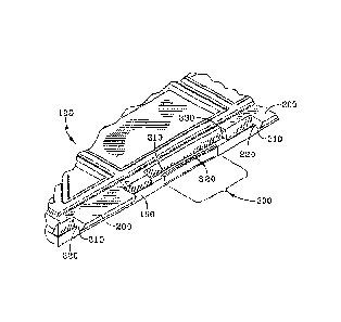
FIGS. 6 - 9 show the embodiment of the interlocks which permit the narrow
gap between the interlocked tiles. Using the same numbering conventions as the
prior
art, the tray substrate 100 is provided with upward tabs 200 and downward tabs
300.
11
CA 02765076 2017-01-19
. As shown in MG. 6, which is a view from the bottom of the tray
substrate, the
upward tab 200 includes a convex surface 210 and a valley 220. The downward
tab 300
includes a concave surface 310 and a lip 320. As the downward tab 300 is urged
against
the upward tab 200, the downward tab 300 flexes as the lip 320 slides over the
convex
surface 210 and into the valley 220, such that the lip 320 snaps into the
valley 220 and
the concave surface 310 presses over the convex surface 210.
The thin grout line is achieved by the fact that at least a portion of the
channel
310 is recessed into the wall of the tray substrate 330 and underneath the
tray surface.
Depending upon the width of grout line desired, 310, at a least a portion of
the lip, 320,
could lie directly under the vertical tray edge 160. At least a portion of at
least some of
the downward tabs of the plurality of downward tabs is underneath the tray
surface.
As in the prior art, there may also be grout members protruding from the edge
of the
tray substrate. This is shown in FIG. 10 with grout holders 270 and the gap
between
them 280.
FIGS 11A and 11B show two trays assembled and the narrow thin grout line.
FIG 11A shows two disassembled tray substrates 100 each having a horizontal
surface
110. As can be seen in the tray substrate on the left, the valley 310 of the
downward
facing tab is recessed underneath the horizontal surface of the tray
substrate. FIG 11B
shows the two tray substrates interlocked. As can be seen the upward facing
tab 200
interlocks with the downward facing tab and the lip 210 of the upward facing
is mated
to the valley 310 of the downward facing tab. Because the downward facing tab
is at
partially underneath the horizontal tray surface, the interlock produces a
narrower grout
line than the prior art.
An optional padding 500 is shown in FIG. 12. The padding 500 may be over-
molded to the tray bottom.
12
CA 02765076 2017-01-19
= As is evident from the foregoing description, certain aspects of the
present
invention are not limited by the particular details of the examples
illustrated herein, and
it is therefore contemplated that other modifications and applications, or
equivalents
thereof, will occur to those skilled in the art. It is accordingly intended
that the claims
shall cover all such modifications and applications that do not depart from
the scope of
the present invention.
13