Note : Les descriptions sont présentées dans la langue officielle dans laquelle elles ont été soumises.
CA 02765439 2012-01-23
HEAT EXCHANGER AND ASSOCIATED METHOD
EMPLOYING A STIRLING ENGINE
TECHNOLOGICAL FIELD
Embodiments of the present disclosure relate generally to heat exchangers and
associated
methods and, more particularly, to heat exchangers and associated methods that
utilize a fan to
increase the heat transfer rate.
BACKGROUND
It is desirable in many applications to provide for heat transfer, such as to
either heat or
cool a fluid or other workpiece. For example, a heat exchanger may remove
waste heat from a
mechanical or electrical system, such as an air conditioning condenser. One
form of heat
transfer is convective heat transfer. However, convective heat transfer is not
generally very
efficient. Indeed, to transfer heat, particularly a relatively large amount of
heat, from one fluid to
another, utilizing convective heat transfer, a relatively large heat transfer
surface must generally
be provided. To provide an expansive heat transfer surface, heat exchangers
have been
developed that include a plurality of coils configured to carry a primary
fluid. As such, heat is
either transferred from or to the primary fluid circulating through the heat
exchanger as a result
of heat transfer between the primary fluid and a secondary fluid that
surrounds and flows over
the heat transfer surface of the heat exchanger.
In order to increase the heat transfer rate, a heat exchanger may include a
fan that forces a
secondary fluid across the coils of the heat exchanger. While the movement of
the secondary
fluid across the coils of the heat exchanger increases the heat transfer rate,
the increase in the
heat transfer rate comes at the expense of the energy required to operate the
fan. In this regard,
the fan may be electrically actuated so as to consume electrical energy during
its operation. For
example, a fan may be driven by an electrical motor. Alternatively, the fan
may be driven by a
mechanical source so as to consume mechanical energy during its operation. For
example, the
radiator fan of some automobiles may be driven by the rotational energy
provided by the engine
drive shaft. In either instance, the fan increases the energy consumption of a
heat exchanger. As
the fan is generally configured to be activated so long as heat transfer is
required, the fan may
- 1 -
CA 02765439 2014-12-03
consume energy over a fairly long period of time, thereby correspondingly
increasing the
operating costs and the carbon footprint of the heat exchanger.
In addition, in instances in which the fan is driven by electrical energy from
an
electrical power source, electrical wires generally extend from the electrical
power source to
the fan. In some applications, the routing, placement and handling of the
electrical wiring may
prove challenging, such as in instances in which the wiring must be routed
over or along a
hinge or other moveable joint.
As such, it would be desirable to provide a heat exchanger that consumes less
energy,
such as from an external electrical or mechanical power source, and that has a
smaller carbon
footprint. It would also therefore be desirable to provide a heat exchanger
that did not require
wiring that potentially had to be routed over or along a hinge or other
moveable joint.
BRIEF SUMMARY
A heat exchanger and associated method are provided according to embodiments
of the
present disclosure that may reduce or eliminate the energy costs and carbon
footprint of a heat
exchanger. In this regard, the heat exchanger and method of one embodiment may
eliminate or
reduce the need for an external mechanical or electrical power source to drive
the fan. The
heat exchanger and method of one embodiment may also eliminate any requirement
that
electrical wiring extend from an electrical power source to the fan.
In accordance with one disclosed aspect there is provided a heat exchanger
including a
plurality of coils configured to carry a primary fluid, the plurality of coils
having an inlet for
receiving the primary fluid and an outlet through which the primary fluid
exits the plurality of
coils. The apparatus also includes a fan including a plurality of fan blades
operable to cause a
flow of a secondary fluid across the plurality of coils to facilitate heat
transfer between the
primary and secondary fluids. The apparatus further includes a Stirling engine
operably
connected to the fan and including at least one piston and first and second
regions containing a
working fluid, the Stirling engine being positioned relative to the fan such
that the first region
is outside of a flow of the secondary fluid and the second region is at least
partially within the
flow of the secondary fluid thereby providing a temperature differential
between the first and
second regions operable to cause motion of the piston and rotation of the fan
blades. The heat
- 2 -
CA 02765439 2014-12-03
transfer between the primary and secondary fluids causes a temperature
differential between
primary fluid received at the inlet and primary fluid exiting the outlet of
the plurality of coils.
The outlet extends around the second region of the Stirling engine providing
thermal
communication between the primary fluid and the working fluid for enhancing
the temperature
differential between the first and second regions of the Stirling engine.
The primary fluid at one of the inlet or the outlet may be warmer and
therefore may
include warmer primary fluid than the primary fluid at the other of the inlet
or the outlet that
may include cooler primary fluid.
The working fluid within the first region of the Stirling engine may be in
thermal
communication with the warmer primary fluid.
The first region of the Stirling engine may be at least partially immersed
within the
warmer primary fluid.
The inlet may wrap about the first region of the Stirling engine.
The plurality of coils may include a first set of coils proximate the inlet
and a second
set of coils proximate the outlet and the temperature differential between
primary fluid
received at the inlet and primary fluid exiting the outlet may cause a
temperature differential
between the first and second sets of coils, and one of the first and second
regions of the
Stirling engine may be in thermal communication with the first set of coils
and the other of the
first and second regions may be in thermal communication with the second set
of coils.
The heat exchanger may include a plurality of Stirling engines operably
connected to
the fan and configured to cooperate to cause rotation of the fan blades.
In accordance with another disclosed aspect there is provided a method for
exchanging
heat. The method involves circulating a primary fluid through a plurality of
coils, the plurality
of coils having an inlet for receiving the primary fluid and an outlet through
which the primary
fluid exits the plurality of coils. The method also involves producing a flow
of a secondary
fluid across the plurality of coils by causing rotation of a plurality of fan
blades of a fan
operably connected to a Stirling engine, the flow of secondary fluid
facilitating heat transfer
between the primary and secondary fluids. The Stirling engine includes first
and second
regions containing a working fluid and is positioned relative to the fan such
that the first
region is outside of a flow of the secondary fluid and the second region is at
least partially
- 2a -
CA 02765439 2014-12-03
within the flow of the secondary fluid for providing a temperature
differential between the first
and second regions of the Stirling engine, the temperature differential being
operable to cause
rotation of the plurality of fan blades. The heat transfer between the primary
and secondary
fluids causes a temperature differential between primary fluid received at the
inlet and primary
fluid exiting the outlet of the plurality of coils and the outlet extends
around the second region
of the Stirling engine providing thermal communication between the primary
fluid and the
working fluid for enhancing the temperature differential between the first and
second regions
of the Stirling engine.
The primary fluid at one of the inlet or the outlet may be warmer and
therefore may
involve warmer primary fluid than the primary fluid at the other of the inlet
or the outlet that
may involve cooler primary fluid.
Providing the temperature differential between the first and second regions of
the
Stirling engine may involve providing for the working fluid within the first
region of the
Stirling engine to be in thermal communication with the warmer primary fluid.
Providing for the working fluid within the first region of the Stirling engine
to be in
thermal communication with the warmer primary fluid may involve at least
partially
immersing the first region of the Stirling engine within the warmer primary
fluid.
Providing for the working fluid within the first region of the Stirling engine
to be in
thermal communication with the warmer primary fluid may involve positioning
the inlet so as
to wrap about the first region of the Stirling engine.
The plurality of coils include a first set of coils proximate the inlet and a
second set of
coils proximate the outlet and the temperature differential between primary
fluid received at
the inlet and primary fluid exiting the outlet may cause a temperature
differential between the
first and second sets of coils, and one of the first and second regions of the
Stirling engine may
be in thermal communication with the first set of coils and the other of the
first and second
regions is in thermal communication with the second set of coils.
The plurality of coils may include first and second sets of coils, and the
primary fluid
may be warmer in the first set of coils than in the second set of coils.
Providing for the
- 2b -
CA 02765439 2013-12-17
temperature differential may involve providing for the working fluid within
the first region of
the Stirling engine to be in thermal communication with the first set of
coils.
The plurality of coils may include first and second sets of coils, and the
primary fluid
may be warmer in the first set of coils than in the second set of coils.
Providing for the
temperature differential may involve providing for the working fluid within
the second region
of the Stirling engine to be in thermal communication with the second set of
coils.
A heat exchanger in accordance with another embodiment includes a plurality of
coils
configured to carry a primary fluid. The heat exchanger also includes a fan
including a
plurality of fan blades configured to force a secondary fluid across the
plurality of coils to
facilitate heat transfer between the primary and secondary fluids. The heat
exchanger of this
embodiment also includes a Stirling engine operably connected to the fan and
configured to
cause rotation of the fan blades. While the heat exchanger of one embodiment
may include a
single Stirling engine operably connected to the fan, the heat exchanger of
other embodiments
may include a plurality of Stirling engines operably connected to the fan and
configured to
cooperate to cause rotation of the fan blades.
The Stirling engine may include at least one piston and first and second
regions
containing fluid. As such, the Stirling engine of one embodiment may be
positioned relative to
the fan such that the first region of the Stirling engine is outside of the
flow of the secondary
- 2c -
CA 02765439 2012-01-23
fluid and the second region of the Stirling engine is at least partially
within the flow of the
secondary fluid, thereby creating a temperature differential between the first
and second regions.
The plurality of coils may include an inlet and an outlet through which the
primary fluid
enters and exits the plurality of coils, respectively. The primary fluid at
the inlet and the outlet
has different temperatures as a result of the heat transfer. As such, the
primary fluid at one of the
inlet or the outlet is warmer and therefore is considered warmer fluid than
the primary fluid at
the other of the inlet or the outlet that is considered cooler fluid. In one
embodiment, the fluid
within the first region of the Stirling engine is in communication with the
warmer fluid. For
example, the first region of the Stirling engine may be at least partially
disposed within the
warmer fluid. Alternatively, the inlet may extend at least partially alongside
the first region of
the Stirling engine. In addition to or instead of the fluid within the first
region of the Stirling
engine being in communication with the warmer fluid, the fluid within the
second region of the
Stirling engine may, in one embodiment, be in thermal communication with the
cooler fluid.
The plurality of coils may include first and second sets of coils with the
primary fluid
being warmer in the first set of coils than in the second set of coils. In
this embodiment, the fluid
within the first region of the Stirling engine may be in thermal communication
with the first set
of coils. Additionally or alternatively, the fluid within the second region of
the Stirling engine
may be in thermal communication with the second set of coils.
In another embodiment, a method is provided that includes circulating a
primary fluid
through a plurality of coils and providing for a temperature differential
between first and second
fluid-containing regions of the Stirling engine so as to cause rotation of a
plurality of fan blades
of a fan. The method also includes forcing a secondary fluid across the
plurality of coils as a
result of the rotation of the plurality of fan blades to facilitate heat
transfer between the primary
and secondary fluids.
In one embodiment, the circulation of the primary fluid includes permitting
the primary
fluid to enter and exit the plurality of coils through an inlet and an outlet,
respectively. The
primary fluid at the inlet and the outlet has different temperatures as a
result of the heat transfer
such that primary fluid at one of the inlet or the outlet is warmer and is
therefore considered
warmer fluid than the primary fluid at the other of the inlet or the outlet
that is considered cooler
fluid. In this embodiment, the provision of the temperature differential may
include providing
for the fluid within the first region of the Stirling engine to be in thermal
communication with the
- 3 -
CA 02765439 2012-01-23
warmer fluid. For example, the first region of the Stirling engine may be at
least partially
disposed within the warmer fluid. Alternatively, the inlet may be positioned
so as to extend at
least partially alongside the first region of the Stirling engine.
Additionally or alternatively, the
provision of the temperature differential may include providing for the fluid
within the second
region of the Stirling engine to be in thermal communication with the cooler
fluid.
The plurality of coils of one embodiment may include first and second sets of
coils with
the primary fluid being warmer in the first set of coils than in the second
set of coils. In this
embodiment, the method may provide for the temperature differential by
providing for the fluid
within the first region of the Stirling engine to be in thermal communication
with the first set of
coils. Additionally or alternatively, the method of this embodiment may
provide for the
temperature differential by providing for the fluid within the second region
of the Stirling engine
to be in thermal communication with the second set of coils. The method of one
embodiment
may also provide for the temperature differential by positioning the Stirling
engine relative to the
fan such that the first region of the Stirling engine is outside of a flow of
the secondary fluid and
the second region of the Stirling engine is at least partially within the flow
of the secondary fluid.
In accordance with embodiments of the heat exchanger and associated method,
the fan
may be driven so as to rotate the fan blades in an energy efficient and
environmentally friendly
manner. However, the features, functions and advantages that have been
discussed may be
achieved independently in various embodiments of the present disclosure and
may be combined
in yet other embodiments, further details of which may be seen with reference
to the following
descriptions and drawings.
BRIEF DESCRIPTION OF THE SEVERAL VIEWS OF THE DRAWINGS
Having thus described embodiments of the present disclosure in general terms,
reference
will now be made to the accompanying drawings, which are not necessarily drawn
to scale, and
wherein:
Figure 1 is a schematic representation of a heat exchanger in accordance with
one
embodiment of the present disclosure;
Figure 2 is a schematic representation of a two-cylinder Stirling engine;
Figure 3 is a schematic representation of a single-cylinder Stirling engine;
Figure 4 is a schematic representation of a displacer-type Stirling engine;
- 4 -
CA 02765439 2012-01-23
Figure 5 is a schematic representation of a heat exchanger in accordance with
another
embodiment of the present disclosure;
Figure 6 is a schematic representation of a heat exchanger employing a two-
cylinder
Stirling engine in accordance with one embodiment to the present disclosure;
Figure 7 is a schematic representation of a heat exchanger employing a single-
cylinder
Stirling engine in accordance with one embodiment to the present disclosure;
and
Figure 8 is a schematic representation of a heat exchanger including two
single-cylinder
Stirling engines in accordance with one embodiment to the present disclosure.
DETAILED DESCRIPTION
Embodiments of the present disclosure now will be described more fully
hereinafter with
reference to the accompanying drawings, in which some, but not all embodiments
are shown.
Indeed, these embodiments may be embodied in many different forms and should
not be
construed as limited to the embodiments set forth herein; rather, these
embodiments are provided
so that this disclosure will satisfy applicable legal requirements. Like
numbers refer to like
elements throughout.
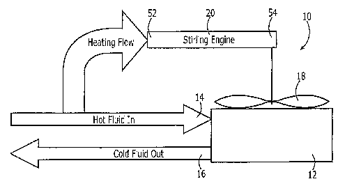
A heat exchanger 10 in accordance with one embodiment of the present
disclosure is
illustrated in Figure 1. The heat exchanger 10 may include a plurality of
coils 12 configured to
carry a primary fluid. The primary fluid that is circulated through the
plurality of coils 12 may
be any of a variety of fluids including various gas or liquids. The plurality
of coils 12 may
include an inlet 14 through which the primary fluid enters and an outlet 16
through which the
primary fluid exits. During the flow of the primary fluid through the
plurality of coils 12, heat
may be transferred to or from the primary fluid depending upon the
application. For example,
the heat exchanger 10 may be employed in an application in which the primary
fluid is to be
cooled. As such, relatively hot fluid may enter the plurality of coils 12
through the inlet 14 and
be cooled during its traversal through the plurality of coils such that a
cooler fluid exits at the
outlet 16. Alternatively, the heat exchanger 10 may be configured to heat a
primary fluid. In an
embodiment in which the primary fluid is heated, a cooler fluid may enter the
plurality of coils
12 through the inlet 14 and be heated during its traversal through the
plurality of coils such that a
warmer fluid exits the plurality of coils at the outlet 16.
- 5 -
CA 02765439 2012-01-23
In order to improve the heat transfer with the primary fluid, the heat
exchanger 10 may
include a fan 18 having a plurality of fan blades configured for rotation so
as to force a
secondary fluid across the plurality of coils 12. As with the primary fluid,
the secondary fluid
may be any type of fluid including various gases or liquids. As a result of a
temperature
differential between the primary and secondary fluids, heat transfer may occur
between the
primary and secondary fluids. In the embodiment of Figure 1 in which the
primary fluid is to be
cooled within the plurality of coils 12, for example, the secondary fluid that
is forced across the
plurality of coils may be cooler than the primary fluid that is circulating
through the plurality of
coils or at least cooler than the primary fluid that enters the plurality of
coils through the inlet 14.
In this embodiment, heat would transfer from the primary fluid as it
propagates through the
plurality of coils 12 to the secondary fluid, thereby cooling the primary
fluid and warming the
secondary fluid. Conversely, in an embodiment in which the primary fluid is to
be heated during
its propagation through the plurality of coils 12, the secondary fluid may be
warmer than the
primary fluid or, at least, warmer than the primary fluid that enters the
plurality of coils through
the inlet 14. In this embodiment, heat would transfer from the secondary fluid
to the primary
fluid, thereby cooling the secondary fluid and warming the primary fluid.
As shown in Figure 1, the heat exchanger 10 also includes a Stirling engine 20
that is
operably connected to the fan 18 and is configured to cause rotation of the
fan blades. By
driving the fan 18 with a Stirling engine 20, the dependence of the fan on
other electrical or
mechanical power for operation may be reduced or eliminated, thereby
conserving energy and
reducing the carbon footprint of the heat exchanger 10. In instances in which
the fan 18 is driven
exclusively by the Stirling engine 20, the fan no longer need be connected to
an electrical power
source by wires, thereby simplifying the wiring design of the platform.
A Stirling engine 20 operates on a temperature differential between a heat
source and a
cold sink and may provide an output in the form of a rotating power shaft. A
Stirling engine 20
may be described as a closed cycle externally heated heat engine in which the
working fluid is
not renewed for every cycle. A Stirling engine 20 may include a variety of
working fluids
including air, hydrogen, helium, nitrogen, etc. Since the working fluid is in
a closed loop with
no exhaust, the theoretical efficiency of a Stirling-cycle heat engine 20 may
approach that of a
Carnot-cycle heat engine which has the highest thermal efficiency attainable
by any heat engine.
- 6 -
CA 02765439 2012-01-23
A Stirling engine 20 may operate over any wide range of temperature
differentials including very
low temperature differentials.
There are various types of Stirling engines 20. For example, a two-cylinder
Stirling
engine 20 is illustrated in Figure 2. In this configuration, two cylinders are
employed to produce
work, such as the rotation of a power shaft. During operation, one cylinder
may be heated by
exposure to an external heat source, while the other cylinder may be cooled by
exposure to an
external heat sink. The working fluid may be transferred between the two
cylinders with the
fluid expanding upon exposure to heat and being compressed when cooled. The
alternate
expansion and compression of the working fluid drives the two pistons 22, one
of which is
positioned within each cylinder of the Stirling engine 20. The pistons 22, in
turn, may drive a
rotating power shaft.
A Stirling engine 20 has four phases of operation, namely, expansion,
transfer,
contraction and transfer. In expansion, most of the working fluid has been
driven into the hot
cylinder 24. In the hot cylinder, the working fluid is heated and expands,
both within the hot
cylinder 24 and through propagation into the cold cylinder 26, thereby driving
both pistons 22
inward. The movement of both pistons 22 inward may rotate the crankshaft 28 by
about 90
degrees. Following expansion of the working fluid and rotation of the
crankshaft 28 by about 90
degrees, the majority of the working fluid, such as about two-thirds of the
working fluid, may
still be located in the hot cylinder 24. However, flywheel momentum may cause
the crankshaft
28 to continue to rotate for about another 90 degrees, thereby causing the
majority of the
working fluid to be transferred to the cold cylinder 26. In the cold cylinder
26, the working fluid
is cooled and contracts, thereby drawing both pistons 22 outward and causing
the crankshaft 28
to rotate another 90 degrees. With the contracted gas still located in the
cold cylinder 26,
flywheel momentum may again cause the crankshaft 28 to continue to rotate by
about another 90
degrees, thereby transferring the working fluid back to the hot cylinder 24 to
complete the cycle.
As will be apparent from the foregoing discussion, the designations of the
cylinders as hot and
cold are relative terms and employed to indicate that the working fluid is
heated within the hot
cylinder 24 and cooled within the cold cylinder 26.
An alternative type of Stirling engine 20 is a single cylinder Stirling engine
that has four
phases of operation, namely, expansion, transfer, contraction and transfer. As
shown in Figure 3,
a single cylinder Stirling engine 20 may include a single piston 30 connected
to a crankshaft 32.
- 7 -
CA 02765439 2012-01-23
The single cylinder has opposed hot and cold ends 34, 36 with the working
fluid being heated in
the hot end and the working fluid being cooled in the cold end. In expansion,
the majority of the
working fluid is disposed at the hot end 34 of the cylinder. While in the hot
end 34 of the
cylinder, the working fluid is heated and expands, driving the piston 30
outward, e.g., to the right
in the embodiment illustrated in Figure 3, and causing the crankshaft 32 to
rotate about 90
degrees. Following expansion of the working fluid, the majority of the working
fluid is still
located at the hot end 34 of the cylinder. However, flywheel momentum may
cause the
crankshaft 32 to continue to rotate about another 90 degrees. This further
rotation of the
crankshaft 32 will cause the majority of the gas to move around the displacer
38 from the hot end
34 to the cool end 36 of the single cylinder. At the cool end 36, the working
fluid is cooled and
contracts, thereby drawing the piston 30 inward, which causes the crankshaft
32 to rotate through
about another 90 degrees. At this stage, the contracted working fluid is still
located near the cool
end 36 of the cylinder. However, flywheel momentum may again continue to
rotate the
crankshaft 32 about another 90 degrees, thereby moving the displacer 38 and
returning the
majority of the working fluid to the hot end 34 of the cylinder.
As shown in Figure 4, another type of Stirling engine 20 is a displacer
Stirling engine.
The operation of a displacer Stirling engine 20 is similar to a single
cylinder Stirling engine with
the exception that the heat transfer surfaces for both the hot and cold sides
40, 42 of the displacer
44 are expanded to capture and eject heat more efficiently. This increase in
the heat transfer rate
enables a displacer-type Stirling engine 20 to operate between heat sources
and heat sinks that
have a relatively low temperature differential. In further contrast to a
single cylinder Stirling
engine, the drive piston 46 for a displacer-type Stirling engine may be
external to the chamber 48
that contains the working fluid.
Regardless of the type of Stirling engine 20, the Stirling engine may include
first and
second regions 52, 54 containing fluid. As described above, in conjunction
with the Stirling
engines 20 of Figures 2-4, a temperature differential may be created between
the first and second
fluid-containing regions 52, 54 of the Stirling engine. For example, the first
fluid-containing
region 52 may be heated and/or the second fluid-containing region 54 may be
cooled. As a result
of this temperature differential, the Stirling engine 20 may drive a rotating
drive shaft that, in
turn, is operably connected to the fan 18 so as to cause rotation of the fan
blades and the forced
circulation of the secondary fluid through the plurality of coils 12.
- 8 -
CA 02765439 2012-01-23
The temperature differential between the first and second fluid-containing
regions 52, 54
of the Stirling engine 20 may be created in a variety of different manners.
For example, the
temperature differential may be created by utilizing the temperature
differential between the
primary fluid that enters and exits the plurality of coils 12. In this regard,
as a result of the heat
transfer that occurs during propagation of the primary fluid through the
plurality of coils 12, the
primary fluid at the inlet 14 of the plurality of coils has a different
temperature than the primary
fluid at the outlet 16 of the plurality of coils. Thus, the primary fluid at
one of the inlet 14 or the
outlet 16 is warmer and therefore is considered warmer fluid than the primary
fluid at the other
of the inlet or outlet that is considered a cooler fluid. In the embodiment
illustrated in Figure 1 in
which the primary fluid is cooled during its circulation through the plurality
of coils 12, the
primary fluid at the inlet 14 is the warmer fluid, and the primary fluid at
the outlet 16 is the
cooler fluid. However, in an alternative embodiment in which the primary fluid
is heated during
its circulation through the plurality of coils 12, the primary fluid at the
outlet 16 would be the
warmer fluid, and the primary fluid at the inlet 14 would be the cooler fluid.
As shown schematically in Figure 1 by the heating flow arrow, the fluid within
the first
region 52 of the Stirling engine 20 of one embodiment may be in thermal
communication with
the warmer fluid. As a result of heat transfer from the warmer fluid to the
fluid within the first
region 52 of the Stirling engine 20, the fluid within the first region of the
Stirling engine would
be warmer than the fluid within the second region 54 of the Stirling engine,
thereby establishing
a temperature differential therebetween. The first region 52 of the Stirling
engine 20 may be
placed in thermal communication with the warmer fluid in various manners. For
example, the
first region 52 of the Stirling engine 20 may be at least partially disposed,
such as by being
immersed, within the warmer fluid. Alternatively, the inlet 14 may be
positioned so as to extend
at least partially alongside the first region 52 of the Stirling engine 20.
For example, the inlet 14
could wrap about the first region 52 of the Stirling engine 20 one or more
times.
In order to establish the temperature differential between the first and
second fluid-
containing regions 52, 54 of the Stirling engine 20, the second region of the
Stirling engine can
be disposed in thermal communication with the cooler fluid, such as the
primary fluid at the
outlet of the plurality of coils 12 in the embodiment schematically
illustrated in Figure 5 by the
cooling flow arrow. The positioning of the second fluid-containing region 54
of the Stirling
engine 20 in thermal communication with the cooler fluid may be in addition to
or instead of the
- 9 -
CA 02765439 2012-01-23
positioning of the first fluid-containing region 52 of the Stirling engine in
thermal
communication with the warmer fluid. For example, the heat exchanger 10 of the
embodiment
of Figure 5 schematically illustrates each of the first and second regions 52,
54 of the Stirling
engine 20 being in thermal communication with the warmer fluid and the cooler
fluid,
respectively. The second fluid-containing region 54 of the Stirling engine 20
may be placed in
thermal communication with the cooler fluid in various manners including, for
example, by at
least partially disposing, such as by at least partially immersing, the second
fluid-containing
region of the Stirling engine within the cooler fluid, such as at the outlet
16 of the plurality of
coils 12 in the embodiment of Figure 5. Alternatively, in the embodiment of
Figure 5 in which
the primary fluid is cooled during its traversal through the plurality of
coils 12, the outlet 16 may
be positioned so as to extend at least partially alongside the second fluid-
containing region 54 of
the Stirling engine 20, such as extending the outlet around the second fluid-
containing region of
the Stirling engine one or more times.
The plurality of coils 12 may include first and second sets of coils with the
primary fluid
being warmer in the first set of coils than in the second set of coils. In
this regard, the coils that
are proximate to, or closest to, the inlet 14 in terms of the flow of the
primary fluid may be the
first set of coils in an embodiment in which the heat exchanger 10 is utilized
to cool the primary
fluid. In this embodiment, the coils that are proximate to or closest to the
outlet 16 in terms of
the flow of the primary fluid may therefore be the second set of coils. In
order to establish the
temperature differential between the first and second fluid-containing regions
52, 54 of the
Stirling engine 20, the fluid within the first region of the Stirling engine
may be in thermal
communication with the first set of coils in which the primary fluid is
warmer. As such, the
warmer fluid within the first set of coils may warm the fluid within the first
region 52 of the
Stirling engine 20 and create the temperature differential for causing
operation of the Stirling
engine. Additionally or alternatively, the fluid within the second region 54
of the Stirling engine
20 may be in thermal communication with the second set of coils having a
cooler fluid therein
such that the fluid within the second region of the Stirling engine is
correspondingly cooled. By
cooling the fluid within the second region 54 of the Stirling engine 20, the
temperature
differential may be created or enhanced, thereby causing operation of the
Stirling engine.
The first and second regions 52, 54 of the Stirling engine 20 may be
positioned in thermal
communication with the first and second sets of coils, respectively, in
various manners. For
-10-
CA 02765439 2012-01-23
example, the first region 52 of the Stirling engine 20 may be positioned
proximate to and in
thermal communication with the first set of coils, while the second region 54
of the Stirling
engine may be positioned proximate to and in thermal communication with the
second set of
coils. An example of a heat exchanger 10 in which the first and second regions
52, 54 of the
Stirling engine 20 are in thermal communication with the first and second sets
of coils,
respectively, is shown in Figure 6. In the embodiment of Figure 6, the heat
exchanger 10 is
configured to cool the primary fluid such that warmer fluid enters the
plurality of coils 12
through the inlet 14, and cooler fluid exits the plurality of coils through
the outlet 16. As such, in
the orientation of Figure 6, the upper half of the plurality of coils 12 may
be the first set of coils
in which warmer fluid propagates, while the lower half of the plurality of
coils may be the
second set of coils through which a cooler fluid propagates as a result of the
transfer of heat
away from the primary fluid to the secondary fluid as the primary fluid
propagates through the
plurality of coils. As such, the first fluid-containing region 52 of the
Stirling engine 20 of Figure
6 is positioned proximate to, such as in physical contact and thermal
communication with, the
first set of coils, while the second fluid-containing region 54 of the
Stirling engine is positioned
proximate to and in thermal communication with the second set of coils. In the
illustrated
embodiment, the second fluid-containing region 54 includes a plurality of fins
55 that increase
the heat transfer surface and, therefore, the cooling of the fluid within the
second fluid-
containing region of the Stirling engine 20. However, other embodiments of the
Stirling engine
20 need not include fins 55 proximate the second region 54.
In order to create temperature differential between the first and second fluid-
containing
regions 52, 54 of the Stirling engine 20, the Stirling engine may be
positioned relative to the fan
18 such that the first region, or at least a portion of the first region, of
the Stirling engine is
outside of a flow of the secondary fluid, that is, the flow of the secondary
fluid created by the
rotation of the fan blades. In contrast, the second region 54 of the Stirling
engine 20 is at least
partially within the flow of the secondary fluid. As shown in Figure 6, for
example, the second
fluid-containing region 54 is disposed within the flow of the secondary fluid,
while the first
fluid-containing region 52 is outside of the flow of the secondary fluid. As
such, the flow of the
secondary fluid over the second fluid-containing region 54 of the Stirling
engine 20 will also
cool the fluid within the second region of the Stirling engine relative to the
fluid within the first
region 52 of the Stirling engine, thereby further creating or enhancing the
temperature
- 11 -
CA 02765439 2012-01-23
differential between the first and second fluid-containing regions that causes
operation of the
Stirling engine.
Another embodiment of a heat exchanger 10 in accordance with an embodiment of
the
present disclosure in which the Stirling engine 20 has a single cylinder as
shown in Figure 7. As
shown, the first fluid-containing region 52 of the single cylinder Stirling
engine 20 is positioned
in thermal communication with the first set of coils as a result of its
position proximate the inlet
14 through which warmer fluid enters the plurality of coils 12 in this
embodiment. Additionally,
the first region 52 of the Stirling engine 20 is positioned outside of the
flow of the secondary
fluid created by the rotation of the fan blades. Conversely, the second fluid-
containing region 54
of the single cylinder Stirling engine 20 is positioned at least partially
within the flow of the
secondary fluid so that the fluid within the second region of the Stirling
engine is cooled in order
to further create the temperature differential between the first and second
regions of the Stirling
engine.
Although the heat exchanger 10 may include a single Stirling engine 20, the
heat
exchanger of at least some embodiments may include a plurality of Stirling
engines operably
connected to the fan 18 and configured to cooperate to cause a rotation of the
fan blades. As
shown in Figure 8, for example, a heat exchanger 10 that includes two single
cylinder Stirling
engines 20 that are positioned in such a manner as to cooperate with one
another to cause
rotation of the fan blades is depicted. As described above in conjunction with
the embodiment of
Figure 7, each of the single cylinder Stirling engines 20 is positioned
relative to the plurality of
coils 12 such that the respective first regions 52 of the Stirling engines are
positioned outside of
the flow of the secondary fluid, while the respective second regions 54 of the
Stirling engines are
positioned within the flow of the secondary fluid so as to create the
temperature differential
between the fluids within the first and second regions of the Stirling
engines.
Many modifications and other embodiments of the present disclosure set forth
herein will
come to mind to one skilled in the art to which these embodiments pertain
having the benefit of
the teachings presented in the foregoing descriptions and the associated
drawings. Therefore, it
is to be understood that the present disclosure is not to be limited to the
specific embodiments
disclosed and that modifications and other embodiments are intended to be
included within the
scope of the appended claims. Although specific terms are employed herein,
they are used in a
generic and descriptive sense only and not for purposes of limitation.
- 12 -