Note : Les descriptions sont présentées dans la langue officielle dans laquelle elles ont été soumises.
CA 02765630 2015-08-28
SOLID DRUG TABLETS FOR IMPLANTABLE DRUG DELIVERY DEVICES
Background
This disclosure is generally in the field of controlled drug delivery, and
more
particularly in the field of implantable medical devices for controlled drug
release and drug
formulations for use with implantable medical devices.
A variety of devices and methods have been developed to deliver drug locally
or
regionally to mitigate problems associated with systemic drug delivery. Local
delivery of
drug to some tissue sites could be improved, however, particularly with
respect to extended
drug delivery from devices that are less invasive and uncomfortable for the
patient.
Some treatments could be improved by implanting a drug delivery device in a
body
lumen or cavity such as the bladder. For example, interstitial cystitis (IC),
painful bladder
syndrome (PBS), and chronic prostatitis/cluonic pelvic pain syndrome (CP/CPPS)
are chronic
painful disorders that are often treated by delivering a lidocaine solution to
the bladder via
instillation, but the frequent instillations required for sustained relief
entail inconvenience,
discomfort, and the risk of infection associated with urinary catheterization.
Similarly, the
symptoms of neurogenic bladder may be treated by delivering drugs to the
bladder via
intermittent catheterization, which carries the drawbacks described above,
among others.
These and other therapeutic or prophylactic treatments, including those for
acute post-
operative pain, could benefit from drug delivery devices for implantation in
the bladder,
particularly where local or regional drug delivery is sought, such as when the
side effects of
systemic drug delivery are intolerable or when bioavailability from oral
administration is too
low.
Implantable drug delivery devices for the bladder are known but suffer from
one or
more deficiencies. Some such known devices are loaded with a drug solution,
which are
capable only of carrying and releasing a relatively smaller amount of drug
than what could be
delivered in a less voluminous form, such as without a solvent or carrying
fluid for the drug.
An example is the UROS infuser device by Situs Corporation, as disclosed in
U.S. Patents
No. 6,171,298, No. 6,183,461, and No. 6,139,535, which can deliver
pharmaceutical
solutions of, for example, oxybutynin for the treatment of overactive bladder
or mitomycin C
1
CA 02765630 2011-12-15
WO 2010/151896
PCT/US2010/040255
for the treatment of bladder cancer. It would be desirable to provide drug
delivery systems
and devices that provide higher ratios of drug volume : device volume.
Conventional solid dosage forms are primarily designed for oral administration
and
systemic delivery, not local delivery to the bladder. Solid drug forms may not
be suited for
loading into implantable devices, particularly tiny devices of millimeter or
micrometer scales,
such as in a manner that is consistent and repeatable. Furthermore, these
solid dosage forms
are not designed to be sterilized or to be provided in sterile packaging.
Accordingly, a need exists for an improved implantable drug delivery device,
for
example, that is sufficiently small to reduce discomfort and pain associated
with deployment
and retention, that can reduce the number of surgical or interventional
procedures required for
implantation and delivery of drug over the treatment period, that can provide
controlled
delivery over an extended period, that can carry an effective amount of drug
for the extended
period in a sufficiently small payload volume, and that can be retained in the
bladder or other
vesicle or lumen without excretion or elimination until the drug payload is at
least
substantially released, even when the drug is delivered over a period of days
or weeks.
Summary
In one aspect, drug tablets suitable for use in implantable medical devices
are
provided. The solid tablet may be a compressed tablet. In a preferred
embodiment, the tablet
is a mini-tablet. In some cases, each drug tablet may have a cylindrical side
face having a
length from about 1.5 mm to about 4.7 mm and flat end faces, each end face
having a
diameter from about 1.0 mm to 3.3 mm.
In a particular embodiment, the drug tablet includes a local anesthetic agent.
For
example, the local anesthetic agent may be selected from the group consisting
of
aminoamides, aminoesters, and combinations thereof. In one case, the drug
tablet is in the
form of a solid tablet which is greater than 50% by weight the local
anesthetic agent. The
local anesthetic agent may be selected from the group consisting of lidocaine,
prilocaine,
mepivacaine, bupivacaine, articaine, ropivacaine, and combinations thereof The
drug tablet
may be between 70 wt% and 99 wt% the local anesthetic agent. The drug tablet
may be
made by granulating the local anesthetic agent into granules and then
compressing the
granules into the solid tablet form.
The solid tablet may further include one or more excipients, such as a water
soluble
excipient. The excipient may include a binder. The binder may be selected from
the group
consisting of polyvinylpyrrolidone, poly(ethylene glycol), poly(ethylene
oxide), poloxamers,
and combinations thereof. For example, the binder may include
polyvinylpyrrolidone. The
2
CA 02765630 2015-08-28
excipient may include a lubricant. The lubricant may be selected from the
group consisting of
leucine, sodium lauryl sulfate, sucrose stearate, boric acid, sodium acetate,
sodium oleate,
sodium stearyl fumarate, poly(ethylene glycol), and combinations thereof. For
example, the
lubricant may include PEG 8000. In some embodiments, the solid tablet may
include a
lubricant and a binder. For example, the lubricant may include between about
5.5 wt% and
about 8.5 wt% of the solid tablet, and the binder may include between about 1
wt% and about
5 wt% of the solid tablet. In some embodiments, the lubricant may include PEG
8000 and the
binder may include polyvinylpyrrolidone.
The drug tablet may include one or more water soluble excipients, which are
from 2
wt% to 25 wt% of the solid tablet. In some embodiments, the drug tablet may
include from
about 3 mg to about 40 mg of a lidocaine base. In other embodiments, the drug
tablet may
include from about 3 mg to about 40 mg of a water soluble salt of lidocaine.
Therefore, a particular embodiment relates to a drug tablet comprising:
a local anesthetic agent which is an aminoamide, an aminoester, or a
combination thereof,
wherein the drug tablet is in the form of a solid tablet that comprises the
local
anesthetic agent in an amount greater than 75% by weight of the solid tablet,
wherein the solid tablet is in the form of a mini-tablet.
In another aspect, an implantable drug delivery device includes one or more of
drug
tablets and a biocompatible housing containing the one or more drug tablets.
The device may
be sized and shaped for intravesical insertion. The device may further include
a retention
frame operably connected to the housing. In some embodiments of such a device,
the housing
may be sized, shaped, and constructed for intravesical insertion. The housing
may include at
least one orifice through which the drug from the dosage form, which becomes
solubilized in
vivo, is released by osmotic pressure, diffusion, or a combination thereof.
The device may
have from 10 to 100 of the mini-tablets aligned in the housing. The device may
further
include a retention frame operably connected to the housing.
Therefore, another embodiment relates to an implantable drug delivery device
comprising:
at least one drug tablet which comprises an anesthetic agent which is an
aminoamide, an aminoester, or a combination thereof, wherein the drug tablet
is in the form of
a solid tablet that comprises the anesthetic agent in an amount of 75% by
weight or more of
the solid tablet; and
a biocompatible housing containing the one or more drug tablets.
3
CA 02765630 2015-08-28
In still another aspect, a method is provided for making a solid drug tablet.
The
method may include (i) combining a drug in particulate form with at least one
water soluble
excipient to form a composition; and (ii) compressing the composition to form
a solid drug
tablet.
Another particular embodiment relates to a method of making a solid drug
tablet
comprising:
combining a drug in particulate form with at least one excipient to form a
composition; and
tableting the composition to form a solid drug tablet,
wherein the drug comprises more than 75% by weight of the solid drug tablet
and comprises a local anesthetic agent which is an aminoamide, an aminoester,
or a
combination thereof, and the at least one excipient comprises less than 25% by
weight
of the solid drug tablet.
Another particular embodiment relates to a drug dosage form comprising:
tableted particulates of a drug,
wherein the tableted particulates are in the form of a mini-tablet, the mini-
tablet
comprising the drug in an amount that is greater than 70% by weight of the
mini-tablet, with
the balance being at least one excipient.
In embodiments of the drug dosage form, the drug and the at least one
excipient are
water soluble. The drug dosage form may be from 85 wt% to 95 wt% the drug. The
mini-
tablets may each be substantially cylindrical with flat end faces.
A further embodiment relates to an implantable drug delivery device
comprising:
one or more mini-tablets as defined herein; and
a flexible and water permeable housing containing the one or more mini-
tablets,
wherein the housing is sized, shaped, and constructed for intravesical
insertion.
Brief Description of the Drawings
FIG. 1 is a plan view of an embodiment of a drug delivery device.
3a
CA 02765630 2011-12-15
WO 2010/151896
PCT/US2010/040255
FIG. 2 is a plan view of the drug delivery device shown in FIG. 1,
illustrating the
drug delivery device inside a deployment instrument.
FIG. 3 is a plan view of another embodiment of a drug delivery device.
FIG. 4 is a plan view of the drug delivery device shown in FIG. 3,
illustrating the
drug delivery device inside a deployment instrument.
FIG. 5 illustrates cross-sectional views of a device body of the drug delivery
device
shown in FIG. 3, with FIGS. 5A and 5B illustrating various placements of an
aperture.
FIG. 6 is a perspective view of an embodiment of a solid drug tablet for
implantation
or intravesical insertion.
FIG. 7 is an illustration showing the size of an example drug delivery device
in
comparison to an approximation of the bladder trigone region.
FIG. 8 illustrates an embodiment of a drug reservoir portion, wherein FIG. 8A
is a
plan view and FIG. 8B is a side cross-sectional view.
FIG. 9 illustrates example shapes for a retention frame of a drug delivery
device.
FIG. 10 illustrates example configurations for drug delivery devices having at
least
one drug delivery portion and a retention frame portion.
FIG. 11 is a block diagram illustrating an embodiment of a method of making a
solid
drug tablet.
FIG. 12 is a block diagram illustrating an embodiment of a method of making a
drug
delivery device.
FIG. 13 is a block diagram illustrating an embodiment of a method of loading a
drug
delivery device with drug units.
FIG. 14 is a side view of an embodiment of a system for loading a drug
delivery
device with drug tablets.
FIG. 15 is a schematic of another embodiment of a system for loading a drug
delivery
device with drug units.
FIG. 16 is a perspective view of another embodiment of a system for loading a
drug
delivery device with drug units.
FIG. 17 is a cross-sectional view of the embodiment of the system for loading
a drug
delivery device shown in FIG. 16.
FIG. 18 illustrates a method of implanting a drug delivery device.
FIG. 19 is a sagittal view of a male patient, illustrating a drug delivery
device exiting
a deployment instrument into a bladder of the patient.
4
CA 02765630 2015-08-28
Detailed Description
Implantable devices are provided that can be deployed, or implanted, into a
lumen or
body cavity of a patient, such as the bladder or another genitourinary site,
for release of one or
more drugs over an extended period. Drug forms for use with such devices are
also disclosed,
along with systems and methods of making such drug forms and systems and
methods of
loading such drug forms into the implantable devices. The devices, methods,
and drug forms
described herein improve upon those described in U.S. Publication No.
2009/0149833,
published June 11, 2009.
The implantable device is designed for deployment into and retention within a
portion
of the body, such as the bladder. The device may be flexible so that the
device can be
deformed for insertion, yet once implanted the device may resist excretion in
response to the
forces of urination or other forces. In particular embodiments, an implantable
drug delivery
device is loaded with one or more drugs in the form of a number of solid drug
units, such as
tablets or pellets. Using solid drug formulations permits (i) reducing the
size of an
implantable device that delivers a selected payload (e.g., mass of drug) or
(ii) increasing the
payload that may be delivered from a device of a selected size, or (iii) a
combination thereof.
Advantageously, the drug loaded device in a preferred embodiment is flexible
or
deformable despite being loaded with solid drug, as each drug unit may be
permitted to move
with reference to adjacent drug units. In particular, interstices or breaks
between the
individual drug units may form reliefs that permit deformation of the device,
while allowing
the individual drug units to retain their solid form. In one embodiment, the
solid drug is
loaded in the drug delivery device by positioning one or more drug units near
an entry into the
drug delivery device and driving the drug units into the drug delivery device
using a
pressurized gas source, such as by depressing a syringe of air in fluid
communication with the
device. For example, the drugs may be serially aligned in the narrow,
elongated lumen of a
drug reservoir.
In particular embodiments, the drug delivery device is small, such as small
enough to
be inserted through a deployment instrument extending through the urethra into
the bladder.
Such a device may be loaded with solid drug tablets that are "mini-tablets" of
reduced size. In
a preferred embodiment, the drug tablets are substantially smaller than
conventional drug
tablets, and unlike conventional tablets that tend to be squat in shape, the
drug tablets may be
tall and elongated and/or may have flat, rather than convex, end faces. The
drug tablets also
may constitute mostly drug and little or no excipients, so that the drug
tablets contain a large
amount of drug considering the tablet size. The drug delivery device may
control release of
5
CA 02765630 2011-12-15
WO 2010/151896
PCT/US2010/040255
the drug into the body, and therefore the drug tablet may include little or no
excipients that
control drug release. Instead, the excipients present in the drug tablets may
be present
primarily or completely to facilitate the tableting process. Thus, the device
may provide a
very high drug payload on a volume or weight basis, such as at least 50 wt%
drug, in contrast
to known intravesical devices, such as sponges or reticulated foam structures
that may be
loaded with as little as 1 to 10 wt% drug.
In particular embodiments, the drug delivery device may deliver lidocaine or
another
cocaine analogue locally to the bladder over a relatively extended time period
for the
treatment of a condition such as IC/PBS, neurogenic bladder, or pain such as
post-operative
pain. In such embodiments, the device may be loaded with lidocaine in solid
form, such as in
the form of a number of discrete drug tablets. Compositions of such solid drug
tablets are
provided, along with methods of making the same.
The device may be implanted non-surgically and may deliver drug long after the
implantation procedure has ended, both passively and locally. When implanted
in the
bladder, the device overcomes many deficiencies of conventional treatments,
such as delivery
via instillation, which must be repeated; delivery via conventional devices,
which must be re-
filled once implanted; delivery via catheters, which provide a path for
bacteria to migrate into
the bladder, and systemic delivery, with its associated risk of side effects
and reduced drug
delivery to the target site. On the contrary, the present device can be
implanted once and can
release drug over an extended period without surgery or frequent
interventions, reducing the
opportunity for infection and side effects, increasing the amount of drug
delivered locally or
regionally to the bladder, and improving the quality of life of the patient
during the treatment
process.
I. The Implantable Drug Delivery Device
The drug delivery device generally includes two primary parts or portions: the
drug
reservoir portion and the retention frame portion. The drug reservoir portion
may hold the
drug to be delivered into the body, and the retention frame portion may
facilitate retaining the
device in the body.
One example embodiment of a drug delivery device 100 is illustrated in FIG. 1.
The
device 100 includes a drug reservoir portion 102 and a retention frame portion
104. The drug
reservoir portion 102 is attached to discrete points on the retention frame
portion 104 but is
otherwise separate or spaced apart from the retention frame portion 104. In
FIG. 1, the
device 100 is shown in a relatively expanded shape suited for retention in the
body, and in
FIG. 2 the device 100 is shown in a relatively lower-profile shape for
deployment through
6
CA 02765630 2011-12-15
WO 2010/151896
PCT/US2010/040255
the channel 200 of a deployment instrument, such as a cystoscope or other
catheter.
Following deployment into the body, the device 100 may assume the relatively
expanded
shape to retain the drug delivery device in the body cavity or lumen.
For the purposes of this disclosure, the term "relatively higher-profile
shape" or
.. "retention shape" generally denotes any shape suited for retaining the
device in the intended
implantation location, including but not limited to the pretzel shape shown in
FIG. 1 that is
suited for retaining the device in the bladder. Similarly, the term
"relatively lower-profile
shape" or "deployment shape" generally denotes any shape suited for deploying
the drug
delivery device into the body, including the linear or elongated shape shown
in FIG. 2 that is
.. suited for deploying the device through the working channel of catheter,
cystoscope, or other
deployment instrument positioned in a lumen of the body, such as the urethra.
In one
embodiment, the drug delivery device naturally assumes the relatively expanded
shape, in
which case the device may be deformed, either manually or with the aid of an
external
apparatus, into the relatively lower-profile shape for insertion into the
body, and once
.. deployed the device may spontaneously or naturally return to the initial,
relatively expanded
shape for retention in the body.
In particular, the retention frame portion may include a retention frame that
retains the
device in the body, such as in the bladder. The retention frame may have a
certain elastic
limit and modulus that allows the device to be introduced into the body in a
relatively lower-
.. profile shape but then permits the device to return the relatively expanded
shape once inside
the body. The device may also have a sufficient elastic modulus to impede the
device from
assuming the relatively lower-profile shape once implanted, so as to limit or
prevent
accidentally expulsion of the device from the body under expected forces. For
example, the
characteristics of the retention frame may be selected to facilitate retaining
the device in the
.. relatively expanded shape despite expected forces in the bladder, such as
the hydrodynamic
forces associated with urination or contraction of the detrusor muscle. Thus,
expulsion from
the bladder is impeded or prevented so that the device can deliver a drug into
the bladder over
an extended time period. Such a configuration facilitates delivering a drug
such as lidocaine
to the bladder over an extending period for the treatment of conditions such
as interstitial
.. cystitis, neurogenic bladder, or pain, among others.
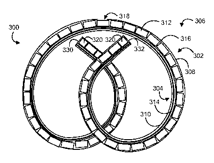
FIG. 3 illustrates another example embodiment of a drug delivery device 300
that has
a drug reservoir portion 302 and a retention frame portion 304, and FIG. 4
illustrates the
device 300 in a working channel 402 of a deployment instrument 400. The drug
reservoir
7
CA 02765630 2011-12-15
WO 2010/151896
PCT/US2010/040255
and retention frame portions 302, 304 of the drug delivery device 300 are
longitudinally
aligned and are coupled to each other along their length.
In particular, the drug delivery device 300 includes an elastic or flexible
device body
306 that defines a drug reservoir lumen 308 and a retention frame lumen 310.
The drug
reservoir lumen 308 is designed to house a drug formulation, such as a number
of solid drug
tablets 312, to form the drug reservoir portion 302. The retention frame lumen
310 is
designed to house a retention frame 314 to form the retention frame portion
304. The
illustrated lumens 308, 310 are discrete from each other, although other
configurations are
possible.
As shown in the cross-sectional views of FIG. 5, the device body 306 includes
a tube
or wall 322 that defines the drug reservoir lumen 308 and a tube or wall 324
that defines the
retention frame lumen 310. The tubes 322, 324 and lumens 308, 310 can be
substantially
cylindrical, with the drug reservoir lumen 308 having a relatively larger
diameter than the
retention frame lumen 310, although other configurations can be selected based
on, for
example, the amount of drug to be delivered, the diameter of the retention
frame, and
deployment considerations such as the inner diameter of the deployment
instrument. The
device body 306 may be formed integrally, such as via molding or extrusion,
although
separate construction and assembly of the tubes 322, 324 is possible. The wall
324 that
defines the retention frame lumen 310 may extend along the entire length of
the wall 322 that
defines drug reservoir lumen 308, so that the retention frame lumen 310 has
the same length
as the drug reservoir lumen 308 as shown, although one wall may be shorter
than the other
wall in other embodiments. Further, the two walls 322, 324 are attached along
the entire
length of the device in the illustrated embodiment, although intermittent
attachment can be
employed.
As shown in FIG. 3, the drug reservoir lumen 308 is loaded with a number of
drug
units 312 in a serial arrangement. For example, between about 10 and about 100
drug units
312 may be loaded, such as between about 30 and about 70 drug units 312, or
more
particularly between about 50 and 60 drug units 312. However, any number of
drug units
may be used. The drug reservoir lumen 308 includes an entry 330 and an exit
332, which are
shown as relatively circular openings at opposite ends of the drug reservoir
lumen 308. The
entry 330 provides ingress for the drug units 312 to be placed into the drug
reservoir lumen
308 during device loading and assembly, such as by a flow of pressurized gas,
in which case
the exit 332 provides egress for the flow of pressurized gas to escape from
the drug reservoir
lumen 308. Once the drug units 312 are loaded, at least two end plugs 320
block the entry
8
CA 02765630 2011-12-15
WO 2010/151896
PCT/US2010/040255
330 and exit 332. The end plugs 320 may be cylindrical plugs inserted into the
entry 330 and
the exit 332, each having a slightly larger outer diameter than an inner
diameter of the drug
reservoir lumen 308 so that the plugs substantially enclose the entry 330 and
exit 332 and are
snugly retained in position. In some cases, a number of end plugs 320 can be
positioned in
the entry 330 or the exit 332. The end plugs 320 also may be omitted, in which
case the entry
330 and exit 332 may be closed with a material, such as adhesive, that is
placed in the drug
reservoir lumen 308 in workable form and cures therein.
In some embodiments, the drug tablets 312 may not fill the entire drug
reservoir
lumen 308. In such embodiments, a filling material may be used to fill the
remainder of the
drug reservoir lumen 308. For example, the drug tablets 312 may be loaded in a
central
portion of the drug reservoir lumen 308 and the filling material may be loaded
in the
remaining end portions of the drug reservoir lumen 308. The filling material
may be inserted
into the end portions of the drug reservoir lumen 308 after the lumen is
filled with the drug
tablets 312. The filling material may be a polymeric adhesive material, such
as silicone
adhesive. The adhesive may be placed in the drug reservoir lumen 308 in
workable form and
may cure therein. Suitable adhesives may cure at room temperature or in
response to an
external stimulus, such as heat. An example of a suitable silicone adhesive is
MED3-4213 by
Nusil Technology LLC. In some cases, the filling material may enclose the
entry 330 and exit
332, in which case the end plugs 320 may or may not be provided. The filling
material also
may be a number of end plugs 320 inserted into the end portions of the drug
reservoir lumen
308.
Once the drug units 312 are loaded, interstices 316 or breaks may be formed
between
adjacent drug units 312. The interstices or breaks 316 may serve as reliefs
that accommodate
deformation or movement of the device 300, while permitting the individual
drug units 312 to
retain their solid form during storage and deployment. Thus, the drug delivery
device 300
may be relatively flexible or deformable despite being loaded with a solid
drug, as each drug
unit 312 may be permitted to move with reference to adjacent drug units 312.
Along the
length of the device drug reservoir lumen 308, the drug units 312 may have the
same
composition or may vary in composition, and in some cases drug units 312 of
different
compositions may be in distinct reservoirs that are segregated, either axially
or radially, along
the length of the drug reservoir lumen 308.
The retention frame lumen 310 is loaded with the retention frame 314, which
may be
an elastic wire formed from nitinol or another superelastic or shape-memory
material. The
9
CA 02765630 2011-12-15
WO 2010/151896
PCT/US2010/040255
retention frame 310 may be configured to spontaneously return to a retention
shape, such as
the illustrated "pretzel" shape or another coiled shape.
The material used to form the device body 306 may be elastic or flexible to
permit
moving the device 300 between deployment and retention shapes. When the device
is in the
retention shape, the retention frame portion 304 may tend to lie inside the
drug reservoir
portion 302 as shown, although the retention frame portion 304 can be
positioned inside,
outside, above, or below the drug reservoir portion 302 in other cases. The
flexible material
also allows the device body 306 to flex outward or circumferentially expand in
response to a
flow of pressurized gas through the drug reservoir lumen 308 during drug
loading, as
described below. The material used to form the device body 306 also may be
water
permeable or porous so that solubilizing fluid can enter the drug reservoir
portion 302 to
solubilize the drug units 312 once the device is implanted. For example,
silicone or another
biocompatible elastomeric material may be used.
Although not shown in FIG. 1, the drug delivery device 100 may be loaded with
similar drug units, and interstices or breaks may be formed between the drug
units so that the
device 100 is flexible.
In one embodiment in which the drug delivery device is designed to be
implanted in
the bladder, the drug delivery device is designed to be inserted into (and
optionally retrieved
from) the bladder through the urethra cystoscopically. Thus, the device may be
sized and
shaped to fit through a narrow tubular path of a deployment instrument, such
as a catheter or
cystoscope. Typically, a cystoscope for an adult human has an outer diameter
of about 5 mm
and a working channel having a diameter of about 2.4 mm. Thus, the device may
be
relatively small in size. For example, when the device is elastically deformed
to the
relatively lower-profile shape, the device for an adult patient may have a
total outer diameter
that is less than about 2.6 mm, such as less than about 2.4 mm. For pediatric
patients, the
dimensions of the device may be smaller, such as proportionally smaller based
on anatomical
size differences and/or on the drug dosage differences between adult and
pediatric patients.
In addition to permitting insertion, the relatively small size of the device
may also
reduce patient discomfort and trauma to the bladder. For example, the
relatively small size of
the device may reduce irritation of the bladder trigone, which is responsible
for creating the
sensation of urgency of urination. However, the overall size of the device is
larger than the
bladder trigone area so that the device cannot become confined or trapped
within the trigone
area. For example, a bladder of an adult human typically has a capacity of
about 500 mL and
may have a diameter of about 12.6 cm when full. The trigone region can be
approximated as
CA 02765630 2011-12-15
WO 2010/151896
PCT/US2010/040255
a triangle having a top vertex that represents the bladder neck and two bottom
vertices that
represent the ureteral orifices. FIG. 7 shows an example triangle T that
approximates the
trigone of an adult male. In a male, the distance from the bladder neck to one
of the ureteral
orifices is about 2.75 cm and the distance between the two ureteral orifices
is about 3.27 cm.
Thus, in FIG. 7, the distance from the top vertex to either of the bottom
vertices is about 2.8
cm, while the distance between two bottom vertexes is 3.3 cm. The device 700
may be sized
so that when the device 700 overlays the triangle T, substantially the entire
triangle T
fits within an interior of the device 700. Such sizing ensures the device
cannot become
trapped in the trigone region. Of course, the size of the device can be varied
depending on
the size of the animal and the corresponding trigone region. In an adult
female, for example,
the distance between the two ureteral orifices is about 2.68 cm and the
distance from a neck
of the bladder to one of the ureteral orifices is about 2.27 cm. Smaller
animals may have
smaller trigone regions. The device also may have other sizes with respect to
the trigone
region, however.
The device also may have a density that is less than the density of urine or
water, so
that the device may float inside the bladder. Such floatation, although not
required, may
prevent the device from touching the sensitive trigone region of the bladder
near the bladder
neck. For example, the device may be formed from relatively low density
materials of
construction, or air or other gas may be entrapped in the device. The outer
surface of the
device, furthermore, may be soft and smooth without sharp edges or tips.
The exact configuration and shape of the implantable drug delivery device may
be
selected depending upon a variety of factors including the specific site of
deployment or
implantation, the route of implantation, the drug and dosage regimen, and the
therapeutic
application of the device. The design of the device may minimize the patient's
pain and
discomfort, while locally delivering a therapeutically effective dose of the
drug to a tissue site
in a patient, such as the urothelial tissue.
The implantable drug delivery device can be made to be completely or partially
resorbable so that no explantation, or retrieval, of the device is required
following release of
the drug formulation. As used herein, the term "resorbable" means that the
device, or part
thereof, degrades in vivo by dissolution, enzymatic hydrolysis, erosion, or a
combination
thereof In one embodiment, this degradation occurs at a time that does not
interfere with the
intended kinetics of release of the drug from the device. For example,
substantial resorption
of the device may not occur until after the drug formulation is substantially
or completely
released. In another embodiment, the device is resorbable and the release of
the drug
11
CA 02765630 2011-12-15
WO 2010/151896
PCT/US2010/040255
formulation is controlled at least in part by the degradation or erosion
characteristics of the
resorbable device body. Alternatively, the implantable drug delivery device
may be at least
partially non-resorbable. In some embodiments, the device is formed from
materials suited
for urological applications, such as medical grade silicone, natural latex,
PTFE, ePTFE,
PLGA, PGS, stainless steel, nitinol, elgiloy (non ferro magnetic metal alloy),
polypropylene,
polyethylene, polycarbonate, polyester, nylon, or combinations thereof.
Following release of the drug formulation, the device and/or the retention
frame may
be removed substantially intact or in multiple pieces. In one particular
embodiment, the
device is partially resorbable so that the device, upon partial resorption,
breaks into non-
resorbable pieces small enough to be excreted from the bladder. Useful
biocompatible
resorbable and non-resorbable materials of construction are known in the art.
In a preferred embodiment, the drug delivery device is sterilized, such as
after the
device is manufactured/assembled and before the device is implanted. In some
cases, the
device may be sterilized after the device is packaged, such as by subjecting
the package to
gamma irradiation or ethylene oxide gas.
The Drug Reservoir Portion
In one embodiment, the drug reservoir portion of the device includes an
elongated
tube. An interior of the tube may define one or more drug reservoirs, and a
drug formulation
may be housed in the drug reservoir(s). In another embodiment, the drug
reservoir portion is
in a form other than a tube.
The release rate of the drug from the drug reservoir portion generally is
controlled by
the design of the combination of the device components, including but not
limited to the
materials, dimensions, surface area, and apertures of the drug reservoir
portion, as well as the
particular drug formulation and total mass of drug load, among others.
An example of such a drug reservoir portion is shown in FIGS. 8A and 8B. As
shown, the drug reservoir portion 800 generally includes a body formed from an
elastomeric
tube 802. The tube 802 defines a reservoir 804 that contains a number of drug
tablets 806.
Ends of the tube 802 may be sealed with sealing structures 808, described
below. At least
one aperture 810 may be disposed in the tube 802. In cases in which an
aperture 810 is
provided, the aperture 810 may be closed by a degradable timing membrane 812,
which may
control the initiation of release of the drug formulation from the reservoir.
In some cases, a
sheath or coating 814 may be positioned about at least a portion of the tube
802 to control or
reduce the release rate, such as by reducing the osmotic surface area of the
tube or by
12
CA 02765630 2011-12-15
WO 2010/151896
PCT/US2010/040255
reducing diffusion through the tube wall. For simplicity, the sheaths or
coatings 814 are not
shown in FIG. 8B. Additional examples are shown in FIGS. 1-4.
In one embodiment, the drug reservoir portion operates as an osmotic pump. In
such
embodiments, the tube may be formed from a water permeable material, such as a
silicone, or
tube may have a porous structure, or both. Following implantation, water or
urine permeates
through the wall of the tube, enters the reservoir, and is imbibed by the drug
formulation.
Solubilized drug is dispensed at a controlled rate out of the reservoir
through the one or more
apertures, driven by osmotic pressure in the reservoir. The delivery rate and
overall
performance of the osmotic pump is affected by device parameters, such as the
surface area
of the tube; the permeability to liquid of the material used to form the tube;
the shape, size,
number and placement of the apertures; and the drug formulation dissolution
profile, among
other factors. The delivery rate can be predicted from the physicochemical
parameters
defining the particular drug delivery system, according to well known
principles, which are
described for example in Theeuwes, J. Pharm. Sci., 64(12):1987-91 (1975). In
some
embodiments, the device may initially exhibit a zero-order release rate and
subsequently may
exhibit a reduced, non-zero-order release rate, in which case the overall drug
release profile
may be determined by the initial zero-order release rate and the total
payload. Representative
examples of osmotic pump designs, and equations for selecting such designs,
are described in
U.S. Patent Publication No. 2009/0149833.
In an alternative embodiment, the device may operate essentially by diffusion
of the
drug from the tube through (i) one or more discrete apertures formed in the
wall of the tube or
(ii) through the wall of the tube itself, which may be permeable to the drug
or may have a
number of pores machined or otherwise formed therethrough for permitting
passage of the
drug, or (iii) a combination thereof In embodiments in which diffusion occurs
through the
wall, the aperture(s) may not be included. An example is provided below in
Example 1. In
still other embodiments, the device may operate by a combination of osmosis
and diffusion.
The drug reservoir portion may be formed from an elastomeric material, which
may
permit elastically deforming the device for its insertion into a patient,
e.g., during its
deployment through deployment instrument such as a cystoscope or catheter. For
example,
the tube may be elastically deformed along with the retention frame for
intravesical
implantation, as described in further detail below.
In preferred embodiments, the drug reservoir portion is formed from a material
that is
both elastomeric and water permeable. An example material is silicone that is
both
elastomeric and water permeable, although other biocompatible materials may be
used.
13
CA 02765630 2011-12-15
WO 2010/151896
PCT/US2010/040255
The length, diameter, and thickness of the tube may be selected based on the
volume
of drug formulation to be contained, the desired rate of delivery of the drug
from the tube, the
intended site of implantation of the device within the body, the desired
mechanical integrity
for the device, the desired release rate or permeability to water and urine,
the desired
induction time before onset of initial release, and the desired method or
route of insertion into
the body, among others. The tube wall thickness may be determined based on the
mechanical
properties and water permeability of the tube material, as a tube wall that is
too thin may not
have sufficient mechanical integrity while a tube wall that is too thick may
experience an
undesirably long induction time for initial drug release from the device.
In one embodiment, the device body is non-resorbable. It may be formed of a
medical grade silicone tubing, as known in the art. Other examples of suitable
non-
resorbable materials include synthetic polymers selected from poly(ethers),
poly(acrylates),
poly(methacrylates), poly(vinyl pyrolidones), poly(vinyl acetates),
poly(urethanes),
celluloses, cellulose acetates, poly(siloxanes), poly(ethylene),
poly(tetrafluoroethylene) and
other fluorinated polymers, poly(siloxanes), copolymers thereof, and
combinations thereof.
In another embodiment, the device body is resorbable. In one embodiment of a
resorbable device, the tube of the body is formed of a biodegradable or
bioerodible polymer.
Examples of suitable resorbable materials include synthetic polymers selected
from
poly(amides), poly(esters), poly(ester amides), poly(anhydrides),
poly(orthoesters),
polyphosphazenes, pseudo poly(amino acids), poly(glycerol-sebacate)(PGS),
copolymers
thereof, and mixtures thereof. In a preferred embodiment, the resorbable
synthetic polymers
are selected from poly(lactic acids), poly(glycolic acids), poly(lactic-co-
glycolic acids),
poly(caprolactones), and mixtures thereof Other curable bioresorbable
elastomers include
poly(caprolactone) (PC) derivatives, amino alcohol-based poly(ester amides)
(PEA) and poly
(octane-diol citrate) (POC). PC-based polymers may require additional cross-
linking agents
such as lysine diisocyanate or 2,2-bis(8-caprolacton-4-yl)propane to obtain
elastomeric
properties.
In one embodiment, the material forming the device body may include an
"antimicrobial" material, such as a polymer material impregnated with silver
or another
antimicrobial agent known in the art.
The tube of a drug reservoir portion tube may be substantially linear and in
some
cases may be substantially cylindrical with a circular cross-section, although
square, triangle,
hexagon, and other polygonal cross-sectional shapes can be used, among others.
14
CA 02765630 2011-12-15
WO 2010/151896
PCT/US2010/040255
The ends of the tube may be sealed to limit escape of the drug, such as with a
sealing
structure or other sealing means. The sealing structure may have any shape
suited to plug or
close the tube end, such as a cylinder 808 as shown in FIG. 8A, a ball, a
disk, or others.
Additional sealing structures are shown in FIG. 1 and 3, with FIG. 1
illustrating ball-shaped
sealing structures 116 and FIG. 3 illustrating cylindrically shaped sealing
structures 320. In
some embodiments, the sealing structure may have a larger diameter than the
inner diameter
of the tube, such that the tube stretches to fit snugly about the sealing
structure, closing the
tube and retaining the sealing structure in place. An example is shown in FIG.
8A. The
sealing structure may be formed from biocompatible material, including a metal
such as
stainless steel, a polymer such as silicone, a ceramic, sapphire, or adhesive,
among others or
combinations thereof The material may be biodegradable or bioerodible. A
medical grade
silicone adhesive or other adhesive also may be loaded into the tube in a
workable form and
may then cure within the tube to seal the end.
In some embodiments, the tube may have multiple reservoirs. Each reservoir may
be
defined by a portion of the tube inner surface and at least one partition. The
partition may be
a partition structure or plug inserted into the tube, such as a cylinder,
sphere, or disk, among
others, in which case the partition structure may have a larger cross-section
than the tube,
securing the partition structure in place and segregating adjacent reservoirs.
For example, the
cylindrical plug 808 of FIG. 8A that closes the tube end may instead serve as
a partition
structure to segregate two reservoirs positioned adjacent to each other along
the length of the
tube. The partition may be non-porous or semi-porous, non-resorbable or
resorbable and may
be formed of a material described above with reference to the cylindrical plug
808. The
partition also may be formed in the tube, such as by molding. For example, one
or more
webs may extend through the tube along its length to segregate axial
reservoirs that extend
along the length of the tube, as shown in Examples J through L of FIG. 10. The
partition
also may be a structure that joins two different tubes that serve as separate
reservoirs, as
shown in Examples M through 0 of FIG. 10.
The multiple reservoirs permit segregating two or more different drug
formulations in
different reservoirs, delivering a single drug from different reservoirs at
different rates or
times following implantation, or combinations thereof For example, two
different reservoirs
may have different configurations, such as different materials, different
permeabilities,
different numbers or placements of apertures (or the absence of apertures),
different timing
membranes in the apertures, among others or combinations thereof. The two
different
reservoirs also may house the same or different drug formulations in the same
or different
CA 02765630 2011-12-15
WO 2010/151896
PCT/US2010/040255
forms (such as liquid, semi-solid, and solid), or combinations thereof. The
two different
reservoirs further may be configured to release drug via different release
mechanisms, such as
via osmosis through an aperture and by diffusion through a drug reservoir wall
that may lack
an aperture completely. Coatings or sheaths also may be provided along
different portions of
a single drug reservoir or along different drug reservoirs housing the same or
different drug
formulations. These embodiments can be combined and varied to achieve the
desired release
profile of the desired drug.
For example, the onset of release of two doses in different reservoirs can be
staged by
configuring the device accordingly, such as by using different materials for
portions of the
tube defining different reservoirs, by associating the aperture(s) of
different reservoirs with
different timing membranes, by placing drugs with different solubilities in
the reservoirs, or
by placing drugs with different forms in the reservoirs, such as a liquid form
for immediate
release and a solid form to be solubilized prior to release. Thus, the device
may release some
drug relatively quickly after implantation while other drug may experience an
induction time
before beginning release.
In one embodiment, the total volume of the reservoir (or combined reservoirs)
is
sufficient to contain all the drug needed for local delivery over the course
of a single
treatment, reducing the number of procedures needed to treat a particular
condition.
Apertures
In some embodiments, the device includes one or more apertures or orifices for
dispensing the drug, such as via osmosis, diffusion, or a combination thereof,
among other.
The apertures may be spaced along the tube to provide a passageway for release
of the drug
formulation. The apertures or orifices may be positioned through a sidewall or
an end of the
tube. The apertures may be in fluid communication with one or more reservoirs.
Embodiments of apertures are shown on the drug reservoir portions in FIGS. 1,
3, and 8 as
apertures 114, 318, and 810, respectively.
The aperture may be located about a middle of the drug reservoir portion or
adjacent
to its exit, which may affect the ease of loading solid drug units into the
drug reservoir
portion as described below. The apertures may be positioned away from a
portion of the tube
that will be folded during insertion to limit tearing of degradable membranes
on the apertures.
In embodiments in which the device includes a device body that defines both
drug
reservoir and retention frame lumens, such as the embodiment shown in FIG. 3,
the aperture
or apertures may have various positions on the wall of the drug reservoir
lumen with
reference to the wall of the retention frame lumen. For example, as shown in
FIG. 5A, the
16
CA 02765630 2011-12-15
WO 2010/151896
PCT/US2010/040255
aperture 318 may be formed through the wall 322 of the drug reservoir lumen
308 on an
opposite side from the wall 324 of the retention frame lumen 310.
Alternatively, as shown in
FIG. 5B, the orifice 318 may be formed in a groove or indent defined between
the walls 322,
324 of the drug reservoir lumen 308 and the retention frame lumen 310. When
the orifice
318 is so positioned, the walls 322, 324 serve as bumpers that impede the
orifice 318 from
becoming positioned directly adjacent to the implantation site, such as the
bladder wall,
reducing the likelihood of delivering a large quantity of drug to one
particular location
However, such placement may not be necessary, and further, the aperture
placement shown in
FIG. 5A may be relatively easier to achieve from a manufacturing perspective.
The size, number, and placement of the apertures may be selected to provide a
controlled rate of release of the drug. A device that operates primarily as an
osmotic pump
may have one or more apertures sized small enough to reduce diffusion of the
drug through
the aperture(s), yet large enough and spaced appropriately along the tube to
reduce the
buildup of hydrostatic pressure in the tube. Within these constraints, the
size and number of
apertures for a single device (or reservoir) can be varied to achieve a
selected release rate. In
exemplary embodiments, the diameter of the aperture is between about 20 i.tm
and about 500
ilm, such as between about 25 i.tm and about 300 ilm, and more particularly
between about 30
i.tm and about 200 pm. In one particular example, the aperture has a diameter
between about
100 i.tm and about 200 ilm, such as about 150 pm. In embodiments where the
device
operates primarily by diffusion, the apertures may be in this range or larger.
A single device
may have apertures of two or more different sizes. The aperture may be
circular, although
other shapes are possible and envisioned, with the shape typically depending
on
manufacturing considerations. Examples of processes for forming the apertures
include
mechanical punching, laser drilling, laser ablation, and molding. The aperture
may slightly
taper from an exterior to an interior of the tube, and the aperture may be
created either before
or after the drug is loaded into the tube. The aperture also may be formed in
an orifice
structure disposed in an end of the tube, such as a ruby or sapphire precision
orifice structure
from, for example, Bird Precision Orifices, Swiss Jewel Company.
In some embodiments, the drug reservoir portion may not have any apertures, in
which case the drug may be released via a release mechanism other than
osmosis, such as
diffusion through the wall of the drug reservoir portion. Similarly, a drug
reservoir portion
having multiple discrete drug reservoirs may have apertures associated with
all, some, or
none of the drug reservoirs, in which cases release from the different drug
reservoirs may
occur via different release mechanisms.
17
CA 02765630 2011-12-15
WO 2010/151896
PCT/US2010/040255
Degradable Membranes
In one embodiment, a degradable membrane, i.e., a timing membrane, is disposed
over or in the apertures (e.g., in register with the aperture) to control the
onset of release of
the drug formulation. The degradable membrane may be a coating over all or
some of the
outer surface of the tube or a discrete membrane above or within the aperture.
Two or more
degradable membranes also may be used to control release from one aperture.
The
membranes may be formed, for example, of a resorbable synthetic polymer (such
as
polyester, a poly(anhydride), or a polycaprolactone) or a resorbable
biological material (such
as cholesterol, other lipids and fats). An example degradable membrane 812 is
shown in
FIG. 8B, and additional details are described in U.S. Publication No.
2009/0149833.
The Drug Formulation
The drug formulation can include essentially any therapeutic, prophylactic, or
diagnostic agent, such as one that would be useful to deliver locally to a
body cavity or lumen
or regionally about the body cavity or lumen. The drug formulation may consist
only of the
drug, or one or more pharmaceutically acceptable excipients may be included.
The drug may
be a biologic. As used herein, the term "drug" with reference to any specific
drug described
herein includes its alternative forms, such as salt forms, free acid forms,
free base forms, and
hydrates. Pharmaceutically acceptable excipients are known in the art and may
include
lubricants, viscosity modifiers, surface active agents, osmotic agents,
diluents, and other non-
active ingredients of the formulation intended to facilitate handling,
stability, dispersibility,
wettability, and/or release kinetics of the drug.
In a preferred embodiment, the drug formulation is in a solid or semi-solid
form in
order to reduce the overall volume of the drug formulation and thereby reduce
the size of the
device, facilitating implantation. The semi-solid form may be, for example, an
emulsion or
suspension; a gel or a paste. In many embodiments, the drug formulation
desirably includes
no or a minimum quantity of excipient for the same reasons of volume/size
minimization.
In one embodiment, the drug is a high solubility drug. As used herein, the
term "high
solubility" refers to a drug having a solubility above about 10 mg/mL water at
37 C. In
particular embodiments, the release of the high solubility drug from the drug
reservoir is
predominately driven by osmotic pressure and occurs via one or more apertures
in the
sidewall of the elastic tube of the drug reservoir, although other
configurations are possible.
In another embodiment, the drug is a low solubility drug. As used herein, the
term
"low solubility" refers to a drug having a solubility from about 0.1 mg/mL to
about 10
mg/mL water at 37 C. In a particular embodiment, the release of the low
solubility drug
18
CA 02765630 2011-12-15
WO 2010/151896
PCT/US2010/040255
from the drug reservoir is predominately or exclusively diffusion driven and
occurs via
interconnected passing pores or machined apertures in the sidewall of the
elastic tube of the
drug reservoir. An example is provided below in Example 1, which describes the
release of
lidocaine hydrochloride monohydrate, lidocaine base, or both, from devices
with one
aperture, a number of apertures, or no apertures. In other embodiments, the
drug may have a
higher or lower solubility. In one embodiment, the drug is formulated to
improve its apparent
solubility in the implantation environment, such as its apparent solubility in
urine within the
bladder.
In one embodiment, the implantable drug delivery device is used to provide
pain relief
to the patient. A variety of anesthetic agents, analgesic agents, and
combinations thereof may
be used. In one embodiment, the device is used to deliver one or more local
anesthetic
agents. The local anesthetic agent may be a cocaine analogue. In particular
embodiments of
the device, the local anesthetic agent is an aminoamide, an aminoester, or a
mixture thereof
Combinations of different aminoamides or combinations of different aminoesters
are
envisioned. Representative examples of possible aminoamides include lidocaine,
prilocaine,
mepivacaine, bupivacaine, articaine and ropivacaine. Representative examples
of possible
aminoesters include benzocaine, procaine, proparacaine, and tetracaine. These
local
anesthetics typically are weak bases and may be formulated as a salt, such as
a hydrochloride
salt, to render them water-soluble, although the anesthetics also can be used
in free base or
hydrate form.
In certain embodiments, the analgesic agent includes an opioid. Representative
examples of opioid agonists include alfentanil, allylprodine, alphaprodine,
anileridine,
benzylmorphine, bezitramide, buprenorphine, butorphanol, clonitazene, codeine,
desomorphine, dextromoramide, dezocine, diampromide, diamorphone,
dihydrocodeine,
dihydromorphine, dimenoxadol, dimepheptanol, dimethylthiambutene, dioxaphetyl
butyrate,
dipipanone, eptazocine, ethoheptazine, ethylmethylthiambutene, ethylmorphine,
etonitazene
fentanyl, heroin, hydrocodone, hydromorphone, hydroxypethidine, isomethadone,
ketobemidone, levorphanol, levophenacylmorphan, lofentanil, meperidine,
meptazinol,
metazocine, methadone, metopon, morphine, myrophine, nalbuphine, narceine,
nicomorphine, norlevorphanol, normethadone, nalorphine, normorphine,
norpipanone,
opium, oxycodone, oxymorphone, papaveretum, pentazocine, phenadoxone,
phenomorphan,
phenazocine, phenoperidine, piminodine, piritramide, proheptazine, promedol,
properidine,
propiram, propoxyphene, sufentanil, tilidine, tramadol, pharmaceutically
acceptable salts
19
CA 02765630 2011-12-15
WO 2010/151896
PCT/US2010/040255
thereof, and mixtures thereof Other opioid drugs, such as mu, kappa, delta,
and nociception
opioid receptor agonists, are contemplated.
Representative examples of other suitable pain relieving agents include such
agents
include salicyl alcohol, phenazopyridine hydrochloride, acetaminophen,
acetylsalicylic acid,
flufenisal, ibuprofen, indoprofen, indomethacin, naproxen.
In certain embodiments, the drug delivery device is used to treat inflammatory
conditions such as interstitial cystitis, radiation cystitis, painful bladder
syndrome, prostatitis,
urethritis, post-surgical pain, and kidney stones. Non-limiting examples of
specific drugs for
these conditions include lidocaine, glycosaminoglycans (e.g., chondroitin
sulfate,
sulodexide), pentosan polysulfate sodium (PPS), dimethyl sulfoxide (DMSO),
oxybutynin,
mitomycin C, heparin, flavoxate, ketorolac, or a combination thereof For
kidney stones, the
drug(s) may be selected to treat pain and/or to promote dissolution of renal
stones.
In one particular embodiment, the drug delivery device is used in association
with the
placement of a ureteral stent, such as to treat pain, urinary urgency or
urinary frequency
resulting from ureteral stent placement. Non-limiting examples of specific
drugs for such
treatment include anti-muscarinics, a-blockers, narcotics, and
phenazopyridine, among
others.
The drug delivery device can be used, for example, to treat urinary
incontinence,
frequency, or urgency, including urge incontinence and neurogenic
incontinence, as well as
trigonitis. Drugs that may be used include anticholinergic agents,
antispasmodic agents, anti-
muscarinic agents, 13-2 agonists, alpha adrenergics, anticonvulsants,
norepinephrine uptake
inhibitors, serotonin uptake inhibitors, calcium channel blockers, potassium
channel openers,
and muscle relaxants. Representative examples of suitable drugs for the
treatment of
incontinence include oxybutynin, S-oxybutytin, emepronium, verapamil,
imipramine,
flavoxate, atropine, propantheline, tolterodine, rociverine, clenbuterol,
darifenacin, terodiline,
trospium, hyoscyamin, propiverine, desmopressin, vamicamide, clidinium
bromide,
dicyclomine HC1, glycopyrrolate aminoalcohol ester, ipratropium bromide,
mepenzolate
bromide, methscopolamine bromide, scopolamine hydrobromide, iotropium bromide,
fesoterodine fumarate, YM-46303 (Yamanouchi Co., Japan), lanperisone (Nippon
Kayaku
Co., Japan), inaperisone, NS-21 (Nippon Shinyaku Orion, Formenti,
Japan/Italy), NC-1800
(Nippon Chemiphar Co., Japan), ZD-6169 (Zeneca Co., United Kingdom), and
stilonium
iodide.
In another embodiment, the drug delivery device is used to treat urinary tract
cancer,
such as bladder cancer and prostate cancer. Drugs that may be used include
antiproliferative
CA 02765630 2011-12-15
WO 2010/151896
PCT/US2010/040255
agents, cytotoxic agents, chemotherapeutic agents, or a combination thereof
Representative
examples of drugs which may be suitable for the treatment of urinary tract
cancer include
Bacillus Calmette Guerin (BCG) vaccine, cisplatin, doxorubicin, valrubicin,
gemcitabine,
mycobacterial cell wall-DNA complex (MCC), methotrexate, vinblastine,
thiotepa,
mitomycin, fluorouracil, leuprolide, diethylstilbestrol, estramustine,
megestrol acetate,
cyproterone, flutamide, a selective estrogen receptor modulators (i.e. a SERM,
such as
tamoxifen), botulinum toxins, and cyclophosphamide. The drug may be a
biologic, and it
may comprise a monoclonal antibody, a TNF inhibitor, an anti-leukin, or the
like. The drug
also may be an immunomodulator, such as a TLR agonist, including imiquimod or
another
TLR7 agonist. The drug treatment may be coupled with a conventional radiation
or surgical
therapy targeted to the cancerous tissue.
In still another embodiment, the present intravesical drug delivery device is
used to
treat infections involving the bladder, the prostate, and the urethra.
Antibiotics, antibacterial,
antifungal, antiprotozoal, antiseptic, antiviral and other antiinfective
agents can be
administered for treatment of such infections. Representative examples of
drugs for the
treatment of infections include mitomycin, ciprofloxacin, norfloxacin,
ofloxacin,
methanamine, nitrofurantoin, ampicillin, amoxicillin, nafcillin, trimethoprim,
sulfonamides
trimethoprimsulfamethoxazole, erythromycin, doxycycline, metronidazole,
tetracycline,
kanamycin, penicillins, cephalosporins, and aminoglycosides.
In other embodiments, the present drug delivery device is used to treat
fibrosis of a
genitourinary site, such as the bladder or uterus. Representative examples of
drugs for the
treatment of fibroids include pentoxphylline (xanthine analogue), antiTNF,
antiTGF agents,
GnRH analogues, exogenous progestins, antiprogestins, selective estrogen
receptor
modulators, danazol and NSAIDs.
In various embodiments of treatment methods, the implantable delivery device
includes one or more drugs, such as analgesics or anaesthetics, such as
lidocaine,
bupivacaine, mepivacaine, prilocaine, articaine, and ropivacaine;
anticholinergics;
antimuscarinics such as oxybutynin or propiverine; a vanilloid, such as
capsaicin or
resiniferatoxin; antimuscarinics such as ones that act on the M3 muscarinic
acetylcholine
receptor (mAChRs); antispasmodics including GABAB agonists such as baclofen;
botulinum
toxins; capsaicins; alpha-adrenergic antagonists; anticonvulsants; serotonin
reuptake
inhibitors such as amitriptyline; and nerve growth factor antagonists. In
various
embodiments, the drug may be one that acts on bladder afferents or one that
acts on the
efferent cholinergic transmission, as described in Reitz et al., Spinal Cord
42:267-72 (2004).
21
CA 02765630 2011-12-15
WO 2010/151896
PCT/US2010/040255
The possible drug useful for treatment of neurogenic bladder may be
categorized into
one of two general types: those for treating spastic neurogenic bladder and
those for treating
flaccid neurogenic bladder. In one embodiment, the drug is selected from those
known for
the treatment of incontinence due to neurologic detrusor overactivity and/or
low compliant
detrusor. Examples of these types of drugs include bladder relaxant drugs
(e.g., oxybutynin
(antimuscarinic agent with a pronounced muscle relaxant activity and local
anesthetic
activity), propiverine, impratroprium, tiotropium, trospium, terodiline,
tolterodine,
propantheline, oxyphencyclimine, flavoxate, and tricyclic antidepressants;
drugs for blocking
nerves innervating the bladder and urethra (e.g., vanilloids (capsaicin,
resiniferatoxin),
botulinum-A toxin); or drugs that modulate detrusor contraction strength,
micturition reflex,
detrusor sphincter dyssynergia (e.g., GABAb agonists (baclofen),
benzodiazapines). In
another embodiment, the drug is selected from those known for the treatment of
incontinence
due to neurologic sphincter deficiency. Examples of these drugs include alpha
adrenergic
agonists, estrogens, beta-adrenergic agonists, tricyclic antidepressants
(imipramine,
amitriptyline). In still another embodiment, the drug is selected from those
known for
facilitating bladder emptying (e.g., alpha adrenergic antagonists
(phentolamine) or
cholinergics). In yet another embodiment, the drug is selected from among
anticholinergic
drugs (e.g., dicyclomine), calcium channel blockers (e.g., verapamil) tropane
alkaloids (e.g.,
atropine, scopolamine), nociceptin/orphanin FQ, and bethanechol (e.g., m3
muscarinc
agonist, choline ester).
The excipient of the drug formulation may be a matrix material, selected to
modulate
or control the rate of release of the drug from the reservoir. In one
embodiment, the matrix
material may be a resorbable or non-resorbable polymer. In another embodiment,
the
excipient comprises a hydrophobic or amphiphilic compound, such as a lipid
(e.g., a fatty
acids and derivatives, mono-, di- and triglycerides, phospholipids,
sphingolipids, cholesterol
and steroid derivatives, oils, vitamins and terpenes). The drug formulation
may provide a
temporally modulated release profile or a more continuous or consistent
release profile.
Other drugs and excipients may be used for other therapies.
In some embodiments, the drug formulation is in solid form. For example, the
drug
formulation may be a number of solid drug units loaded into the drug reservoir
portion as
described below. The drug formulation also may be loaded into the drug
reservoir in
workable form and may cure therein. Thereafter, the solidified drug may be
broken along the
length of the drug reservoir to form the interstices or breaks that permit
device deformation.
For example, in embodiments in which the drug formulation is configured to be
melted and
22
CA 02765630 2011-12-15
WO 2010/151896
PCT/US2010/040255
solidified, the drug formulation can be melted, injected into the drug
reservoir in melted
form, solidified in the drug reservoir, and controllably broken into pieces in
the drug reservoir
to accommodate device deformation or movement. The drug formulation also may
be
extruded with the drug reservoir, may cure within the drug reservoir, and
subsequently may
be controllably broken along the length of the reservoir to accommodate device
deformation.
In certain embodiments, the drug formulation is formed into solid drug units
that are
loaded into the drug reservoir portion. Each of the drug units is a solid,
discrete object that
substantially retains a selectively imparted shape (at the temperature and
pressure conditions
to which the delivery device normally will be exposed during assembly,
storage, and
handling before implantation). The drug units may be in the form of tablets,
pellets, or beads,
although other configurations are possible. For example, FIG. 6 illustrates a
solid drug tablet
312 for implantation, and FIGS. 3 and 4 illustrate a number of the solid drug
units 312
loaded into the drug reservoir lumen 308 of the drug delivery device 300.
The drug tablets made by a direct compression tableting process, a molding
process,
or other processes known in the pharmaceutical arts. The tablets optionally
may be coated
with one or more materials known in the art for protecting the tablets against
destructive
exposure to oxygen or humidity during tablet handling, device assembly and
storage; for
facilitating device loading; for aesthetics; or for facilitating, retarding,
or otherwise
controlling in vivo dissolution and drug release characteristics.
In a preferred embodiment, each drug unit includes a relatively high weight
fraction
of the drug and a relatively low weight fraction of excipients. For example,
each drug unit
may include more than 50% drug by weight. The large ratio of drug load to
device size
permits loading a therapeutically effective amount of drug into a relatively
small device for
release over an extended period once implanted. In fact, the drug units may be
substantially
excipient-free.
In embodiments in which one or more pharmaceutically acceptable excipients are
included, the excipients may facilitate loading the solid drug units in the
device. For
example, the excipients may increase the lubricity of the drug units so that
the drug units can
slide with reference to the interior lumen walls of the drug reservoir
portion. The excipients
also may facilitate forming the therapeutic agent or agents into a solid drug
tablet that can be
loaded into the drug reservoir portion. The excipients also may affect the
kinetics of drug
release from the device, such as by increasing or retarding the solubility or
dissolution rate of
the drug units. In some embodiments, however, the drug release rate is
predominately
controlled by characteristics of the drug reservoir, such as the tube
thickness and permeability
23
CA 02765630 2011-12-15
WO 2010/151896
PCT/US2010/040255
to water or urine, while the excipient content of the drug units is primarily
selected to permit
reliable production of drug units that are solid and include a relatively high
weight fraction of
drug.
The individual drug units may have essentially any selected shape and
dimension that
fits within the device. In one embodiment, the drug units are sized and shaped
such that the
drug reservoir portion is substantially filled by a select number of drug
units. Each drug unit
may have a cross-sectional shape that substantially corresponds to a cross-
sectional shape of
the drug reservoir portion. For example, the drug units 312 are substantially
cylindrical in
shape as shown in FIG. 6 for positioning in the substantially cylindrical drug
reservoir lumen
308 shown in FIG. 5. Once loaded, as shown in FIG. 3, the drug units 312
substantially fill
the drug reservoir lumen 308, forming the drug reservoir portion 302.
The drug units may have outer dimensions that are about the same as, are
slightly less
than, or slightly exceed inner dimensions of the drug reservoir portion. In
embodiments in
which the outer dimensions of the drug units exceed the inner dimensions of
the drug
reservoir portion, the drug units may be loaded into the drug reservoir
portion under a flow of
pressurized gas that causes the drug reservoir portion to expand outward so
that the drug units
travel through it. When the flow of pressurized gas is removed, the drug
reservoir portion
may return to hold the drug units in selected axial positions. Using larger
diameter drug units
may increase the payload and thus the amount of drug that can be delivered
from a drug
delivery device of a given size. For example, the drug unit 312 shown in FIG.
6 has an outer
diameter that slightly exceeds an inner diameter of the drug reservoir lumen
308 shown in
FIG. 5. Such drug units 312 may be loaded into the lumen 308 under a flow of
pressurized
gas that radially expands the drug reservoir wall 322 so that the drug units
312 may travel
through the drug reservoir lumen 308 in an axial direction, and when the flow
of pressurized
gas is removed, the wall 322 may return to retain the drug units 312 in
selected axial
positions along the length of the lumen 308, as shown in FIG. 3. In
embodiments in which
the outer dimensions of the drug units are smaller than the inner dimensions
of the drug
reservoir portion, the drug units may have reduced contact with the drug
reservoir portion.
Therefore, the drug units may be loaded using a flow of pressurized gas at
relatively lower
pressure, as the flow of pressurized gas may not need to overcome the force of
friction.
In embodiments, the drug units are shaped to align in a row when housed in the
drug
reservoir. Each drug unit has a cross-sectional shape that corresponds to the
cross-sectional
shape of the drug reservoir, and each drug unit may have end face shapes that
correspond to
the end faces of adjacent drug units. Thus, once the drug tablets are loaded
in the drug
24
CA 02765630 2011-12-15
WO 2010/151896
PCT/US2010/040255
reservoir, the line or row of drug tablets may substantially fill the drug
reservoir with
interstices or breaks formed between adjacent drug units. The interstices or
breaks
accommodate deformation or movement of the device, such as during deployment,
while
permitting the individual drug units to retain their solid form. Thus, the
drug delivery device
may be relatively flexible or deformable despite being loaded with a solid
drug, as each drug
unit may be permitted to move with reference to adjacent drug units.
An example is shown in FIG. 6, which illustrates the drug unit 312 having
circular
flat end faces 326 and a cylindrical side wall 328. Thus, the drug unit 312
can be aligned in a
row with other drug units 312 for loading into the cylindrical drug reservoir
lumen 308 as
shown in FIGS. 3 and 4. When so loaded, the drug units 312 substantially fill
the drug
reservoir lumen 308, with interstices or breaks 316 formed between them to
accommodate
deformation or movement. The flat end faces 326 permit piecewise flexibility
of the device
while limiting the volume or space within the drug reservoir portion that is
devoted to the
interstices or breaks 316. Thus, the device can be substantially filled with
solid drug while
retaining its flexibility. Loading the device with a number of drug tablets
312, such as drug
tablets that are relatively uniform in size and shape, beneficially permits
manufacturing a
device that behaves as expected in response to expected forces during and
after implantation
and exhibits expected drug release characteristics once implanted. That is,
the tablet
uniformity advantageously enables reproducibility in producing the medical
product and
thereby generally provides reliable, repeatable drug release characteristics.
In some embodiments, the drug units are relatively tall and slender, unlike
conventional drug tablets that tend to be short and squat. The drug units may
be tall enough
to retain their orientation once loaded in the drug reservoir, with reduce
tipping or rolling.
On the other hand, the drug units may be short enough to provide enough
interstices or breaks
so that the device can flex or move along its length. In particular, each drug
unit may have a
length that exceeds its width, meaning an aspect ratio of height:width that is
greater than 1:1.
Suitable aspect ratios for the drug units may be in the range of about 3:2 to
about 5:2,
although other aspect ratios are possible, including aspect ratios that are
less than 1:1, like
conventional drug tablets. An example is shown in FIG. 6, which illustrates
the drug unit
312 with a length that exceeds its diameter.
In embodiments in which the solid drug tablets are designed for insertion or
implantation in a lumen or cavity in the body, such as the bladder, via a drug
delivery device,
such as a device of the type described above with reference to FIG. 3, the
drug tablets may be
"mini-tablets" that are suitably sized and shaped for insertion through a
natural lumen of the
CA 02765630 2011-12-15
WO 2010/151896
PCT/US2010/040255
body, such as the urethra. For the purpose of this disclosure, the term "mini-
tablet" generally
indicates a solid drug tablet that is substantially cylindrical in shape,
having end faces that are
relatively planar or flat and a side face that is substantially cylindrical.
An example mini-tablet is shown in FIG. 6. The mini-tablet 312 has a diameter,
extending along the end face 326, in the range of about 1.0 to about 3.2 mm,
such as between
about 1.5 and about 3.1 mm. The mini-tablet 312 has a length, extending along
the side face
328, in the range of about 1.7 mm to about 4.8 mm, such as between about 2.0
mm and about
4.5 mm. The friability of the tablet may be less than about 2%. Embodiments of
solid drug
tablets and systems and methods of making the same are further described below
with
reference to FIG. 11.
The Retention Frame Portion
The drug delivery device may include a retention frame portion. The retention
frame
portion is associated with the drug reservoir portion and permits retaining
the drug reservoir
portion in the body, such as in the bladder. The retention frame portion may
include a
retention frame that is deformable between a relatively expanded shape and a
relatively
lower-profile shape. For example, the retention frame may naturally assume the
relatively
expanded shape, may be manipulated into the relatively lower-profile shape for
insertion into
the body, and may spontaneously return to the relatively expanded shape upon
insertion into
the body. The retention frame in the relatively expanded shape may be shaped
for retention
in a body cavity, and the retention frame in the relatively lower-profile
shape may be shaped
for insertion into the body through the working channel of a deployment
instrument such as a
catheter or cystoscope. To achieve such a result, the retention frame may have
an elastic
limit, modulus, and/or spring constant selected to impede the device from
assuming the
relatively lower-profile shape once implanted. Such a configuration may limit
or prevent
accidental expulsion of the device from the body under expected forces. For
example, the
device may be retained in the bladder during urination or contraction of the
detrusor muscle.
In a preferred embodiment, the retention frame includes or consists of an
elastic wire.
In one embodiment, the elastic wire may comprise a biocompatible superelastic
alloy or other
shape-memory material, such as a nickel-titanium alloy (e.g., Nitinol), a
titanium-
molybdenum alloy (e.g., Flexium), or a biodegradable shape memory polymers
described in
U.S. Patent No. 6,160,084 to Langer et al. The elastic wire also may include a
relatively low
modulus elastomer, which may be relatively less likely to irritate or cause
ulcer within the
bladder or other implantation site and may be biodegradable so that the device
need not be
removed. Examples of low modulus elastomers include polyurethane, silicone,
styrenic
26
CA 02765630 2011-12-15
WO 2010/151896
PCT/US2010/040255
thermoplastic elastomer, and poly(glycerol-sebacate) (PGS). The elastic wire
may be coated
with a biocompatible polymer, such as a coating formed from one or more of
silicone,
polyurethane, styrenic thermoplastic elastomer, Silitek, Tecoflex, C-flex, and
Percuflex.
For example, in the embodiment shown in FIGS. 1-2, the retention frame 104
includes an elastic wire 106 formed from a superelastic alloy, such as
nitinol, and covered in
a polymer coating 108, such as a silicone sheath. Similarly, in the embodiment
shown in
FIGS. 3-4, the retention frame 314 is an elastic wire formed from a
superelastic alloy, such
as nitinol, and surrounded by the wall 324 of the retention frame lumen 310,
which forms a
protective sheath about the retention frame 314. Thus, the wall 324 may be
formed from a
polymer material, such as a silicone.
In some embodiments, the retention frame lumen 310 may include the retention
frame
314 and a filling material, such as a polymer filling. An example filling
material is a silicone
adhesive, such as MED3-4213 by Nusil Technology LLC, although other filling
materials
may be used. The filling material may fill the void in the retention frame
lumen 310 about
the retention frame 314. For example, the filling material may be poured into
the retention
frame lumen 310 about the retention frame 314 and may cure therein. The
filling material
may reduce the tendency of the drug reservoir lumen 308 to stretch along, or
twist or rotate
about, the retention frame 314, while maintaining the drug reservoir lumen 308
in a selected
orientation with reference to the retention frame 314. The filling material is
not necessary,
however, and may be omitted.
When the retention frame is in the relatively expanded shape, such as the
coiled
shapes shown in FIGS. 1 and 3, the device may occupy a space having dimensions
suited to
impede expulsion from the bladder. When the retention frame is in the
relatively lower-
profile shape, such as the elongated shapes shown in FIGS. 2 and 4, the device
may occupy
an area suited for insertion into the body, such as through the working
channel of a
deployment instrument. The properties of the elastic wire cause the device to
function as a
spring, deforming in response to a compressive load but spontaneously
returning to its initial
shape once the load is removed. The polymer coating may make the outer surface
of the
retention frame relatively smooth and soft, reducing irritation of the bladder
or other
implantation site.
A retention frame that assumes a pretzel shape may be relatively resistant to
compressive forces. The pretzel shape essentially comprises two sub-circles,
each having its
own smaller arch and sharing a common larger arch. When the pretzel shape is
first
compressed, the larger arch absorbs the majority of the compressive force and
begins
27
CA 02765630 2011-12-15
WO 2010/151896
PCT/US2010/040255
deforming, but with continued compression the smaller arches overlap, and
subsequently, all
three of the arches resist the compressive force. The resistance to
compression of the device
as a whole increases once the two sub-circles overlap, impeding collapse and
voiding of the
device as the bladder contracts during urination.
In embodiments in which the retention frame comprises a shape-memory material,
the
material used to form the frame may "memorize" and spontaneously assume the
relatively
expanded shape upon the application of heat to the device, such as when
exposed to body
temperatures upon entering the bladder.
The retention frame may be in a form having a high enough spring constant to
retain
the device within a body cavity, such as the bladder. A high modulus material
may be used,
or a low modulus material such as polyurethane or silicone. Especially when a
low-modulus
material is used, the retention frame may have a diameter and/or shape that
provides a spring
constant without which the frame would significantly deform under the forces
of urination.
For example, the retention frame may include one or more windings, coils,
spirals, or
combinations thereof, specifically designed to achieve a desirable spring
constant, such as a
spring constant in the range of about 3 N/m to about 60 N/m, or more
particularly, in the
range of about 3.6 N/m to about 3.8 N/m. Such a spring constant may be
achieved by one or
more of the following techniques: increasing the diameter of the elastic wire
used to form the
frame, increasing the curvature of one or more windings of the elastic wire,
and adding
additional windings to the elastic wire. The windings, coils, or spirals of
the frame may have
a number of configurations. For example, the frame may be in a curl
configuration
comprising one or more loops, curls or sub-circles. As shown in Examples A
through G of
FIG. 9, the curls may be connected linearly or radially, may turn in the same
or alternating
directions, and may or may not overlap. The ends of the elastic wire may be
adapted to avoid
tissue irritation and scarring, such as by being soft, blunt, inwardly
directed, joined together,
or a combination thereof. The frame may also include one or more circles or
ovals arranged
in a two-dimensional or a three-dimensional configuration. As shown in
Examples H through
M of FIG. 9, the frame may include a number of concentric ovals or circles,
either closed or
opened, the same or different sizes, overlapping or not overlapping, and
joined together at
one or more connecting points. The frame may be an open-ended spiral, as shown
in
Example N, or a spiral having closed ends.
Other Device Features
The drug reservoir portion can include a coating or a sheath, which may be
substantially impermeable to water or relatively less permeable to water than
the drug
28
CA 02765630 2011-12-15
WO 2010/151896
PCT/US2010/040255
reservoir portion to reducing or alter the osmotic or diffusive surface area
of the device body.
Thus, the release rate can be independently controlled or targeted with
reduced adjustment of
desired device characteristics, such as size, shape, material, permeability,
volume, drug
payload, flexibility, and spring constant, among others. To achieve the
release rate, the
coating or sheath may cover all or any portion of the device body, and the
coating or sheath
may be relatively uniform or may vary in thickness, size, shape, position,
location,
orientation, and materials, among others and combinations thereof. Further,
multiple
coatings or sheaths may be provided along different portions of the device
body, about the
same drug reservoir or different drug reservoirs housing the same or different
drug
formulations. In cases in which the drug reservoir portion is formed from
silicone tubing, an
example coating may be formed from parylene, while an example sheath may be
formed
from a polymer such as polyurethane or curable silicone, or another
biocompatible coating or
sheath material known in the art. In some embodiments, the coating or sheath
may be
positioned on the tube between the end and the orifice so that water
permeating through the
tube adjacent to the end can drive through the portion of the tube covered by
the sheath and
out of the orifice, reducing or avoiding isolation or stagnation of the drug
under the sheath.
Example sheaths are 814 illustrated in FIG. 8A. Coatings and sheaths, and
equations for
selecting such designs, are described in U.S. Patent Publication No.
2009/0149833.
In one embodiment, the device includes at least one radio-opaque portion or
structure
to facilitate detection or viewing (e.g., by X-ray imaging or fluoroscopy) of
the device by a
medical practitioner as part of the implantation or retrieval procedure. In
one embodiment,
the tube is constructed of a material that includes a radio-opaque filler
material, such as
barium sulfate or another radio-opaque material known in the art. Silicone
tubing may be
made radio-opaque by blending radio-opaque fillers, such as barium sulfate or
another
suitable material, during the processing of the tubing. The radio-opaque
material also may be
associated with the retention frame. For example, as shown in FIGS. 1-2, a
platinum wire
110 may be wound about ends of the elastic wire 106 and covered in smoothening
material
112. Ultrasound imaging may be used. Fluoroscopy may be the preferred method
during
deployment/retrieval of the non-resorbable device by providing accurate real-
time imaging of
the position and orientation of the device to the practitioner performing the
procedure.
In one embodiment, the body of the implantable drug delivery device further
includes
at least one retrieval feature, such as a structure that facilitates removal
of the device from the
body cavity, for example for removal of a non-resorbable device body following
release of
the drug formulation.
29
CA 02765630 2011-12-15
WO 2010/151896
PCT/US2010/040255
One example retrieval feature is a string, formed of a biocompatible material.
The
string may be attached to a mid-portion or an end-portion of the drug delivery
device. In
some embodiments, the string is sized to extend along the urethra from the
bladder to the
exterior of the body, in which case a proximal end of the string may be
positioned outside of
the body once the device is positioned in the bladder. The string also may be
shorter in size,
so that once the device is positioned in the bladder, the proximal end of the
string is
positioned in the urethra in a location that is reachable by a physician. In
either case, the
device may be removed from the bladder by engaging the string to pull the
device through the
urethra. In such embodiments, the diameter of the string may be sized to fit
comfortably in
the urethra during the period of implantation. In other embodiments, the
string is sized to be
wholly implanted in the bladder with the device, in which case the string
facilitates locating
and grasping the device within the bladder using a removal instrument
positioned in the
urethra, such as a cystoscope or catheter.
In embodiments in which the string is attached to a mid-portion of the drug
delivery
device, the device may fold upon itself as it enters the removal instrument or
the urethra.
Folding at the mid-portion may be facilitated once the drug delivery device
has released at
least a portion of the drug or is empty. In embodiments in which the string is
attached to an
end-portion of the drug delivery device, the device may move into the
deployment shape as it
enters the removal instrument or the urethra. Thus, the deployment shape also
may be
considered a retrieval shape in such embodiments.
Embodiments of retrieval features are described in U.S. Patent Publication No.
2007/0202151 Al. In these and in other embodiments, the device may be
retrieved using
conventional endoscopic grasping instruments, such as alligator forceps, three
or four-
pronged optical graspers. For example, if the device has an 0-shaped or coiled
portion, the
removal of the device can be facilitated by those grasping instruments.
Combination of the Components
The drug reservoir portion and the retention frame portion are associated with
each
other to form the drug delivery device. A variety of different associations
are envisioned.
For example, the drug reservoir portion may be attached to an intermediate
region of the
retention frame. The drug reservoir portion may have first and second end
portions that are
attached to an intermediate region of the retention frame. The end portions of
the drug
reservoir may terminate at the vesical retention frame, the end portions may
overlap the
vesical retention frame, or a combination thereof. FIGS. 1-2 illustrate an
example of one
such device 100. The drug reservoir portion may be oriented with reference to
the retention
CA 02765630 2011-12-15
WO 2010/151896
PCT/US2010/040255
frame portion such that the drug reservoir portion lies within the perimeter
of the retention
frame portion, beyond the perimeter of the retention frame portion, or a
combination thereof.
Additionally, a number of drug reservoir portions may be associated with a
single retention
frame portion, as shown in Examples A through E of FIG. 10.
In other embodiments, the drug reservoir portion and the retention frame
portion are
at least partially aligned. In other words, the drug reservoir portion may
extend along a
portion or the entire length of the retention frame portion, substantially
parallel or coincident
with the retention frame portion. Examples of such embodiments are shown in
FIG. 10,
which illustrates several alternative embodiments in cross-section. As shown
in Examples F,
G, H, and I, the retention frame wire may extend along either an exterior
surface of the drug
reservoir wall, along an interior surface of the drug reservoir wall, through
the drug reservoir
wall, or within a reinforced area inside or outside of the wall. As shown in
Examples J, K,
and L, the elastic wire may also be positioned within the interior of the tube
supported by a
web, which may partition the tube into multiple compartments. The web may be
perforated
or otherwise non-continuous so that the compartments are in communication with
each other,
or the web may be relatively continuous such that the compartments are
segregated from each
other to form different reservoirs that may be suited for holding different
drug formulations.
The web may be formed from the same material as the tube, or from a material
having a
different permeability to water or urine, depending on the embodiment. As
shown in
Examples M, N, and 0, the elastic wire may be associated with multiple tubes,
extending
along or between the tubes. The elastic wire may be embedded in a
reinforcement area that
joins together multiple discrete tubes. The tubes may hold the same or
different drug
formulations and also may be formed from the same or different materials of
construction,
such as materials that differ in permeability to urine or other aqueous or
bodily fluids.
In other embodiments, the drug reservoir portion and the retention frame
portion may
be the same component in some embodiments. In such cases, the device may
comprise a
silicone tubing formed in a configuration having a sufficient spring constant
to retain the
device in the body, as described above. Also, the drug reservoir portion may
be wrapped
around the retention frame portion, one or any number of times.
The embodiments described herein may be combined and varied to produce other
drug delivery devices that fall within the scope of the present disclosure.
For example, the
drug reservoir portion may be attached to any portion of the retention frame
portion in any
manner. Multiple drug reservoir portions may be provided, a single drug
reservoir portion
may be partitioned, or a combination thereof, which may facilitate delivering
multiple
31
CA 02765630 2011-12-15
WO 2010/151896
PCT/US2010/040255
different drugs into the body, delivering different forms of drugs into the
body, delivering
drugs at varying rates into the body, or a combination thereof.
In the embodiment shown in FIG. 3, for example, the drug delivery device 300
is
suited for delivering a drug into the bladder. The drug reservoir lumen 308
may have an
inner diameter of about 1.3 to about 3.3 mm, such as about 1.5 to about 3.1
mm, an outer
diameter of about 1.7 to about 3.7 mm, such as about 1.9 to about 3.4 mm, and
a length of
about 12 to 21 cm, such as about 14 to 16 cm. The drug reservoir lumen 308 may
hold about
to 100 cylindrical drug tablets, such mini-tablets. The mini-tablets may each
having a
diameter of about 1.0 to about 3.3 mm, such as about 1.5 to about 3.1 mm, and
a length of
10 about 1.5 to about 4.7 mm, such as about 2.0 to about 4.5 mm. Such mini-
tablets may have a
lidocaine payload of about 3.0 to about 40.0 mg. One particular example mini-
tablet may
have a diameter of about 1.52 mm, a length of about 2.0 to 2.2 mm, and a mass
of about 4.0
to 4.5 mg lidocaine. Another particular example mini-tablet may have a
diameter of about
2.16 mm, a length of about 2.9 to 3.2 mm, and a mass of about 11.7 to 13.1 mg
lidocaine.
Yet another particular example mini-tablet may have a diameter of about 2.64
mm, a length
of about 3.5 to 3.9 mm, and a mass of about 21.3 to 23.7 mg lidocaine. Still
another
particular example mini-tablet may have a diameter of about 3.05 mm, a length
of about 4.1
to 4.5 mm, and a mass of about 32.7 to 36.9 mg lidocaine. However, other
diameters, lengths,
and masses can be used.
Within these ranges, the device may be designed to deliver between about 150
mg and
1000 mg of lidocaine to the bladder, such as about 200 mg, about 400 mg, about
600 mg, or
about 800 mg of lidocaine. For example, a smaller payload may be delivered
from a smaller
device or from a device loaded with fewer tablets, the remainder of the space
in the device
being loaded with a spacer or filling material. The end plugs 320 may be
silicone plugs
having an outer diameter sized accordingly.
The foregoing specific configurations are merely possibilities of the type of
devices
that may be created by a person skilled in the art upon reading the present
disclosure.
II. Solid Drug Tablets
In a preferred embodiment, the solid drug tablets have a relatively high drug
or API
(active pharmaceutical ingredient) content by weight, which may be
particularly well suited
for use with an implantable drug delivery device. After the drug delivery
device is
implanted, the drug tablets are solubilized in the device, and the drug is
released from the
device into the body cavity or lumen, such as the bladder. For example, the
drug delivery
device may operate as an osmotic pump that continuously releases drug into the
vesical over
32
CA 02765630 2011-12-15
WO 2010/151896
PCT/US2010/040255
an extended period as the drug tablets are solubilized in the device. As
another example, the
drug delivery device may operate by diffusion, which causes continuous release
of the drug
into the vesical over an extended period as the drug tablets are solubilized
in the device.
In order to maximize the amount of drug that can be stored in and released
from a
given drug delivery device of a selected (small) size, the drug tablet
preferably comprises a
high weight fraction of drug or API, with a reduced or low weight fraction of
excipients as
are required for tablet manufacturing and device assembly and use
considerations. For the
purposes of this disclosure, terms such as "weight fraction," "weight
percentage," and
"percentage by weight" with reference to drug, or API, refers to the drug or
API in the form
employed, such as in salt form, free acid form, free base form, or hydrate
form. For example,
a drug tablet that has 90% by weight of a drug in salt form may include less
than 90% by
weight of that drug in free base form.
In one embodiment, the drug tablet is more than 50% by weight drug. In a
preferred
embodiment, 75% or more of the weight of the drug tablet is drug, with the
remainder of the
weight comprising excipients, such as lubricants and binders that facilitate
making the drug
tablet. For the purposes of this disclosure, the term "high weight fraction"
with reference to
the drug or API means that excipients constitute less than 25 wt%, preferably
less than 20
wt%, more preferably less than 15 wt%, and even more preferably less than 10
wt% of the
drug tablet.
In one embodiment, the drug and excipients are selected and the tablet
formulated to
be water soluble, so that the drug tablets can be solubilized within the
vesical to release the
drug. In a preferred embodiment, the drug tablets are formulated to be
sterilizable, either
within or outside of the drug delivery device, without substantial or
detrimental changes in
the chemical or physical composition of the drug tablets. Such drug tablets
may be quite
different from conventional drug tablets, which typically include active
ingredients that
constitute less than 50% of the drug tablet content by weight, with the
remainder of the drug
tablet comprising excipients that are often insoluble and/or may not be suited
for
conventional sterilization. Furthermore, the present drug tablets may be sized
and shaped for
use with an implantable drug delivery device. For example, the drug tablets
may be "mini-
tablets" that are much smaller in size than conventional tablets, which may
permit inserting
the drug tablets through a lumen such as the urethra into a cavity such as the
bladder. An
embodiment of a solid drug tablet 312 for intravesical insertion or other in
vivo implantation
is shown in FIG. 6.
33
CA 02765630 2011-12-15
WO 2010/151896
PCT/US2010/040255
The drug tablet includes a drug content and may include an excipient content.
The
drug content includes one or more drugs, while the excipient content includes
one or more
excipients. By weight, the drug content constitutes a relatively higher
percentage of the drug
tablet than the excipient content. In some cases, the drug content comprises
about 75% or
more of the weight of the drug tablet. More particularly, the drug content may
comprise
about 80% or more of the weight of the drug tablet. For example, the drug
content may
comprise between about 85% and about 99.9% of the weight of the drug tablet.
In some
embodiments, the excipient content can be omitted completely. The term
"excipient" is
known in the art, and representative examples of excipients useful in the
present drug tablets
may include ingredients such as binders, lubricants, glidants, disintegrants,
colors, fillers or
diluents, coatings and preservatives, as well as other ingredients to
facilitate manufacturing,
storing, or administering the drug tablet.
In one embodiment, the drug content includes at least one local anesthetic
agent. The
local anesthetic agent can be selected from the amide class of anesthetics,
the ester class of
anesthetics, or some combination thereof Examples of amide-class anesthetics
include
articaine, bupivacaine, carticaine, cinchocaine, etidocaine, levobupivacaine,
lidocaine,
mepivacaine, prilocaine, ropivacaine, and trimecaine. Examples of the ester-
class anesthetics
include amylocaine, benzocaine, butacaine, chloroprocaine, cocaine,
cyclomethycaine,
dimethocaine, hexylcaine, larocaine, meprylcaine, metabutoxycaine, orthocaine,
piperocaine,
procaine, propoxycaine, proxymetacaine, risocaine, and tetracaine. Other
anesthetics, such as
lontocaine, also may be used. The drug content may include other drugs
described herein,
alone or in combination with a local anesthetic agent. The local anesthetic
agent could be an
antimuscarinic compound that exhibits an anesthetic effect, such as oxybutynin
or
propiverine.
In a preferred embodiment, the drug tablets include lidocaine. A drug delivery
device
having drug tablets that primarily comprise lidocaine may be wholly deployed
in the bladder
of a patient in need of treatment for interstitial cystitis, neurogenic
bladder, or pain, among
others. Other diseases or conditions may also be treated using this device. In
other
embodiments, other drugs, alone or in combination with lidocaine, may be used
to treat
interstitial cystitis or other diseases and conditions involving the bladder.
In making the drug tablets, the drug and optional excipients may initially be
in the
form of compactable powders or blended powders. The drug and optional
excipients
preferably are selected to be capable of withstanding a sterilization
procedure without
undesirable changes in chemical composition or physical characteristics. These
powdered
34
CA 02765630 2011-12-15
WO 2010/151896
PCT/US2010/040255
ingredients can be compressed into solid drug tablets, which increases the
mass of drug that
can be delivered from a tablet of a given volume/size. In one embodiment, the
anesthetic
agent or other drug is in the form of a water soluble salt. For example, the
lidocaine may be
in the form of a hydrochloride monohydrate. In another embodiment, the
lidocaine may be in
the form of a lidocaine base.
In a preferred embodiment, the drug tablet has an excipient content that
includes at
least one binder, lubricant, or a combination thereof A binder holds particles
of the
composition together, while a lubricant prevents particles of the composition
from adhering
to components of the manufacturing apparatus, such as dies and punches of a
tablet press.
The binders and/or lubricants can be combined with the drugs to form the solid
drug tablet in
a variety of manners. In some cases, the excipients and drugs are blended and
compressed
using direct compression. In such cases, the excipient content can include a
binder, a
lubricant, or both. Each excipient may be in dry powder form, and these
powders are blended
to form a composition that is compressed.
In other cases, the drug powder may be granulated before the drug tablet is
made from
it. In such cases, the excipient content may include both a binder and a
lubricant. The binder
may be used to increase the drug particle size before formation of the drug
tablet, while the
lubricant is used to reduce friction between the tablet and components of the
manufacturing
apparatus during the tableting process. For example, the drug may be combined
with the
binder to form granules, the granules can be blended with the lubricant, and
the resulting
composition may be compressed using a tableting machine. Due to the increased
particle size
that results from granulating the drug with the binder, the drug tablet can be
manufactured
using a smaller quantity of lubricant, which may decrease the overall quantity
of excipient
required to form a solid drug tablet using a stable manufacturing process. In
such cases, the
excipients may be in dry powder or liquid form, depending on how the excipient
is to be
incorporated into the mixture. For example, the binder content may be a dry
powder that is
mixed with the drug, or a solution that is sprayed on drug. Embodiments of
methods of
making a solid drug tablet are described in further detail below with regard
to FIG. 11.
The excipient content is selected so that a suitable manufacturing process can
be used
to form tablets that are suitable for the intended use. Particularly, the
composition of the
excipient content, the characteristics of the excipient content, such as the
quantity, solubility,
and moisture level of the excipient content, and the mode of incorporating the
excipient
content into the drug content are specifically selected. The selected
excipient content permits
compressing the drugs into a solid drug tablet with suitable compression and
injection forces
CA 02765630 2011-12-15
WO 2010/151896
PCT/US2010/040255
and without unsuitable buildup on components of the manufacturing equipment,
such as the
table and dies. The selected excipient content also constitutes a minor
fraction of the drug
tablet by weight. In one embodiment, the drug tablets formed with the selected
excipient
content can be sterilized (either before or after being loaded into a drug
delivery device), have
a commercially reasonable shelf life, are appropriate in composition for the
intended route of
administration, are stable in the intended environment in vivo, and provide
the required drug
release kinetics in vivo.
In various embodiments, the excipient content may be selected based on
manufacturing considerations and/or to produce a drug tablet having a suitable
solubility or
dissolution characteristics, which in conjunction with the structural and
material
characteristics of the drug reservoir component (e.g., the material and
structure of the elastic
tube) determine the drug release profile provided by the implantable device.
In particular embodiments, the excipients include a water soluble binder and a
water
soluble lubricant. Water soluble excipients facilitate solubilization of the
drug tablet in vivo,
e.g., following intravesical deployment. In a preferred embodiment, the water
soluble
excipient is one that will not clog a release orifice of a drug delivery
device of the type
described hereinabove. Examples of suitable, water soluble binders include
polyvinylpyrrolidone (i.e., povidone or PVP), a poly(ethylene glycol) (PEG), a
poly(ethylene
oxide) (PEO), a poloxamer, hydroxypropyl cellulose (HPC), other binders, or
combinations
thereof Examples of suitable, water soluble lubricants include leucine, sodium
lauryl sulfate,
sucrose stearate, boric acid, sodium acetate, sodium oleate, sodium stearyl
fumarate, and
PEG. Other binders and lubricants also can be used, either alone or in
combination with the
water soluble binders and lubricants provided above, especially if such other
binders and
lubricants satisfy the additional criteria outlined above.
In a particular embodiment, the binder is povidone. Povidone is highly
adhesive in
relatively low volumes, which facilitates creating a solid drug tablet having
a relatively high
concentration of drugs. Povidone is particularly suited for agglomerating
drugs using, for
example, a wet granulation process, which may reduce the amount of lubricant
needed to
form the drugs into a solid drug tablet. Solid tablets made using povidone are
often hard and
non-friable. Povidone also is generally soluble, which may be particularly
advantageous for
drug tablets that are designed to be implanted intravesically in a drug
delivery device, such as
an osmotic drug delivery device implanted into an aqueous environment, such as
found in the
bladder. Povidone may facilitate a reliable dissolution rate of a solid drug
tablet, and may
enhance the solubilization of a dissolution-limited drug from the drug tablet.
Povidone also
36
CA 02765630 2011-12-15
WO 2010/151896
PCT/US2010/040255
tolerates changes in pH and is stable in acidic conditions, which may make
povidone
particularly suitable for inclusion in drug tablets designed for implantation
in the bladder.
Povidone also is resistant to interaction with ionic drug actives and their
salts. Povidone is
available in a range of different "K-values," which generally correlate to
molecular weights.
Povidone with a K-value in the range of 29-32 may be suited for use in the
present
embodiments, although povidone having other K-values can be used. Examples of
commercially available povidone products include Plasdone0, (International
Specialty
Products, Wayne, New Jersey) and KollidonTM (BASF Corporation, Florham Park,
New
Jersey).
In one particular embodiment, the binder is HPC. An example of commercially
available HPC is Kluce10 (Aqualon, Wilmington, Delaware).
In other embodiments, other binders may be used alone or in combination with
povidone or HPC. Some binders can be used to create drug tablets that are only
suited for
use with certain patients or therapeutic indications. For example, sodium
laurel sulfate may
be suitable for creating solid drug tablets, but such drug tablets may
negatively interact with
wounds or lesions, if present, in the bladder wall.
In one particular embodiment, the lubricant comprises or consists of PEG
having a
molecular weight between about 4,000 to 20,000, preferably between about 6,000
to about
8,000. Representative examples include PEG 20M, PEG 3350, PEG 6000, PEG 8000,
and
MPEG-5000. In a preferred embodiment, the lubricant is PEG 8000, which is
generally a
waxy, free-flowing powder, which facilitates the drug tableting processes. PEG
8000 has a
melting temperature suitable for use in drug tablets that are implanted in a
body cavity or
lumen for continuous release over an extended period. In other embodiments,
other
lubricants may be used alone or in combination with a PEG, such as PEG 8000.
In some cases, the drug content includes lidocaine hydrochloride monohydrate
or
another suitable local anesthetic agent, while the excipient content includes
a binder content
and a lubricant content. The drug content can be primarily or completely
lidocaine
hydrochloride monohydrate alone. The binder content can comprise a binder such
as
povidone, and in some cases the binder content can be primarily or completely
povidone
alone. The lubricant content can comprise a lubricant such as a high-molecular
weight form
of PEG, and in some cases the lubricant content can be primarily or completely
PEG alone,
such as PEG 8000.
In such embodiments, the drug content can constitute at least 75%, and more
particularly between about 85% to 95% of the drug tablet by weight, such as
between about
37
CA 02765630 2011-12-15
WO 2010/151896
PCT/US2010/040255
88% and about 96% of the drug tablet by weight, and in some cases between
about 89% and
about 92% of the drug tablet by weight. The binder content can constitute
between about 1%
to 10% of the drug tablet by weight, such as between about 2% and about 3% of
the drug
tablet by weight, and in some cases between about 2.3% and about 2.7% of the
drug tablet by
weight. The lubricant content can constitute between about 1% to 11% of the
drug tablet by
weight, such as between about 4% and about 9% of the drug tablet by weight,
and in some
cases between about 5.5% and about 8.5% of the drug tablet by weight. In these
embodiments, the drug content can be granulated with the binder, such as via
fluid bed
granulation, before the resulting granules are dry blended with the lubricant
and the resulting
composition is compressed into solid tablets. Other configurations are also
possible.
In one embodiment, the binder content is omitted completely, in which case the
drug
content may be dry blended with the lubricant and the resulting composition
may be tableted
via direction compression. In such embodiments, the drug content can
constitute about 90%
to about 97% of the drug content by weight, such as between about 91% and
about 96% of
the drug content by weight, and in some cases between about 92% and about 95%
of the drug
content by weight. The lubricant content can comprise a lubricant such as a
high molecular
weight PEG, and in some cases the lubricant content is primarily or completely
formed from
PEG alone, such as PEG 8000. Alternatively, the lubricant content can comprise
a lubricant
such as a leucine, and in some cases the lubricant content is primarily or
completely formed
from leucine alone.
FIG. 11 is a block diagram illustrating an embodiment of a method 1100 for
making a
solid drug tablet. In block 1102, a drug content and an excipient content are
combined into a
composition of ingredients to be tableted. In block 1104, the composition of
ingredients is
tableted. In embodiments in which the solid drug tablets are designed for use
in a drug
delivery device of the type described above with reference to FIG. 3, the drug
tablets are
"mini-tablets" that are suitably sized and shaped for insertion through a
natural lumen of the
body, such as the urethra, as described above with reference to FIG. 6.
In some embodiments of block 1102, the active ingredient content and the
excipient
content are directly combined to create the composition of ingredients. The
contents can be
dry blended using, for example, a V-blender. In other embodiments of block
1102, the
composition of ingredients is formed in at least two discrete stages. In a
first stage, at least a
portion of the active ingredient content is agglomerated into particles of
increased size, which
are commonly referred to as "granules." The active ingredient content can be
agglomerated
using any granulation process, such as wet granulation, dry granulation, fluid
bed granulation,
38
CA 02765630 2011-12-15
WO 2010/151896
PCT/US2010/040255
or a combination thereof, either alone or in the presence of an excipient such
as a binder.
Granulating the active ingredient content into larger particles reduces its
surface area as a
whole, which advantageously permits lowering the overall excipient content
needed for
tableting the composition in block 1104. In a second stage, the granules are
combined with
any remaining ingredients to form the composition to be tableted. For example,
the granules
can be blended with lubricants or other excipients using a dry blending
process, such as in a
V-blender. The resulting composition is then tableted in block 1104.
In embodiments in which the excipient content includes a binder and a
lubricant, the
binder can be used in the first stage to granulate the active ingredient
content into particles of
increased size, and the lubricant can be added in the second stage after the
granules have been
formed. Due to the granulation of the active ingredient content, a relatively
smaller quantity
of lubricant may be needed, which lowers the overall weight of the excipient
content in the
final tablet.
In preferred embodiments, at least the drug content and the lubricant content
are in the
form of dry powders, while the binder content may be a powder or a solution.
For example,
the drug content can be a powder that is granulated with an aqueous binder
using a fluid bed
granulation process, and the resulting granules can be dry blended with the
lubricant to form
the composition to be tableted. Particularly, fluid bed granulation entails
pre-blending the
active ingredient content in a bed using fluidized air, granulating the active
ingredient content
by spraying an aqueous binder onto the fluidized powder bed, and then drying
the granulated
powder to the desired moisture content. However, other granulation processes
may be used.
In embodiments in which the active ingredient content comprises lidocaine
hydrochloride monohydrate, the active ingredient content may be granulated in
a number of
different manners. Various studies were performed to investigate methods of
increasing the
particle size of lidocaine, such as slugging, roller compaction, and fluid bed
granulation. The
results of these studies are described with reference to Examples 2-4 below.
These studies
generally show that fluid bed granulation may be particularly suited for
granulating an active
ingredient such as lidocaine hydrochloride monohydrate powder using an
excipient such as
an aqueous solution of povidone.
In such embodiments, an aqueous solution of povidone is formed, such as one
having
a concentration of about 5%w/w to about 15%w/w povidone. Once the lidocaine is
in the
fluidized bed, the lidocaine may be heated to a target temperature. The target
temperature
may be in the range of about 30 to about 50 C, such as about 33 to about 37
C. Once the
lidocaine has reached the target temperature, the solution can be applied at a
spray rate of
39
CA 02765630 2011-12-15
WO 2010/151896
PCT/US2010/040255
about 8 to about 15 g/min, such as about 9.0 to about 11.5 g/min. The solution
is sprayed
until the desired amount of povidone has been added. Granules are formed after
drying the
resulting combination for a suitable time, such as about 2 minutes.
The resulting composition is then tableted in block 1104. Tableting the
composition
of ingredients generally comprises compressing the composition of ingredients
into a solid
tablet. The tableting process is generally known as "direct compression" in
cases in which
the composition of ingredients has been directly blended in block 1102.
Compression also is
used to form tablets from compositions formed in stages that include a
granulation stage.
In some embodiments of block 1104, tableting the composition of ingredients
comprises processing the composition on a tablet machine, such as rotary
tablet machine.
The tablet machine has a series of dies and punches. The dies receive the
composition of
ingredients, and the punches are operated with various forces to form the
composition of
ingredients into solid drug tablets. The size, shape, and hardness of the
solid drug tablets are
determined by the size and shape of the dies and punches, and the injection
and compression
forces used to operate the punches.
The solid tablet can be formed in a variety of configurations, but in
particular
embodiments the tablet is a mini-tablet as described above. To form a mini-
tablet, the press
table of the rotary tablet machine may be operated with tooling in the range
of about 1.0 to
about 3.5 mm, such as about 1.3 to about 2.9 mm. In one particular embodiment,
1.5 mm
tooling is used, and in another particular embodiment, 2.6 mm tooling is used.
The punches
may have substantially flat faces for forming flat mini-tablets. Tableting
studies were
performed using lidocaine. The results of these studies are below in Examples
5-7.
Once the solid drug tablets are formed, the drug tablets may be loaded into
the drug
delivery device. An example method for loading the tablets is described below
with
reference to FIG. 13. After the device is loaded, the device preferably is
sterilized. The
selected sterilization process does not undesirably alter the physical or
chemical composition
of the solid drug tablets or other components of the device. Examples of
suitable sterilization
processes include gamma irradiation or ethylene oxide sterilization, although
other
sterilization processes may be used. For example, gamma irradiation at a
strength of about 8
KGy to about 40 KGy, such as about 25 KGy, can be employed.
The drug tablets described above include a relatively higher percentage of
active
ingredients than excipients. The drug tablets can be formed using a stable and
scalable
manufacturing process and are suitable for the intended use. Particularly, the
drug tablets are
sized and shaped for loading into and efficiently storing the tablets in a
linear array in an drug
CA 02765630 2011-12-15
WO 2010/151896
PCT/US2010/040255
delivery device that can be deployed into the bladder or another cavity,
lumen, or tissue site
in a patient in a minimally invasive manner.
In addition, the drug tablets can be sterilized before or after
loading/assembly into a
drug delivery device, and the drug tablets possess a commercially reasonable
shelf life. Once
implanted, the composition of the drug tablets is appropriate for the intended
route of
administration, is stable in acidic conditions, and provides pre-selected,
reproducible drug
release kinetics. For example, the drug tablets may be solubilized in the
bladder to
continuously release drug at a suitably stable rate drug over an extended
period.
Although mini-tablets and other solid drug tablets are described above as
having a
high weight fraction of drug or API and a low weight fraction of excipients,
the solid drug
tablets may have any weight fraction of drug, especially in cases in which the
tablet includes
a drug that is extremely potent, a stabilizing agent, or an agent that
increases the solubility of
the drug, among others or combinations thereof.
III. Method of Making the Device
FIG. 12 is a block diagram illustrating an embodiment a method 1200 of making
an
implantable drug delivery device. In block 1202, a drug delivery device is
formed. In block
1204, a number of drug tablets are formed. In block 1206, the drug tablets are
loaded into the
drug delivery device.
In embodiments, forming the drug delivery device in block 1202 may include one
or
more of the following sub-steps: forming a device body, forming a retention
frame,
associating the device body with the retention frame, and forming one or more
apertures in
the device body.
Forming the device body may include forming a flexible body having walls that
define a drug reservoir lumen and a retention frame lumen. For example, the
device body
may be formed by extruding or molding a polymer such as silicone. In
particular, forming
the device body may include integrally forming two tubes or walls that are
substantially
aligned and adjoined along a longitudinal edge. Alternatively, the two lumens
may be
separately formed and attached to each other, such as with an adhesive. Other
methods of
forming the device body also may be employed.
Forming a retention frame may include forming an elastic wire from, for
example, a
superelastic alloy or shape-memory material and "programming" the elastic wire
to naturally
assume a relatively expanded shape. Heat treatment may be used to program the
elastic wire
to assume the expanded shape. For example, the retention frame may be formed
by forming
41
CA 02765630 2011-12-15
WO 2010/151896
PCT/US2010/040255
the elastic wire into a pretzel shape and heat treating the elastic wire at a
temperature over
500 C for a period over five minutes.
Associating the device body with the retention frame may comprise inserting
the
retention frame into the retention frame lumen of the device body. In some
embodiments, a
distal end of the retention frame is blunted or is covered in a smooth ball of
increased cross
section during insertion of the retention frame into the lumen. The ball may
facilitate driving
the retention frame through the retention frame lumen without puncturing the
wall of the
device body. Also in some embodiments, the device body may be slightly
compressed
between two surfaces during the insertion of the retention frame. Compressing
the device
body elongates the opening into the retention frame lumen, facilitating
loading.
In some embodiments, associating the device body with the retention frame
further
includes filling the retention frame lumen with a filling material after the
retention frame is
loaded. The filling material occupies the remainder of the lumen not occupied
by the
retention frame, reducing the ability of the device body to stretch along, or
twist or rotate
about, the retention frame. For example, silicone or another polymer may be
injected or
poured into the retention frame lumen and may cure therein. In other
embodiments,
associating the device body with the retention frame portion may comprise
integrally forming
the two portions together, such as by overmolding the device body about the
retention frame.
Forming one or more apertures in the device body may include laser drilling or
mechanically punching one or more holes in the device body. The apertures also
may be
formed simultaneously with the device body, such as by molding with an
indenter as
described in U.S. Patent No. 6,808,522 to Richards et al.
In block 1204, the drug tablets are formed using an embodiment of the method
1100
described above with reference to FIG. 11, although other drug tablet forming
methods may
be used.
In block 1206, the drug tablets are loaded into the drug delivery device using
an
embodiment of the method 1300 described below with reference to FIG. 13. Other
methods
of loading drug tablets also may be used. Embodiments of systems of loading
solid drugs are
described below with reference to FIGS. 14-15.
Some of the steps and sub-steps of the blocks 1202, 1204, and 1206 may be
performed in other orders or simultaneously. For example, the retention frame
may be
associated with the device body in block 1202 either before or after the drug
units are loaded
into the device body block in 1206. Similarly, the apertures may be formed in
the device
body in block 1202 either before or after the drug tablets are loaded in block
1206.
42
CA 02765630 2011-12-15
WO 2010/151896
PCT/US2010/040255
In embodiments, the method 1200 may further include partitioning the drug
reservoir
lumen into multiple discrete drug reservoirs, such as by positioning one or
more partition
structures within the drug reservoir lumen in an alternating fashion with the
loading of the
drug tablets in block 1206. In embodiments, the method 1200 may further
include sealing the
drug tablets in the device body. The method 1200 may also include associating
one or more
release controlling structures with the drug reservoir lumen, such as a sheath
or coating
placed over at least a portion of the surface of the device body to control
the rate of release of
the drug or a degradable membrane positioned over or in one or more of the
apertures to
control the initial time of release of the drug therethrough.
FIG. 13 is a block diagram illustrating an embodiment of a method 1300 of
loading a
drug delivery device with drug units. The method 1300 may load an embodiment
of the drug
delivery device described herein with embodiments of the drug units described
herein,
although other drug delivery devices or other drug units may be loaded. The
drug delivery
device generally includes an entry and an exit. For example, the drug delivery
device may be
a flexible lumen, the entry may be an opening into the flexible lumen, and the
exit may be an
opening from the flexible lumen.
In block 1302, one or more drug units are positioned upstream of the drug
delivery
device adjacent to its entry, such as an opening into a flexible lumen.
Positioning the drug
units also may include orienting the drug units to enter the drug delivery
device and travel
along a length of the drug delivery device. For example, the drug units may be
oriented in a
line or a row adjacent to the entry, either with automatic feeding and
orienting equipment,
with a push rod, or manually. Positioning the drug units may comprise
positioning the drug
units between the entry and a pressurized gas source, such as by positioning
the pressurized
gas source upstream of the drug units. The pressurized gas source may be a
conventional
syringe filled with air or any other embodiment of a gas source described
herein.
In block 1304, the drug units are driven into the drug delivery device by a
flow of
pressurized gas. Driving the drug units into the drug delivery device may
comprise operating
a pressurized gas source of the type described herein. The pressurized gas
source may
provide a flow of gas at positive pressure. The flow of gas may push the drug
units into the
drug delivery device. For example, the pressurized gas source may be a simple
syringe filled
with air that is depressed to provide a flow of air into the drug delivery
device. In some
embodiments, the flow of pressurized gas may slightly expand the drug delivery
device to
ease the process of loading the drug units. In cases in which the drug units
are aligned in the
channel of a holder positioned adjacent to the entry of the drug delivery
device, driving the
43
CA 02765630 2011-12-15
WO 2010/151896
PCT/US2010/040255
drug units into the drug delivery device may comprise directing gas from the
pressurized gas
source into the holder so that the gas drives the drug units from the holder
through the entry.
Driving the drug units into the drug delivery device also may include
operating a vacuum
source. The vacuum source may apply a negative pressure to a volume of gas in
the drug
delivery device, which may pull the drug units into the drug delivery device.
The drug units
may be both pushed into the device by a flow of gas at positive pressure and
pulled into the
device by a flow of gas at negative pressure. Driving the drug units into the
drug delivery
device also may include blocking at least one orifice of the drug delivery
device. Blocking
an orifice may impede the flow of pressurized gas from escaping through the
orifice. Driving
the drug units into the drug delivery device may further include stopping the
drug units. For
example, the drug units may be stopped using an embodiment of a stopper
described above.
Blocks 1302 and 1304 may be performed in other orders. For example, the drug
delivery device may be loaded in batches, in which case blocks 1302 and 1304
may be
alternated and repeated. The total dose of drug units may be divided into at
least two groups,
a first group being positioned next to the drug delivery device in block 1302
and loaded into
the drug delivery device in block 1304 before the second group is so
positioned and loaded.
Still other processes are possible within the scope of the present disclosure.
In certain embodiments, the method 1300 further includes blocking entry and
exit
apertures in the device to impede the drug units from escaping intact from the
drug delivery
device. The blocking also impedes external agents, such as fluid in the
bladder, from
entering the drug delivery device through the entry and exit. In such
embodiments, blocking
the entry and exit may include inserting a plug or other object into the entry
and the exit.
Inserting the plug may include stretching the entry or exit of the drug
delivery device about a
plug having a relatively larger diameter or other outer dimension than an
inner diameter or
dimension of the drug delivery device, so that the plug substantially fills
the entry or exit and
is snugly retained in position. In embodiments in which the entry and exit are
blocked, the
drug units may be loaded in blocks 1302 and 1304 before the entry and exits
are blocked.
However, other sequences are possible. For example, the exit may be blocked
once the drug
units have been loaded downstream of an orifice in the drug delivery device,
as the orifice
may provide an escape route for the gas once the exit has been blocked.
FIG. 14 is a side view of an embodiment of a system 1400 for loading a drug
delivery
device with one or more drug tablets or other drug units. The system 1400 may
include a
device holder 1420, a drug unit source 1422, and a pressurized gas source
1424. The system
1400 may be used to load the drug reservoir lumen 1460 of the drug delivery
device with
44
CA 02765630 2011-12-15
WO 2010/151896
PCT/US2010/040255
drug units 1462, although other drug delivery devices may be loaded. For
simplicity, FIG.
14 does not show the retention frame portion of the drug delivery device.
The device holder 1420 may hold the drug reservoir lumen 1460 in a suitable
orientation for loading. An example device holder 1420 may include an entry
channel 1426
mounted to the entry 1464 of the drug reservoir lumen 1460 and an exit channel
1428
mounted to the exit 1466 of the drug reservoir lumen 1460. The drug unit
source 1422 may
retain one or more drug units 1462 prior to loading. Examples include a
cartridge, a cassette,
a storage bin, a hopper, or combinations of these and other storage devices.
The pressurized
gas source 1424 may provide a flow of gas at a suitable pressure to drive the
drug units 1462
into the drug reservoir lumen 1460. Example pressurized gas sources 1424 may
include a
device that supplies a pressurized flow of inert gas such as nitrogen or
argon, or a device
suited for pressurizing ambient air such as a compressor. A simple syringe
filled with air also
may be used.
The entry channel 1426 may include a drug inlet portion 1427 and an air inlet
portion
1429 as shown. The drug inlet portion 1427 may be in communication with the
drug unit
source 1422 and the air inlet portion 1429 may be in communication with the
pressurized gas
source 1424. The air inlet portion 1429 may be angled relative to the device
lumen to
facilitate the flow of pressurized gas into the entry channel 1426. However,
two inlet
portions need not be provided.
A downstream end of the entry channel 1426 may be coupled to the entry 1464 of
the
drug reservoir lumen 1460, so that drug units 1462 may be loaded into the drug
reservoir
lumen 1460 under a flow of pressurized gas. The exit channel 1428 may be
coupled to the
exit 1468 of the drug reservoir lumen 1460, so that the flow of pressurized
gas may be
communicated from the drug reservoir lumen 1460 after the drug units 1462 are
loaded.
Before the drug units 1462 are loaded in the drug delivery device, the drug
units 1462
may be moved from the drug unit source 1422 into the downstream portion of the
entry
channel 1426, so that the drug units 1462 are adjacent to the entry 1464 of
the drug reservoir
lumen 1460. Specifically, the drug units 1462 may be moved downstream from the
air inlet
1429. The drug units 1462 may be manually moved downstream of the air inlet
1429, such
as using a push rod or the force of gravity as shown, or the process may be at
least partially
automated as described below with reference to FIG. 15.
Regardless, the drug units 1462 may become positioned to enter the drug
reservoir
lumen 1460. The drug units 1462 may be aligned serially, with each drug unit
1462 in a
suitable orientation for passing into the drug reservoir lumen 1460. For
example, a
CA 02765630 2011-12-15
WO 2010/151896
PCT/US2010/040255
cylindrical outer surface of each drug unit 1462 may be oriented to contact an
cylindrical
inner surface of the drug reservoir lumen 1460, and planar end faces of the
drug units 1462
may be oriented to contact planar end faces of adjacent drug units 1462. The
drug units 1462
may be manually reoriented in a suitable orientation, or the process of
orienting the drug units
1462 may be automated, such as described below with reference to FIG. 15.
The pressurized gas source 1424 may be positioned upstream of the drug units
1462
in the entry channel 1426. For example, the air inlet portion 1429 may be
located at a
distance from the entry 1464 to the drug reservoir lumen 1460. The distance
may be
sufficient to ensure the flow of pressurized gas is applied upstream of the
drug units 1462
when the drug units 1462 are positioned in the entry channel 1426. The
distance may be
selected based on, for example, the number of drug units 1462 to be loaded and
the length of
each drug unit 1462. Thus, the drug units 1462 may be positioned between the
air inlet 1429
and the entry 1464 to the drug reservoir lumen 1460, so that when the
pressurized gas source
1424 is operated, a flow of pressurized gas drives the drug units 1462 into
the drug reservoir
lumen 1460.
A plug 1434 may be positioned in the drug inlet portion 1427 before the
pressurized
gas source 1424 is operated. The plug 1434 may prevent the flow of pressurized
air from
traveling backward through the drug inlet portion 1427, ensuring the flow of
pressurized air
is directed through the entry channel 1426 to drive the drug units 1462 into
the drug reservoir
lumen 1460.
The pressure employed by the pressurized gas source 1424 is sufficient to
drive the
drug units 1462 into the drug delivery device. For example, the pressure may
be selected
based on factors such as the size and shape of the drug reservoir lumen 1460,
the material
used to form the drug reservoir lumen 1460, the size, shape, weight, and
content of the drug
units 1462, the number of drug units 1462 to be driven into the drug reservoir
lumen 1460 at
a time, the length of the drug reservoir lumen 1460 through which the drug
units 1462 travel,
and the number and positioning of orifices 1470 along the drug reservoir lumen
1460, among
other factors or combinations thereof. The pressure may be sufficient to cause
the drug
reservoir lumen 1460 to circumferentially expand. Thus, the flow of
pressurized gas may
travel about outer peripheries of the drug units 1462, so that the gas is able
to exit the drug
reservoir lumen 1460 into the exit channel 1428. Also, drug units 1462 that
have a relatively
larger diameter than the drug reservoir lumen 1460 may be loaded, and the drug
reservoir
lumen 1460 may return after the pressurized gas flow abates to snugly retain
the drug units
1462.
46
CA 02765630 2011-12-15
WO 2010/151896
PCT/US2010/040255
In one embodiment, an inner surface of the drug reservoir lumen 1460 is
provided
with a powder coating, such as microparticles of the drug, an excipient agent,
or a
combination thereof The powder coating may act as a lubricant that decreases
friction
between the drug units 1462 and the inner surface of the drug reservoir lumen
1460. In such
embodiments, the pressurized gas source 1424 may be operated at a reduced
pressure. The
powder coating may be supplied by pre-treating the drug reservoir lumen 1460
or from slight
disintegration of drug units 1462 traveling through the drug reservoir lumen
1460. The
powder coating may be filtered at the exit channel 1428.
In one embodiment, the pressurized gas source 1424 is operably associated with
one
or more filters. For example, an upstream filter may filter the flow of
pressurized gas
entering the drug delivery device, such as to remove any contaminants that may
interact with
the drug units 1462. As another example, a downstream filter may filter the
flow of
pressurized gas exiting the drug delivery device, such as in cases in which
powderized drug
and/or excipients may be present in the gas.
The pressurized gas source 1424 also may include a vacuum 1436. The vacuum
1436
may be positioned downstream of the exit channel 1428 in communication with
the exit 1468
of the drug reservoir lumen 1460. The vacuum 1436 may apply a negative
pressure that
draws the flow of pressurized gas from the exit 1468 to further assist the
loading process.
However, the vacuum 1436 is not necessary and may be omitted, or the vacuum
1436 may be
provided alone, in which case the pressurized gas source 1424 may not supply a
flow of
pressurized gas at positive pressure to the entry 1464 of the drug reservoir
lumen 1460.
In one embodiment, the system 1400 also includes an orifice blocker 1438. The
orifice blocker 1438 may be positioned adjacent to or in the orifice 1470 to
block the flow of
pressurized gas from escaping. The use of the orifice blocker 1440 may be
helpful in cases in
which the orifice 1470 is located about the entry 1464 or an intermediate
section of the drug
reservoir lumen 1460. In such cases, the flow of pressurized gas may be
inclined to escape
through the orifice 1470, such as once some of the drug units 1462 become
positioned at the
exit 1466 of the drug reservoir lumen 1460. The orifice blocker 1438 may be
omitted in
cases in which the orifice 1470 is located adjacent to the exit 1466, or in
cases in which the
drug units 1462 have been loaded to a position past the orifice 1470.
In one embodiment, the system 1400 also includes a stopper 1440. The stopper
1440
may assist with stopping the drug units 1462 within the drug reservoir lumen
1460. For
example, the stopper 1440 may engage a first drug unit 1462 to apply a
stopping force to the
first drug unit 1462. Thus, the first drug unit 1462 may be stopped at a
selected axial
47
CA 02765630 2011-12-15
WO 2010/151896
PCT/US2010/040255
position, such as adjacent to the exit 1466 from the drug reservoir lumen
1460. In turn,
subsequent drug units 1462 may be stopped by the preceding drug units 1462
that are no
longer in motion.
The configuration of the stopper 1440 may be selected to apply an adequate
stopping
force to the first drug unit 1462 without damaging it. For example, the
stopper 1440 may
have a sufficient contact area and rigidity. In particular, the contact area
of the stopper 1440
may be sized and shaped to prevent the first drug unit 1462 from traveling
forward while
permitting the flow of pressurized gas to continue traveling out of the drug
reservoir lumen
1460.
For example, the embodiment of the stopper 1440 shown in FIG. 14 includes a
leg
that axially extends from the exit channel 1428 into the drug reservoir lumen
1460, and a foot
that protrudes upward from a distal end of the leg. The foot may apply a
stopping force to the
first drug unit 1462 as it travels through the drug reservoir lumen 1460. The
contact area of
the foot may be large enough to stop the first drug unit 1462 without
completely blocking the
drug reservoir lumen 1460, so that the pressurized air flow may continue past
the foot and
into the exit channel 1428.
The stopper 1440 also may be formed by an end surface of the exit channel
1428,
which may have a surface area that contacts the first drug unit to prevent
continued forward
movement. The surface area of the end surface 1442 may be increased by
partially enclosing
the exit channel 1428, which may increase the contact area available for
stopping the first
drug unit. In some embodiments, the end surface may include one or more cut
outs or
channels, which permit the flow of pressurized gas to travel past the drug
units 1462 and out
of the drug reservoir lumen 1460. The exit channel 1428 also may have a porous
end portion,
which may act as a stopper 1440 and as a filter, such that drug powder debris
exiting the drug
reservoir lumen 1460 is removed. In still other embodiments, the stopper 1440
may be a thin
wire having a diameter that is relatively smaller than an inner diameter of
the drug reservoir
lumen 1460, which may facilitate inserting the thin wire along the length of
the drug reservoir
lumen 1460. Thus, the thin wire may facilitate stopping the first drug unit
1462 about an
intermediate section of the drug reservoir lumen 1460 without impeding the
flow of
pressurized air toward the exit 2908. On the other hand, the thin wire may
have a diameter
that is large enough to provide an end face with sufficient contact area for
stopping the first
drug unit without imparting a damaging force or a rotating moment on the first
drug unit. It
should be noted that the stopper 1440 may have a combination of these and
other
configurations in other embodiments.
48
CA 02765630 2011-12-15
WO 2010/151896
PCT/US2010/040255
FIG. 15 is a side view of another embodiment of a system 1500 for loading a
drug
delivery device 1560 with drug units 1562. Like the system 1400, the system
1500 may
include a device holder 1520, a drug unit source 1522, and a pressurized gas
source 1524.
As described above, the device holder 1520 may hold the drug delivery device
1560
during the loading process. In embodiments, the device holder 1520 may be
configured to
hold the drug delivery device 1560 in a selected shape. For example, the
device holder 1520
may have a curvature as shown. Such a device holder 1520 may be useful in
cases in which
the drug delivery device 1560 includes an elastic wire that is preconfigured
to spontaneously
return to a retention shape, such as a pretzel shape. The curvature of the
device holder 1520
may hold the device 1560 in a partially curled state, which may permit the
device 1560 to be
loaded without completely uncurling the elastic wire. For simplicity, the
elastic wire is not
shown.
The drug unit source 1522 may be a drug receptacle or bin, such as a hopper
1550.
The drug unit source 1522 may be in communication with a drug entry opening
1552 into an
entry channel 1526 of the device holder 1520. The drug unit source 1522 may be
upstream
from the drug entry opening 1552, such that drug units 1562 may be directed
into the entry
channel 1526 at the drug entry opening 1552. The hopper 1550 may employ the
force of
gravity to direct drug units 1562 through the drug entry opening 1552. For
example, the
hopper 1550 may have a funnel shape and may be positioned above the drug entry
opening
1552. Alternatively or additionally, the hopper 1550 may employ an external
force to direct
the drug units 1562 through the drug entry opening 1552.
In some embodiments, an orienting apparatus 1554 is positioned between the
drug
unit source 1522 and the drug entry opening 1552. The orienting apparatus 1554
may be any
pharmaceutical or other materials handling equipment suited to serialize and
orient the drug
units 1562 into an appropriate orientation for passing into the drug delivery
device 1520.
Example orienting apparatuses may include a vibratory feeder, a gravity
feeder, a centrifugal
feeder, an inline feeder, tracks, or guide rails, among others or combinations
thereof
In some embodiments, the drug unit source 1522 is associated with a drug unit
source
valve 1556. The drug unit source valve 1556 may be positioned between the drug
unit source
1522 and the drug entry opening 1552. The drug unit source valve 1556 may
selectively
permit or prevent the passage of drug units 1562 through the drug entry
opening 1552.
The pressurized gas source 1524 may have any of the configurations described
above,
among other configurations. In some embodiments, the pressurized gas source
1524 is in
communication with the entry channel 1526 from a point upstream of the drug
entry opening
49
CA 02765630 2011-12-15
WO 2010/151896
PCT/US2010/040255
1552 and provides a flow of pressurized gas at a positive pressure. In some
embodiments, the
pressurized gas source 1524 is associated with a pressurized gas source valve
1558. The
pressurized gas source valve 1558 may be positioned upstream of the drug entry
opening
1552. The pressurized gas source valve 1558 may selectively permit or prevent
the flow of
pressurized gas through the entry channel 1526. The pressurized gas source
1154 also may
include a vacuum positioned downstream that applies a negative pressure.
In preferred embodiments, the system 1500 includes a controller 1560. The
controller
1560 may be operable to control the drug unit source valve 1556 and the
pressurized gas
source valve 1558 to facilitate loading the drug units 1562. For example, the
valves 1556,
1558 may be opened and closed in a manner that prevents the flow of
pressurized gas when
the flow of drug units 1562 is permitted, and alternatively permits the flow
of pressurized gas
when the flow of drug units 1562 is prevented. The valves 1556, 1558 may be
alternated
between opened and closed positions in opposite, with an appropriate time
delay as needed to
compensate for delays in the system 1500 or the geometry of the system 1500,
among others
or combinations thereof.
In another embodiment, the controller 1560 also is operable to control the
pressurized
gas source 1524 directly. In such embodiments, the controller 1560 causes the
pressurized
gas source 1524 to provide, or prevents the pressurized gas source 1524 from
providing, the
flow of pressurized gas. In such embodiments, the pressurized gas source valve
1558 may or
may not be provided. In embodiments in which the pressurized gas source 1524
includes a
vacuum, the controller 1560 also may control the vacuum. The controller 1560
may be
operable to control the drug unit source 1522 and/or the orienting apparatus
1554, in whole or
in part.
FIGS. 16 and 17 illustrate another embodiment of a system 1600 for loading a
drug
delivery device with drug units. The system 1600 generally includes a holder
1602 formed
from a base portion 1604 and a cover portion 1606. Together, the base and
cover portions
1604, 1606 define a channel 1608 for receiving a number of drug tablets 1610.
The channel
1608 may be shaped to hold a number of drug units 1610 that are serially
aligned. For
example, the channel 1608 may be a straight line as shown, or the channel 1608
may curve.
The channel 1610 may have a cross-section that is slightly larger than the
drug tablets 1610
so that the drug tablets 1610 can fit completely within the channel 1608 in a
serially
arrangement.
The cover portion 1606 may be removable so that the base and cover portions
1604,
1606 can be separated to load the channel 1608 with drug tablets 1610. The
cover portion
CA 02765630 2011-12-15
WO 2010/151896
PCT/US2010/040255
1606 also may be releasably securable to the base portion 1604 so that the
drug tablets 1610
can be secured in the channel 1608 once loaded. For example, the cover portion
1606 may be
associated with a number of screws that can engage threaded openings in the
base portion
1604, or the cover portion 1606 may be associated with a number of clamps that
can clamp to
the base portion 1604. Other configurations are also possible.
When the base and cover portions 1604, 1606 are secured together, the channel
1608
is relatively enclosed except for an entry 1612 located at the rear of the
holder 1602 and an
exit 1614 located at the front of the holder 1602. In operation, the entry
1612 may be
associated with a source of pressurized gas and the exit 1614 may be
associated with an entry
opening into the drug delivery device. When the source of pressurized gas is
operated, the
gas may travel through the channel 1608 to drive the drug tablets 1610 through
the exit 1614
of the holder and into the entry opening in the drug delivery device.
Any source of pressurized gas may be used. In particular embodiments, the
source of
pressurized gas is a syringe of air associated with the entry 1612 of the
holder 1600. A tip of
the syringe may be inserted into the entry 1612, and the syringe may be
depressed to expel air
into the channel 1608, driving the drug units 1610 forward. Thereby, the drug
delivery
device may be loaded.
In some embodiments, the holder 1602 further includes a nozzle 1616 that
facilitates
placing the channel 1608 of the holder 1600 in communication with the entry
opening into
the drug delivery device. The nozzle 1616 may be located on the front of the
holder 1600.
The nozzle 1616 is generally sized to correspond to the drug delivery device
so that the
device can be placed about the nozzle 1616. In some embodiments, an outer
surface of the
nozzle 1616 is shaped to create a friction fit with drug delivery device,
facilitating retention
of the device on the nozzle 1616. For example, the nozzle 1616 may be ridged,
furrowed,
corrugated, or otherwise roughened. The nozzle 1616 may have a tip portion
1618 of
reduced cross-section, which is suited for guiding the nozzle 1616 into the
entry opening of
the drug delivery device. The tip portion 1618 may terminate in the exit 1614,
and the
channel 1608 may extend form the exit 1614 through the tip portion 1618 and
remainder of
the nozzle 1616 to the base and cover portions 1604, 1606. When the source of
pressurized
gas is operated, the drug tablets 1610 may be driven along the channel 1608
through the
nozzle 1616 and from the exit 1614 in the tip portion 1618 into the drug
delivery device. For
simplicity, neither the drug delivery device nor the pressurized gas source
are shown in the
figures.
51
CA 02765630 2011-12-15
WO 2010/151896
PCT/US2010/040255
Embodiments of the systems and methods described above facilitate loading drug
delivery devices with drug tablets or other drug units in a solid form.
Because the drug is
substantially solid, a larger amount of drug may be fit in a relatively
smaller space, which
may permit reducing the size of an implantable device that delivers a selected
payload,
increasing the payload that may be delivered from a device of a selected size,
or a
combination thereof The increased payload and/or decreased size of the device
may be
achieved without sacrificing device flexibility, which may permit configuring
the device
between a low-profile shape suited for insertion through a deployment
positioned in a lumen
of the body, such as through the urethra, and a high-profile shape suited for
retention in a
cavity of the body. The systems and methods may permit loading the device with
multiple
drug units at a given time in a manner that is relatively quick, efficient,
and repeatable. For
example, the loading process may be substantially automated in some cases.
IV. Use and Applications of the Device
The device may be implanted in a body cavity or lumen, and subsequently may
release one or more drugs for the treatment of one or more conditions, locally
to one or more
tissues at the deployment site and/or regionally to other tissues distal from
the deployment
site. The release may be controlled over an extended period. Thereafter, the
device may be
removed, resorbed, or excreted.
In one example, the device is implanted by passing the drug delivery device
through a
deployment instrument and releasing the device from the deployment instrument
into the
body. In cases in which the device is deployed into a body cavity such as the
bladder, the
device assumes a retention shape, such as an expanded or higher profile shape,
once the
device emerges from the deployment instrument into the cavity. An example is
illustrated in
FIG. 18, which shows the device 1800 assuming a retention shape as the device
exits a
deployment instrument 1802. The deployment instrument 1802 may be any suitable
lumen
device, such as a catheter, urethral catheter, or cystoscope. These terms are
used
interchangeably herein, unless otherwise expressly indicated. The deployment
instrument
1802 may be a commercially available device or a device specially adapted for
the present
drug delivery devices.
Once implanted, the device may release the drug. The device may provide
extended,
continuous, intermittent, or periodic release of a desired quantity of drug
over a desired,
predetermined time period. In embodiments, the device can deliver the desired
dose of drug
over an extended period, such as 12 hours, 24 hours, 5 days, 7 days, 10 days,
14 days, or 20,
52
CA 02765630 2011-12-15
WO 2010/151896
PCT/US2010/040255
25, 30, 45, 60, or 90 days, or more. The rate of delivery and dosage of the
drug can be
selected depending upon the drug being delivered and the disease or condition
being treated.
In embodiments in which the device comprises a drug in a solid form, elution
of drug
from the device occurs following dissolution of the drug within the device.
Bodily fluid
enters the device, contacts the drug and solubilizes the drug, and thereafter
the dissolved drug
diffuses from the device or flows from the device under osmotic pressure. For
example, the
drug may be solubilized upon contact with urine in cases in which the device
is implanted in
the bladder.
Subsequently, the device may be retrieved from the body, such as in cases in
which
the device is non-resorbable or otherwise needs to be removed. Retrieval
devices for this
purpose are known in the art or can be specially produced. The device also may
be
completely or partially bioresorbable, such that retrieval is unnecessary, as
either the entire
device is resorbed or the device sufficiently degrades for expulsion from the
bladder during
urination. The device may not be retrieved or resorbed until some of the drug,
or preferably
most or all of the drug, has been released. If needed, a new drug-loaded
device may
subsequently be implanted, during the same procedure as the retrieval or at a
later time.
FIG. 19 illustrates the implantation of a device 1900 into the bladder,
wherein the
adult male anatomy is shown by way of example. A deployment instrument 1902
may be
inserted through the urethra to the bladder, and the device 1900 may be passed
through the
deployment instrument 1902, driven by a stylet or flow of lubricant or other
fluid, for
example, until the device 1900 exits into the bladder. Thus, the device is
implanted into the
bladder of a male or female human patient in need of treatment, either adult
or child.
The device may be deployed into the bladder of a patient in an independent
procedure
or in conjunction with another urological or other procedure or surgery,
either before, during,
or after the other procedure. The device may release one or more drugs that
are delivered to
local and/or regional tissues for therapy or prophylaxis, either pen-
operatively, post-
operatively, or both.
In one embodiment, the implantable device, with a self-contained drug payload,
is
deployed wholly within the bladder to provide local, sustained delivery of at
least one drug
locally to the bladder in an effective amount. Following in vivo deployment of
the device, at
least a portion of the payload of drug is released from the device
substantially continually
over an extended period, to the urothelium and possibly to nearby tissues, in
an amount
effective to provide treatment or to improve bladder function in the patient.
In a preferred
53
CA 02765630 2011-12-15
WO 2010/151896
PCT/US2010/040255
embodiment, the device resides in the bladder releasing the drug over a
predetermined period,
such as two weeks, three weeks, four weeks, a month, or more.
In such cases, the device may be used to treat interstitial cystitis,
radiation cystitis,
pelvic pain, overactive bladder syndrome, bladder cancer, neurogenic bladder,
neuropathic or
non-neuropathic bladder-sphincter dysfunction, infection, post-surgical pain
or other
diseases, disorders, and conditions treated with drugs delivered to the
bladder. The device
may deliver drugs that improve bladder function, such as bladder capacity,
compliance,
and/or frequency of uninhibited contractions, that reduce pain and discomfort
in the bladder
or other nearby areas, or that have other effects, or combinations thereof The
bladder-
deployed device also may deliver a therapeutically effective amount of one or
more drugs to
other genitourinary sites within the body, such as other locations within
urological or
reproductive systems of the body, including one or both of the kidneys, the
urethra, one or
both of the ureters, the penis, the testes, one or both of the seminal
vesicles, one or both of the
vas deferens, one or both of the ejaculatory ducts, the prostate, the vagina,
the uterus, one or
both of the ovaries, or one or both of the fallopian tubes, among others or
combinations
thereof For example, the intravesical drug delivery device may be used in the
treatment of
kidney stones or fibrosis, erectile dysfunction, among other diseases,
disorders, and
conditions.
In some embodiments, the intravesical drug delivery device is deployed into
the
bladder of a patient for regional drug delivery to one or more nearby
genitourinary sites. The
device may release drug locally to the bladder and regionally to other sites
near the bladder.
Such delivery may provide an alternative to systemic administration, which may
entail
undesirable side effects or result in insufficient bioavailability of the
drug.
In one embodiment, the intravesical drug delivery device is implanted into a
bladder
to locally deliver a local anesthetic agent for management of pain arising
from any source,
such as a disease or disorder in genitourinary tissues, or pain stemming from
any bladder
procedure, such as surgery, catheterization, ablation, medical device
implantation, or stone or
foreign object removal, among others. For example, a local anesthetic agent
can be released
into the bladder for regional delivery to nearby sites to manage nearby pain
arising from any
source, such as post-operative pain associated with the passage of a medical
device into or
through a ureter or other post-operative pain in sites apart from the bladder.
In one particular embodiment, a device having a payload of lidocaine may be
delivered to the bladder, and lidocaine may be continuously released from the
device over an
extended period. In one embodiment, local delivery of lidocaine to the
urothelium of the
54
CA 02765630 2011-12-15
WO 2010/151896
PCT/US2010/040255
bladder is provided from the presently disclosed devices which have been
deployed into the
bladder in a manner which achieves a sustained level of lidocaine above the
concentration
that could be obtained for an extended period via instillation, yet without
the high initial peak
observed with instillation and without significant systemic concentrations.
Thereby, a small
payload may be implanted, reducing the risk of systemic effects in the event
of device failure.
Implanting lidocaine in solid form permits further reducing the size of the
device to reduce
bladder irritation and patient discomfort. The lidocaine may be delivered
without regard to
the pH of the urine. In one embodiment, the device may have two payloads of
lidocaine that
are released at different times. The first payload may be adapted for
relatively quick release,
while the second payload may be adapted for more continuous release. For
example, the first
payload may be in liquid form or may be housed in a relatively fast-acting
osmotic pump,
such as a silicone tube having a relatively thinner wall, while the second
payload may be
solid form or may be housed in an osmotic pump that experiences an initial
delay or
induction time before releasing, such as a silicone tube having a relatively
thicker wall. Thus,
the method may continuously release lidocaine into the bladder during an
initial, acute phase
and during a maintenance phase. Such a method may compensate for an initial
induction
time of the device.
The present invention may be further understood with reference to the
following non-
limiting examples.
Example 1: Diffusion of Drug through the Wall of a Drug Reservoir
A study was performed to determine the feasibility of delivering drug through
the
wall of a drug reservoir via diffusion. Devices were formed form silicone
tubes having an
inner diameter of about 0.060 inches, an outer diameter of 0.076 inches, and a
length of about
3 cm. The devices were loaded with solid drug tablets of lidocaine, for a
total payload of
about 60 mg. Some of the devices included an aperture formed through the tube
wall, the
aperture having a diameter of 150 gm. These devices were loaded with solid
tablets of either
lidocaine hydrochloride monohydrate or a combination of lidocaine
hydrochloride
monohydrate and lidocaine base. Other devices did not include an aperture and
were loaded
with solid drug tablets of lidocaine base. The devices were tested in vitro in
water at about
37 C. Release profile data demonstrated that it is feasible to deliver drug
via diffusion
through a silicone wall without an aperture. The release rate was relatively
zero-order over a
period of about four days, tapering off thereafter, with the release rate
varying based on the
device.
Another study was performed to investigate the feasibility of delivering drug
from a
CA 02765630 2011-12-15
WO 2010/151896
PCT/US2010/040255
device through both a wall of a drug reservoir and from an aperture in the
wall of the drug
reservoir. Devices were formed form silicone tubes having a length of about 3
cm. The
devices were loaded with solid drug tablets of lidocaine base, for a total
payload of about 60
mg. Five devices had an inner diameter of about 0.060 inches and an outer
diameter of 0.076
inches. The first device had one aperture with a diameter of about 150 gm, the
second
device had two apertures that each had a diameter of about 360 gm, the third
device had
thirty apertures that each had a diameter of about 360 gm, the fourth device
had sixty
apertures that each had a diameter of about 360 gm, and the fifth device had
no apertures. A
sixth device had an inner diameter of about 0.062 inches, an outer diameter of
0.095 inches,
and no apertures. The devices were tested in vitro in water at about 37 C.
Release profile
data showed that lidocaine base can be released from a silicone tube without
any apertures
and that the release rate can be increased by adding apertures to the device.
Example 2: Study of Particle Size Increase of Lidocaine via Slugging
Another study was performed to determine the feasibility of increasing the
particle
size of lidocaine hydrochloride monohydrate by slugging. A 7/16" flat beveled
die was used
for the study. In one case, an attempt was made to slug lidocaine without any
added
excipient. However, the lidocaine would not fill the die cavity, even after a
force feeder was
employed. A composition was then formed by blending lidocaine and PVP. The
composition included of 97.1% lidocaine and 2.9% PVP by weight. The
composition was
subjected to a slugging process, which generated granules with an average
particle size of
about 424 micron. However, a high percentage of the composition was wasted
upon sieving.
Particularly, when the granules were sieved with a #30 mesh screen, about 52%
of the
granules passed through the sieve, about 30% of the granules remained above
the sieve, and
the remainder of the granules were lost to mill waste. This approach is less
favored due to
the high scrap rate associated with the slugging process, the poor particle
size distribution of
the slugged composition, difficultly in packing the slugged composition to
achieve a suitable
packing density for tableting, and issues during tableting such as sticking.
Example 3: Study of Particle Size Increase of Lidocaine via Roller Compaction
Yet another study was performed to determine the feasibility of increasing the
particle
size of lidocaine hydrochloride monohydrate by roller compaction. In one case,
lidocaine
without any added excipient was processed by roller compaction, which
generated granules
with an average particle size of about 666 micron. When the granules were
sieved with a #40
mesh screen, about 28% of the granules passed through the sieve and about 72%
of the
granules remained above the sieve. A composition was then formed by blending
lidocaine
56
CA 02765630 2011-12-15
WO 2010/151896
PCT/US2010/040255
and PVP. The composition included 97.1% lidocaine and 2.9% PVP by weight. The
composition was subjected to roller compaction, which generated granules with
an average
particle size of about 776 micron. When the granules were sieved with a #40
mesh screen,
about 25% of the granules passed through the sieve and about 75% of the
granules remained
above the sieve. The granules were more robust and included fewer fines than
the granules
produced through roller compaction alone. However, the process was inefficient
since the
granules were subjected to fluid bed granulation in advance of the roller
compaction process.
Example 4: Study of Particle Size Increase of Lidocaine via Fluid Bed
Granulation
A study was performed to determine the feasibility of increasing the particle
size of
lidocaine via fluid bed granulation. In each instance, lidocaine hydrochloride
monohydrate
was granulated in a fluid bed granulator in the presence of a granulating
agent, either water or
an aqueous solution of 10% PVP. The batch size of the lidocaine and the spray
rate for the
granulating agent were recorded, along with the run time and the amount of
granulated
material generated. The results of the study are provided below in Table 1.
The results
generally indicate that lidocaine is not amenable to fluid bed granulation
with water as the
granulating agent, as particle size was not increased. However, lidocaine is
amenable to fluid
bed granulation with an aqueous solution of PVP. The spray rate of the PVP
solution should
be controlled to ensure proper granulation, and the inlet temperature should
be controlled to
prevent melting of the lidocaine.
57
CA 02765630 2011-12-15
WO 2010/151896
PCT/US2010/040255
Table 1. Results of Lidocaine Fluid Bed Granulation Study
Batch Size
Active Ingredient Spray Rate
Granulating Agent Run Time/Amount Result
Granulation was too wet. Particle size was
600 g acceptable, but agglomeration and
aggregation
Lidocaine 10 g/min occurred upon sitting.
DI Water Not recorded Try lower spray rate.
Batch too small; no improvement in particle size,
flow, or handling; blocking overnight. Composition
600 g was moisture sensitive. Agglomeration
and
Lidocaine 4-6 g/min clogging resulted.
DI Water 25 min / 120 g Try larger batch size, longer run
time.
1000 g No improvement in particle size,
flow, or handling;
Lidocaine 4.5-6.5 g/min blocking overnight.
DI Water 54.5 min / 300g Try another granulating agent.
Good particle size, flow, and handling. Clogging
1000 g on inlet screen due to high inlet
temperature above
Lidocaine 4-8 g/min melting point of drug
10% PVP solution 46 min / 300g Try different spray rate, lower inlet
temp.
1000 g
Lidocaine 4.5-6.5 g/min Good particle size, flow, and
10% PVP solution 50 min / 300g Handling: no re-agglomeration
1000 g
Lidocaine 4.5-6.5 g/min Good particle size, flow, and
10% HPC solution 51 min / 275g Handling; no re-agglomeration
Example 5: Study of Direct Compression of Lidocaine Tablets
A study was performed to determine the feasibility of forming a lidocaine
tablet by
direction compression of a powder or powder blend. Various tablet compositions
were tested
using a Korsch XL tablet press. A laboratory scale conical mill and a V-
blender were also
employed in the study. One composition consisted of only lidocaine HC1 H20
(obtain from
Spectrum Chemical). Other compositions included a relatively high weight
percentage of
lidocaine and a relatively low weight percentage of one of several different
excipients. Table
2 describes the various tablet compositions, tablet size, and the results of
the direct
compression process to form the tablets. The results of the study indicate
that lidocaine
tableting may be facilitated by adding at least some excipient to the tableted
composition,
such as to reduce the ejection forces, to improve the flowability of the
composition, and to
reduce residue and sticking within the tableting apparatus.
58
CA 02765630 2011-12-15
WO 2010/151896 PCT/US2010/040255
Table 2. Results of Lidocaine Direct Compression Study
% by Weight % by Weight Tablet
No. Lidocaine Excipient Size Result
Ejection force exceeded
1 100% Lidocaine None Insert compression force.
Some residue on die.
2 95% Lidocaine 5% Sodium Benzoate 0.25 in. Some sticking.
Some residue on die.
Some sticking.
3 95% Lidocaine 5% Sodium Acetate 0.25 in. Higher ejection
force.
Some residue on table.
4 94.7% Lidocaine 5.3% Leucine 0.25 in. Lower ejection force.
No residue on table.
92% Lidocaine 8% PEG 8000 0.25 in. Higher ejection force.
Poor flow upon holding
6 95% Lidocaine 5% Poloxamer 407 0.25 in. after blending.
Poor flow upon holding
7 95% Lidocaine 5% Poloxamer 188 0.25 in. after blending.
Example 6: Tableting Lidocaine and Various Excipients
A study was performed to determine the feasibility of tableting lidocaine with
various
excipients. In each instance, a composition having lidocaine hydrochloride
monohydrate,
5 povidone, and PEG 8000 in various amounts was processed into [mini-]
tablets on a tablet
machine. The results of the study are provided below in Table 3.
59
CA 02765630 2015-08-28
Table 3. Results of Lidocaine Tableting Study
No. Composition Result
Lidocaine (89.34%)
Povidone (2.66%) Ran for 30 minutes. Stable. No Picking.
1 PEG 8000 (8.00%) Good formula.
Lidocaine (92.23%)
Povidone (2.77%) No sticking.
2 Leucine (5.00%) Ejection forces were higher than
compression forces.
Lidocaine (95.15%) Ran for 15 minutes. No sticking.
Povidone (2.85%) Some instability in compression forces due
to
3 PEG 8000 (2.00%) insufficient lubrication.
Lidocaine (89.34%)
Povidone (2.66%) Ran for 60 minutes without problems.
4 PEG 8000 (8.00%) Preferred formula.
Lidocaine (93.20%) Ran for five minutes. No sticking.
Povidone (2.80%) Some instability in compression forces due
to
PEG 8000 (4.00%) insufficient lubrication.
Lidocaine (91.26%) Ran for 15 minutes. No sticking.
Povidone (2.746%) Some instability in compression forces due
to
6 PEG 8000 (6.00%) insufficient lubrication
Example 7: Tableting Various Drugs without Excipients
Mini-tablets were made from various different drugs. In a first test, mini-
tablets were
made from lidocaine (base). In a second test, mini-tablets were made from
bupivacaine
5 hydrochloride monohydrate. In a third test, mini-tablets were made from
mepivacaine
hydrochloride. In a fourth test, mini-tablets were made from oxybutynin
hydrochloride. In a
fifth test, mini-tablets were made from oxybutynin base. Each tableting test
produced mini-
tablets successfully. The mini-tablets had a diameter of about 1.5 mm and a
length of about 2
mm. No excipients were added to any of the tableted compositions.
The scope of the claims should not be limited by the preferred embodiments set
forth
in the examples, but should be given the broadest interpretation consistent
with the description
as a whole.