Note : Les descriptions sont présentées dans la langue officielle dans laquelle elles ont été soumises.
CA 02766130 2011-12-20
WO 2010/078604 PCT/US2010/025716
MATERIAL REMOVAL SYSTEMS AND METHODS UTILIZING FOAM
CROSS REFERENCE TO RELATED APPLICATIONS
[00011 This application claims benefit of U.S. Patent Application Number
12/713,283,
filed February 26, 2010. This application also claims benefit under 35 U.S.C.
119(e) to
U.S. Provisional Patent Application Serial No. 61/220,054, entitled "Material
Removal
Systems and Methods Utilizing Foam", filed June 24, 2009 (attorney docket
number
SGAI-020/PROV) and U.S. Provisional Patent Application No. 61/294,639, filed
January
13, 2010, entitled "Material Removal Systems and Methods Utilizing Foam"
(attorney
docket number SGAI-020/PROV 1), the contents of both which are incorporated
herein in
their entirety for all purposes.
FIELD OF THE INVENTION
[00021 Embodiments of the present invention relate to systems and methods for
removing material (e.g., drilling, cutting, or grinding) utilizing foam.
Specific
embodiments relate to systems and methods used to recycle the foam.
BACKGROUND
[0003] Material removal systems often incorporate cutting element machines
(including,
for example, saws and drills) that utilize some form of lubrication to assist
in cooling the
cutting elements and the workpiece (i.e. the object from which material is
being
removed). Lubrication can also be used to remove material residual particles
(e.g.,
cutting or drilling particles created during the material removal process)
from the cutting
interface and prevent the residue from clogging the cutting elements.
[00041 Typical lubrication media include liquids such as water or oil. While
liquids can
be generally effective at cooling the components and flushing material
residue, their use
can create problems. For example, if the cutting operation is being performed
in an
environment that can be damaged by liquid, it can be difficult to adequately
contain the
liquid after it exits the cutting interface. It can be particularly difficult
to contain the
liquid after it has infiltrated the workpiece's structure if the workpiece is
porous or
-1-
CA 02766130 2011-12-20
WO 2010/078604 PCT/US2010/025716
includes holes or cavities. It can also be difficult to contain the liquid
after the liquid
exits the cutting interface. Liquid lubricants can be particularly problematic
if the
material removal system is being used in a finished interior environment. The
amount of
liquid needed to adequately lubricate a cutting interface can also present
issues in terms
of cost, environmental impact, containment, etc.
SUMMARY
[0005] Certain embodiments of the present disclosure include systems and
methods that
utilize foam during material removal.
[0006] Exemplary embodiments comprise a system for removing material
comprising: a
cutting element; an actuator configured to actuate the cutting element; a
shaft coupled to
the actuator and the cutting element; and a vacuum system configured to remove
residual
particles created during operation of the system, where the vacuum system
comprises a
collar that extends around the shaft. In certain embodiments, the residual
particles are
flushed from the system by a foam.
[0007] In specific embodiments, the collar comprises an internal cavity and
one or more
suction ports in fluid communication with the internal cavity. The plurality
of suction
ports may comprise radial suction ports and axial suction ports. In certain
embodiments,
the collar comprises an internal wall surrounding a bore and a plurality of
suction ports
extending from the internal wall. In specific embodiments, the collar
comprises an axial
wall and a plurality of suction ports extending from the internal wall.
[0008] The vacuum system may comprise a vacuum source and a conduit coupled to
the
collar. In certain embodiments, the conduit is coupled to the collar at an
external port.
The collar may comprise a plurality of suction ports in fluid communication
with the
external port. In certain embodiments, the cutting element comprises a drill
bit or a saw
blade.
[0009] Exemplary embodiments may comprise a method of utilizing foam in a
material
removal system. The method may comprise: providing an actuator, a cutting
element,
-2-
CA 02766130 2011-12-20
WO 2010/078604 PCT/US2010/025716
and a workpiece; actuating the cutting element with the actuator; providing a
foam from a
foam-generating system; engaging the cutting element with the workpiece at a
cutting
element interface, and directing the foam to the cutting interface. Exemplary
methods
may also comprise applying a foam-reducing agent to the foam after the foam
has been
directed to the cutting interface, where the foam-reducing agent reduces the
foam to a
liquid; filtering the liquid to remove residual particles and produce a
filtered liquid; and
directing the filtered liquid to the foam-generating system.
[0010] In specific embodiments, the filtered liquid is combined with a foam
concentrate
in the foam-generating system to produce foam. Certain embodiments may also
require
removing the foam from the cutting interface with a vacuum system. In specific
embodiments, the vacuum system comprises a collar proximal to the cutting
interface. In
certain embodiments, the collar comprises an internal cavity and one or more
suction
ports in fluid communication with the internal cavity. The plurality of
suction ports may
comprise radial suction ports and axial suction ports.
[0011] Exemplary embodiments may also comprise: a system for generating foam.
Specific embodiments may comprise a pump; a liquid reservoir comprising a
liquid,
where the pump is configured to pump liquid from the liquid reservoir; a
compressor
configured to produce compressed air; and a foam concentrate reservoir
comprising a
foam concentrate. Certain embodiments may also comprise: a first valve
configured to
control an amount of foam concentrate that is released from the foam
concentrate
reservoir; a second valve configured to control the amount of liquid pumped
from the
liquid reservoir; a first pressure sensor configured to stop operation of the
compressor
when an air pressure downstream of the compressor reaches a high threshold
value; and a
second pressure sensor configured to start operation of the compressor when
the air
pressure downstream of the compressor reaches a low threshold value. Specific
embodiments may comprise: a first conduit comprising liquid from the liquid
reservoir; a
second conduit comprising compressed air and the foam concentrate; and a mixer
coupling the first conduit and the second conduit, where the foam concentrate
and liquid
are combined in the mixer to produce a foam.
-3-
CA 02766130 2011-12-20
WO 2010/078604 PCT/US2010/025716
[0012] In particular embodiments, the foam may be directed to a material
removal
system. In certain embodiments, the foam may be recycled from the material
removal
system to the foam generating system. Certain embodiments may also comprise a
foam-
reducing agent configured to reduce the foam to liquid when the foam is being
recycled.
Specific embodiments may comprise a filter to filter residual particles from
the liquid. In
certain embodiments, the material removal system comprises a drill. In
specific
embodiments, the high threshold value is approximately from 5 to about 12 bar,
and/or
the low threshold value is approximately from about 2 to about 8 bar.
[0013] Other advantages and features may become apparent from the following
description, drawings, and claims.
BRIEF DESCRIPTION OF THE DRAWINGS
[0014] FIG. 1 shows a schematic diagram of a foam producing system according
to one
or more examples of embodiments of the present invention.
[0015] FIG. 2A shows a partial section view of a material removal system
incorporating
the foam producing system of FIG. 1, according to one or more examples of
embodiments of the present invention
[0016] FIG. 2B shows a partial section view of a material removal system
incorporating
the foam producing system of FIG. 1 and a vacuum system, according to one or
more
examples of embodiments of the present invention.
[0017] FIG. 3 shows a perspective view of a vacuum collar utilized in a vacuum
system,
according to one or more examples of embodiments of the present invention.
[0018] FIG. 4 shows a partial section view of a material removal system
incorporating
the foam producing system of FIG. 1 and a liquid recycle system, according to
one or
more examples of embodiments of the present invention.
[0019] FIG. 5 shows a partial section view of a material removal system
incorporating
the foam producing system of FIG. 1 and a foam recycle system, according to
one or
more examples of embodiments of the present invention.
-4-
CA 02766130 2011-12-20
WO 2010/078604 PCT/US2010/025716
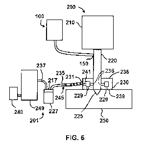
[0020] FIG. 6 provides a schematic overview of one embodiment of the
invention.
[0021] FIG. 7 provides another schematic overview of one embodiment of the
invention.
[0022] FIG. 8 provides a perspective view of foam-to-liquid transforming
device 227.
[0023] FIG. 9 provides a schematic cross-section of foam-to-liquid
transforming device
227 during operation.
[0024] FIG. 10 shows a detailed view of the interior of cover portion 217.
[0025] FIG. 11 provides a perspective view of a coupling member 267, which is
configured to couple conduit 237 to cover portion 217.
[0026] FIG. 12 provides an overview of material removal system 200 utilizing
foam-to-
liquid transforming device 328.
[0027] FIG. 13 provides a more detailed view of foam-to-liquid transforming
device 328
coupled to 235 and 237.
DETAILED DESCRIPTION
[0028] Embodiments of the present disclosure comprise systems and methods for
removing material (e.g., drilling, cutting, or grinding) that utilize foam for
lubrication,
cooling, and/or evacuation of residual particles.
[0029] Referring initially to FIG. 1, a schematic diagram of a foam-generating
system
100 illustrates a compressor 110, a pump 120, and a liquid reservoir 130, and
a foam
concentrate reservoir 140. System 100 further comprises a valve 135 configured
to
control the amount of liquid that is pumped from liquid reservoir 130. The
embodiment
shown in FIG. 1 also comprises a valve 145 configured to control the amount of
foam
concentrate that is released from foam concentrate reservoir 140. In other
embodiments,
foam concentrate may be added directly to liquid reservoir 130, eliminating
the need for
foam concentrate reservoir 140. In such embodiments, valve 145 can be
configured to
control the amount of pressurized air that is mixed with a liquid mixture of
water and
foam concentrate from liquid reservoir 130. In certain exemplary embodiments,
the foam
concentrate may be configured to reduce or neutralize the electrical
conductivity of the
-5-
CA 02766130 2011-12-20
WO 2010/078604 PCT/US2010/025716
liquid mixture or the resulting foam when the liquid mixture is combined with
pressurized air.
[0030] The embodiment shown in FIG. 1 includes a control switch 117 configured
to
start and stop compressor 110 as well as a control switch 127 configured to
start and stop
pump 120. In certain embodiments, a filter 121 is located between compressor
110 and
pump 120 or between compressor 110 and control switch 127. In specific
embodiments,
filter 121 may comprise a built-in moisture separator. In addition, system 100
comprises
a control switch 137 to control the flow of foam or liquid from an exit port
150 of system
100. Control switch 137 may be coupled to a solenoid valve or other flow
control
mechanism (not shown). System 100 further comprises a control switch 147
configured
to control the flow of pressured air and foam concentrate.
[0031] An exemplary embodiment of one method of operating system 100 to
generate
foam will now be described. It is understood that other exemplary methods are
within the
scope of the present invention, and that the disclosed method is provided only
for
purposes of example. During operation of system 100, an operator can
manipulate
control switch 117 so that compressor 110 begins operation. In specific
embodiments,
compressor 110 can have a pressure sensor 113 that provides a signal to a
control system
(not shown) that controls the pressure produced by compressor 110. In certain
embodiments, pressure sensor 113 provides a signal for compressor 110 to cease
operation when the pressure downstream of the compressor reaches a pre-
determined
high threshold level. In specific exemplary embodiments, pressure sensor 113
provides a
signal for compressor 110 to cease operation when the pressure reaches a high
threshold
value of approximately from 6 to about 12 bar. During operation of system 100,
pressure
sensor 113 can also send a signal to re-start compressor 110 if the pressure
downstream
of the compressor falls below a low threshold level. In specific embodiments,
pressure
sensor 113 can send a signal to re-start compressor 110 if the pressure falls
below a value
of approximately from about 2 to about 8 bar. It is understood that these
values are
provided as examples, and that other embodiments may have other pressure
ranges for
the operation of compressor 110.
-6-
CA 02766130 2011-12-20
WO 2010/078604 PCT/US2010/025716
[0032] In this exemplary method of operation, an operator manipulates control
switch
117 and allows compressor 110 to operate until the desired pressure is reached
and
pressure sensor 113 sends a signal for compressor 110 to cease operation. The
operator
may then manipulate control switch 127 to start pump 120. Pump 120 can then
pump
liquid from reservoir 130, through a check valve 134 and valve 135 to a mixer
156, which
couples conduit 171 (which contains liquid) and conduit 172 (which contains
compressed
air and foam concentrate).
[0033] The operator may then manipulate control switch 137 to allow liquid
from
reservoir 130 (via pump 120) to exit from exit port 150. Once the flow of
liquid from
exit port 150 has been established, the operator can then manipulate control
switch 147 to
allow the foam concentrate and pressurized air to flow to past a check valve
144 and to
mixer 156 (which couples the liquid conduit to the foam concentrate conduit).
The foam
concentrate and liquid can then be mixed in mixer 156, and a foam exits from
exit port
150.
[0034] The operator can adjust valve 135 to increase or decrease the amount of
liquid
that is pumped by pump 120 to exit port 150. The operator can also adjust
valve 145 to
adjust the amount of foam concentrate and pressurized air that is directed to
exit port 150.
In the schematic diagram of FIG. 1, the flow of liquid is represented by
arrows 139, while
the flow of foam concentrate and pressurized air is represented by arrow 149.
The
resulting foam is represented by arrow 159.
[0035] Foam concentrates include those known in the art and are generally
composed of
various surfactants which, when present in small amounts, facilitate the
formation of a
foam, or enhances its colloidal stability by inhibiting the coalescence of
bubbles.
Suitable foaming agents include "betaines", such as cocamidopropyl betaines,
also
referred to as 1 -propanaminium, 3-amino-N-(carboxymethyl)-N,N-dimethyl- N-
coco
acyl derivatives, inner salts, 1-Propanaminium, 3-amino-N-(carboxymethyl)-N,N-
dimethyl-, N-coco acyl derivatives, hydroxides, inner salts, or 1-
propanaminium, 3-
amino-N-(carboxymethyl)-N,N-dimethyl-, N-coco acyl derivatives, inner salts.
-7-
CA 02766130 2011-12-20
WO 2010/078604 PCT/US2010/025716
[0036] Referring now to FIG. 2A, a partial section view of an exemplary
embodiment of
a material removal system 200 is shown. Material removal system 200 utilizes
foam
from foam-generation system 100 to lubricate components and remove residual
material
from the cutting interface (e.g., the interface where the cutting element
engages the
workpiece). It is understood that the material removal system shown in FIG. 2A
is
merely one example of a material removal system that can utilize foam from
foam-
generation system 100, and that other exemplary material removal systems may
comprise
different configurations. The embodiment shown in FIG. 2A comprises a driver
or
actuator 210 configured to rotate a shaft 220 and a cutting element 225. In
the
embodiment shown, cutting element 225 is configured as a drill bit, and
actuator 210
comprises an electric motor. In other embodiments, actuator 210 may comprise
other
forms of actuation, including without limitation, an internal combustion
engine, hydraulic
driven actuator or pneumatically-driven actuator. Other embodiments may also
comprise
other types of cutting elements, including without limitation, a saw blade.
Specific
exemplary embodiments may comprise a diamond circular blade or a diamond wire.
Exemplary embodiments of material removal system 200 include without
limitation,
applications for use in wall sawing, or floor sawing. During operation of the
embodiment
shown in FIG. 2A, actuator 210 rotates shaft 220 and cutting element 225.
Cutting
element 225 engages a workpiece 250 and removes material from workpiece 250.
[0037] Referring now to FIG. 2B, material removal system 200 may also be used
with a
vacuum system 201 configured to remove foam and/or residual materials from the
cutting
interface. In the embodiment shown, vacuum system 201 comprises a vacuum
collar 230
that is coupled to a vacuum source 240 via a conduit 235 and a reservoir 249.
A more
detailed view of an exemplary embodiment of vacuum collar 230 (shown isolated
from
material removal system 200) is provided in FIG. 3.
[0038] As shown in FIG. 3, vacuum collar 230 comprises a body 273 with an
external
wall 234 and an inner wall 233 surrounding a inner bore 232. Vacuum collar 230
also
comprises a first axial wall 238 and second axial wall 239. In FIG. 3, collar
230 is shown
inverted, so that second axial wall 239 will normally be facing downward when
collar
230 is being used (as shown in FIG. 2). Conduit 235 is coupled to vacuum
collar 230 at
-8-
CA 02766130 2011-12-20
WO 2010/078604 PCT/US2010/025716
an external port 231. As shown in FIGS. 2 and 3, one or more radial suction
ports 236
extend from inner wall 233 and are in fluid communication with external port
231 and
conduit 235. In the specific embodiment shown, suction ports 236 extend to an
inner
cavity 241 that is in fluid communication with external port 231. In certain
embodiments, inner cavity 241 is a ring-shaped cavity that extends around
inner bore
230. Radial suction ports 236 may extend radially between inner bore 230 and
inner
cavity 241 in a manner similar to spokes within a wheel. In other exemplary
embodiments, vacuum collar 230 may comprise a single port coupled to conduit
235 and
not include a plurality of radial and axial suction ports.
[0039] In addition, vacuum collar 230 is configured so that one or more axial
suction
ports extend from second axial wall 239 and are in fluid communication with
inner cavity
241 and external port 231. It is understood that the embodiment shown in FIG.
3 is
merely exemplary, and that other vacuum collars within the scope of this
disclosure may
comprise a different configuration than that shown in FIG. 3. For example,
other
exemplary embodiments may comprise suction ports in a different configuration
from
that shown, and may include only radial or axial suction ports.
[0040] During operation, residual particles 245 are flushed from the interface
of cutting
element 225 and workpiece 250 by foam exiting from exit port 150 of foam
generation
system 100. The foam, along with residual particles 245, can then be collected
by
vacuum system 201. As used herein, the term "residual particles" is used to
describe
waste or scrap particles generated during the material removal process (e.g.,
material
shavings, dust, cutting slurries, etc.)
[0041] In the embodiment shown in FIG. 2B, foam from system 100 is directed
through
shaft 220 to the interface of cutting element 225 and work piece. In other
embodiments,
the foam may be initially directed to a different location from that shown in
FIG. 2.
Radial suction ports 236 and axial suction ports 229 are proximal to the
cutting interface
and serve as the initial entry point for the foam (and/or residual particles
245) to enter
vacuum system 201. Collar 230 is shown in a section view in FIG. 2, so that
the internal
features of the collar are visible. The foam and residual particles 245 can be
directed to
-9-
CA 02766130 2011-12-20
WO 2010/078604 PCT/US2010/025716
inner cavity 241 of collar 230 and to external port 231. The foam and residual
particles
245 may then flow through conduit 235 to reservoir 249 for collection.
[0042] Once the foam has been collected in reservoir 249, it can either be
disposed of or
recycled. In the embodiment shown in FIG. 2, a foam reducing agent 260 can be
injected
into reservoir 249 to reduce the foam back to a liquid and allow for the
liquid to be
disposed.
[0043] In other embodiments, the foam with residual particles 245 can be
reduced to a
liquid that is filtered and re-used in foam-generation system 100. Referring
now to FIG.
4, a foam reducing agent 262 is added to reservoir 249 to reduce the foam to a
liquid.
The liquid can then be filtered by filter 258 so that residual particles 245
are removed
from the liquid and sent to disposal container 261. The filtered liquid can
then be sent
back to system 100 (e.g., to liquid reservoir 130) to be re-used in the foam-
generation
system 100. This can reduce the amount of liquid consumed by foam-generation
system
100 and reduce costs. The embodiment shown and described in FIG. 4 also
creates a
closed-loop system that minimizes the impact of the foam on the environment.
It is
understood that the arrangement of the components shown in FIG. 5 is just one
of many
exemplary embodiments. For example, in other embodiments, the foam may be
filtered
to remove residual particles 245 prior to the addition of a foam reducing
agent.
[0044] Foam reducing agents are known in the art and include silicone
compounds such
as silica dispersed in polydimethylsiloxane, fatty amides, hydrocarbon waxes,
fatty acids,
fatty esters, fatty alcohols, fatty acid soaps, ethoxylates, mineral oils,
polyethylene glycol
esters, aqueous salt solutions, alkyl phosphate esters such as monostearyl
phosphate, and
the like as well as acetylenic diols, such as FOAM BLASTTM, or aliphatic
polyoxyethylene ethers, made from fatty alcohol ethoxylatse with
epichlorohydrin and
formed in a polymeric star configuration, commercially available, under the
trade name
DEHYDRANTM. A discussion of suitable agents may be found, for example, in U.S.
Pat.
No. 3,048,548 to Martin et al., U.S. Pat. No. 3,334,147 to Brunelle et al.,
and U.S. Pat.
No. 3,442,242 to Rue et al., the disclosures of which are incorporated by
reference herein.
-10-
CA 02766130 2011-12-20
WO 2010/078604 PCT/US2010/025716
[0045] Referring now to FIG. 5, in this embodiment the foam is recycled rather
than
disposed. The foam can be filtered via filter 248 to remove residual particles
245 from
the foam. Residual particles 245 that are filtered from the foam can be sent
to a disposal
container 261. The filtered foam can be recycled back (through recycle conduit
247) to
exit port 150. At that point, the filtered foam can be combined with the foam
generated
from system 100. This can reduce the total amount of foam that is required to
be
generated by system 100 and reduce both the cost of operation and the amount
of waste
generated. As described herein, this recycling of the foam creates a closed-
loop system
for the foam utilization. The closed-loop system can reduce the likelihood
that foam will
impact the surrounding environment. This can be particularly important when
material
removal system 200 is being used in environments where it is desirable to
minimize or
eliminate the exposure to foam (e.g., a finished interior environment). In
such
environments, objects such as furniture, drywall, flooring, etc. can be
negatively
impacted by liquid. The use of foam, instead of liquid, minimizes the
potential negative
impacts by improving the confinement in a limited area of the foam. Exemplary
embodiments may be utilized with the foam system described herein with or
without the
vacuum systems shown and described in this disclosure.
[0046] Referring now to FIGS. 6-11, an exemplary embodiment is similar to the
embodiment disclosed in FIG. 2. However, rather than a foam reducing agent,
this
exemplary embodiment comprises a foam-reduction or foam-to-liquid transforming
device 227 in fluid communication with vacuum collar 230 via a conduit 235.
Foam-to-
liquid transforming device 227 is also in fluid communication with reservoir
249 via a
conduit 237. In the specific embodiment shown, foam-to-liquid transforming
device 227
comprises a removable cover portion 217 that is coupled to conduits 235 and
237. FIGS.
6 and 7 provide schematic overviews of the system, while FIG. 8 provides a
perspective
view of foam-to-liquid transforming device 227. FIG. 9 provides a schematic
cross-
section of foam-to-liquid transforming device 227 during operation, and FIG.
10 shows a
detailed view of the interior of cover portion 217. FIG. 11 provides a
perspective view of
a coupling member 267, which is configured to couple conduit 237 to cover
portion 217.
-11-
CA 02766130 2011-12-20
WO 2010/078604 PCT/US2010/025716
[0047] During operation, vacuum source 240 can draw foam 270 (and residual
particles
245) from collar 230 through conduit 235 to foam-to-liquid transforming device
227. In
the embodiment shown, conduits 235 and 237 are coupled to cover portion 217 of
foam-
to-liquid transforming device 227 via coupling members 265 and 267,
respectively. As
shown in FIG. 9, foam 270 enters an upper portion 257 of foam-to-liquid
transforming
device 227 via conduit 235 and accumulates in foam-to-liquid transforming
device 227
until foam 270 reaches coupling member 267 and conduits 215.
[0048] As vacuum source 240 draws foam 270 through coupling member 267, foam
270
is directed through a plurality of conduits 215 that each have a diameter that
is smaller
than the diameter of conduit 235 and 237. In exemplary embodiments, the sum of
the
cross-sectional areas of conduits 215 is less than the cross sectional area of
conduit 237.
[0049] Referring specifically to FIG. 11, in this exemplary embodiment
coupling
member 267 comprises a flange portion 290, an extension 291, and conduits 215.
Flange
portion 290 provides a mounting surface that allows coupling member 267 to be
coupled
to cover portion 217, and extension 291 allows coupling member 267 to be
coupled to
conduit 237. Conduits 215 extend through flange portion 290 (while extension
291 does
not) so that fluids or foam 270 that pass through coupling member 267 are
forced to pass
through conduits 215.
[0050] As foam 270 is drawn through conduits 215, the diameter of each conduit
is
sized sufficiently small enough to cause a portion of the foam to convert to
liquid.
During operation the bubbles in foam 270 are forced against each other (and
against the
walls of each conduit 215) so that the pressure exerted on bubbles in foam 270
is
increased. When the pressure is increased sufficiently, the bubbles collapse
and the
volume of foam 270 is reduced as it becomes a foam and liquid mixture. This
reduction
in volume of foam 270 allows for material removal system 200 to be operated
for longer
periods of time (as compared to material removal systems that do not reduce
the volume
of foam 270). If the volume of foam 270 is not reduced, the capacity of
reservoir 249 can
be a limiting factor on the maximum operating time of material removal system
200.
When reservoir 249 is filled with foam, the operation of material removal
system 200
-12-
CA 02766130 2011-12-20
WO 2010/078604 PCT/US2010/025716
should be stopped in order to remove the foam and/or liquid from reservoir
249. By
reducing the volume of foam 270 prior to it entering reservoir 249, the
maximum
operation time of material removal system 200 can be extended.
[0051] In specific embodiments, the diameter of one or more conduits in the
plurality of
conduits 215 may be between 4 and 8 millimeters, or more specifically between
5 and 7
millimeters. In a specific embodiment, the diameter of one or more conduits in
the
plurality of conduits 215 is approximately 6 millimeters. In certain specific
embodiments, the length of one or more conduits in the plurality of conduits
215 may be
between 50 and 500 millimeters, or between 60 and 400 millimeters, or between
70 and
300 millimeters, or between 80 and 200 millimeters, or between 90 and 100
millimeters.
In a specific embodiment the length of one or more conduits in the plurality
of conduits
215 is approximately 100 millimeters.
[0052] Once the liquid and foam mixture has been collected in reservoir 249,
it can
either be disposed of or filtered and recycled for use. In specific
embodiments, the liquid
that results from the collapsed foam can be converted back to foam via foam
generating
system 100 prior to re-use.
[0053] Referring now to FIGS. 12 and 13, in certain embodiments, a foam-to-
liquid
transforming device 328 may not comprise a reservoir that is external to
conduits 235 and
237. FIG. 12 provides an overview of material removal system 200 utilizing
foam-to-
liquid transforming device 328, while FIG. 13 provides a more detailed view of
foam-to-
liquid transforming device 328 coupled to 235 and 237.
[0054] Foam-to-liquid transforming device 328 may be configured generally
similar to
coupling member 267, e.g., foam-to-liquid transforming device 328 comprises a
flange
portion 390, an extension 391, and a plurality of conduits 315. However, foam-
to-liquid
transforming device 328 may also comprise an additional extension portion 392
so that it
may be coupled to both conduits 235 and 237. When foam-to-liquid transforming
device
328 is coupled to conduits 235 and 237, conduits 315 are placed in fluid
communication
with conduits 235 and 237. In specific embodiments, conduits 315 are placed in
line with
(e.g., collinear with) conduits 235 and 237 such that the outer circumference
of conduit
-13-
CA 02766130 2011-12-20
WO 2010/078604 PCT/US2010/025716
235 and 237 circumscribe conduits 315. During operation, conduits 315 act upon
the
foam bubbles passing through them in the same general manner described above
with
respect to conduits 215, and transform the foam to liquid.
[0055] Although various representative embodiments of this invention have been
described above with a certain degree of particularity, those skilled in the
art could make
numerous alterations to the disclosed embodiments without departing from the
spirit or
scope of the inventive subject matter set forth in the specification and
claims. For
example, the material removal system illustrated and described herein is
configured with
a shaft and rotating cutting element. In addition, other embodiments may use a
centrifuge, cyclone separator or press to separate the residual particles from
the foam or
liquid to be used in recycling. However, other material removal systems that
utilize the
foam generating / recycling system described herein may utilize other types of
cutting
element. Other embodiments may have components with different configurations
than
those shown in the attached figures.
[0056] Joinder references (e.g., attached, coupled, connected) are to be
construed
broadly and may include intermediate members between a connection of elements
and
relative movement between elements. As such, joinder references do not
necessarily
infer that two elements are directly connected and in fixed relation to each
other. In some
instances, in methodologies directly or indirectly set forth herein, various
steps and
operations are described in one possible order of operation, but those skilled
in the art
will recognize that steps and operations may be rearranged, replaced, or
eliminated
without necessarily departing from the spirit and scope of the present
invention. It is
intended that all matter contained in the above description or shown in the
accompanying
drawings shall be interpreted as illustrative only and not limiting. Changes
in detail or
structure may be made without departing from the spirit of the invention as
defined in the
appended claims.
[0057] The following paragraphs enumerated consecutively from 1 through eighty
(80)
provide for various aspects of the present invention. In one embodiment, in a
first
-14-
CA 02766130 2011-12-20
WO 2010/078604 PCT/US2010/025716
paragraph (1), the present invention provides a system for removing material,
the system
comprising:
a cutting element;
an actuator configured to actuate the cutting element;
a shaft coupled to the actuator and the cutting element; and
a foam generation system configured to direct foam to the cutting element.
[0058] 2. The system of paragraph 1 wherein the residual particles are flushed
from the
system by a foam.
[0059] 3. The system of paragraph 1 further comprising a vacuum system
configured to
remove residual particles created during operation of the system, wherein the
vacuum
system comprises a collar that extends around the shaft.
[0060] 4. The system of paragraph 3 wherein the collar comprises an internal
cavity and
one or more suction ports in fluid communication with the internal cavity.
[0061] 5. The system of paragraph 4 wherein the plurality of suction ports
comprises
radial suction ports and axial suction ports.
[0062] 6. The system of paragraph 3 wherein the collar comprises an internal
wall
surrounding a bore and a plurality of suction ports extending from the
internal wall.
[0063] 7. The system of paragraph 3 wherein the collar comprises an axial wall
and a
plurality of suction ports extending from the internal wall.
[0064] S. The system of paragraph 3 wherein the vacuum system comprises a
vacuum
source and a conduit coupled to the collar.
[0065] 9. The system of paragraph 8 wherein the conduit is coupled to the
collar at an
external port.
[0066] 10. The system of paragraph 9 wherein the collar comprises a plurality
of suction
ports in fluid communication with the external port.
[0067] 11. The system of paragraph 1 wherein the cutting element comprises a
drill bit.
-15-
CA 02766130 2011-12-20
WO 2010/078604 PCT/US2010/025716
[0068] 12. The system of paragraph 1 wherein the cutting element comprises a
saw
blade.
[0069] 13. A method of utilizing foam in a material removal system, the method
comprising:
providing an actuator, a cutting element, and a workpiece;
actuating the cutting element with the actuator;
providing a foam from a foam-generating system;
engaging the cutting element with the workpiece at a cutting element
interface;
directing the foam to the cutting interface;
applying a foam-reducing agent to the foam after the foam has been directed to
the cutting interface, wherein the foam-reducing agent reduces the foam to
a liquid;
filtering the liquid to remove residual particles and produce a filtered
liquid; and
directing the filtered liquid to the foam-generating system.
[0070] 14. The method of paragraph 13 wherein the filtered liquid is combined
with a
foam concentrate in the foam-generating system to produce foam.
[0071] 15. The method of paragraph 13 further comprising removing the foam
from the
cutting interface with a vacuum system.
[0072] 16. The method of paragraph 15 wherein the vacuum system comprises a
collar
proximal to the cutting interface.
[0073] 17. The method of paragraph 16 wherein the collar comprises an internal
cavity
and one or more suction ports in fluid communication with the internal cavity.
[0074] 18. The method of paragraph 17 wherein the plurality of suction ports
comprises
radial suction ports and axial suction ports.
-16-
CA 02766130 2011-12-20
WO 2010/078604 PCT/US2010/025716
[0075] 19. The method of paragraph 16 wherein the collar comprises an internal
wall
surrounding a bore and a plurality of suction ports extending from the
internal wall.
[0076] 20. The method of paragraph 16 wherein the collar comprises an axial
wall and a
plurality of suction ports extending from the internal wall.
[0077] 21. The method of paragraph 16 wherein the vacuum system comprises a
vacuum
source and a conduit coupled to the collar.
[0078] 22. The method of paragraph 21 wherein the conduit is coupled to the
collar at an
external port.
[0079] 23. The system of paragraph 22 wherein the collar comprises a plurality
of
suction ports in fluid communication with the external port.
[0080] 24. A system for generating foam, the system comprising:
a pump;
a liquid reservoir comprising a liquid, wherein the pump is configured to pump
liquid from the liquid reservoir;
a compressor configured to produce compressed air;
a foam concentrate reservoir comprising a foam concentrate;
a first valve configured to control an amount of foam concentrate that is
released
from the foam concentrate reservoir;
a second valve configured to control the amount of liquid pumped from the
liquid
reservoir;
a first pressure sensor configured to stop operation of the compressor when an
air
pressure downstream of the compressor reaches a high threshold value;
a second pressure sensor configured to start operation of the compressor when
the
air pressure downstream of the compressor reaches a low threshold value;
a first conduit comprising liquid from the liquid reservoir;
a second conduit comprising compressed air and the foam concentrate; and
-17-
CA 02766130 2011-12-20
WO 2010/078604 PCT/US2010/025716
a mixer coupling the first conduit and the second conduit, wherein the foam
concentrate and liquid are combined in the mixer to produce a foam.
[0081] 25. The system of paragraph 24, wherein the foam is directed to a
material
removal system.
[0082] 26. The system of paragraph 25, wherein the foam is recycled from the
material
removal system to the foam generating system.
[0083] 27. The system of paragraph 26, further comprising a foam-reducing
agent
configured to reduce the foam to liquid when the foam is being recycled.
[0084] 28. The system of paragraph of paragraph 25, further comprising a
filter to filter
residual particles from the liquid.
[0085] 29. The system of paragraph 23, wherein the material removal system
comprises
a drill.
[0086] 30. The system of paragraph 24 wherein the high threshold value is
approximately from about 6 to about 12 bar.
[0087] 31. The system of paragraph 24 wherein the low threshold value is
approximately
from about 2 to about 8 bar.
[0088] 32. The system of paragraph 24, wherein a premixed foam concentrate and
liquid is placed in a liquid reservoir.
[0089] 33. A foam-to-liquid transforming device comprising:
a coupling member comprising a plurality of coupling member conduits, wherein:
the coupling member is configured to couple a first vacuum conduit and a
second vacuum conduit;
the plurality of coupling member conduits each have a diameter smaller
than the diameter of the first vacuum conduit and smaller than the
diameter of the second vacuum conduit; and
-18-
CA 02766130 2011-12-20
WO 2010/078604 PCT/US2010/025716
the plurality of coupling member conduits are in fluid communication with
the first vacuum conduit and with the vacuum second conduit.
[0090] 34. The foam-to-liquid transforming device of paragraph 33, wherein the
plurality of coupling member conduits are collinear with the first and second
vacuum
conduits when the foam-to-liquid transforming device is coupled to the first
and second
vacuum conduits.
[0091] 35. A foam-to-liquid transforming device comprising:
a reservoir;
a first conduit in fluid communication with the reservoir;
a second conduit in fluid communication with the reservoir;
a plurality of conduits in fluid communication with the second conduit,
wherein
each conduit in the plurality of conduits has a diameter that is less than the
diameter of the second conduit.
[0092] 36. The foam-to-liquid transforming device of paragraph 35 wherein the
diameter
of one or more conduit in the plurality of conduits is between approximately 4
millimeters and 8 millimeters.
[0093] 37. The foam-to-liquid transforming device of paragraph 35 wherein the
diameter
of one or more conduit in the plurality of conduits is between approximately 5
millimeters and 7 millimeters.
[0094] 38. The foam-to-liquid transforming device of paragraph 35 wherein the
diameter
of one or more conduit in the plurality of conduits is approximately 6
millimeters.
[0095] 39. The foam-to-liquid transforming device of paragraph 35 wherein the
plurality
of conduits comprises between 2 and 10 conduits.
[0096] 40. The foam-to-liquid transforming device of paragraph 35 wherein the
plurality
of conduits comprises between 3 and 9 conduits.
[0097] 41. The foam-to-liquid transforming device of paragraph 35 wherein the
plurality
of conduits comprises between 4 and 8 conduits.
-19-
CA 02766130 2011-12-20
WO 2010/078604 PCT/US2010/025716
[0098] 42. The foam-to-liquid transforming device of paragraph 35 wherein the
plurality
of conduits comprises between 5 and 7 conduits.
[0099] 43. The foam-to-liquid transforming device of paragraph 35 wherein the
length
of one or more conduit in the plurality of conduits is between approximately
50
millimeters and 500 millimeters.
[00100] 44. The foam-to-liquid transforming device of paragraph 35 wherein the
length of one or more conduit in the plurality of conduits is between
approximately 60
millimeters and 400 millimeters.
[00101] 45. The foam-to-liquid transforming device of paragraph 35 wherein the
length of one or more conduit in the plurality of conduits is between
approximately 70
millimeters and 300 millimeters.
[00102] 46. The foam-to-liquid transforming device of paragraph 35 wherein the
length of one or more conduit in the plurality of conduits is between
approximately 80
millimeters and 200 millimeters.
[00103] 47. The foam-to-liquid transforming device of paragraph 35 wherein the
length of one or more conduit in the plurality of conduits is between
approximately 90
millimeters and 100 millimeters.
[00104] 48. The foam-to-liquid transforming device of paragraph 35 wherein the
length of one or more conduit in the plurality of conduits is approximately
100
M Biters. 49. The foam-to-liquid transforming device of paragraph 35 wherein a
first conduit in the plurality of conduits is adjacent to a second conduit in
the plurality of
conduits.
[00106] 50. The foam-to-liquid transforming device of paragraph 35 wherein the
plurality of conduits are located within a coupling member configured to
couple the
second conduit to reservoir.
[00107] 51. The foam-to-liquid transforming device of paragraph 35 wherein the
plurality of conduits are located within the second conduit.
-20-
CA 02766130 2011-12-20
WO 2010/078604 PCT/US2010/025716
[00108] 52. The foam-to-liquid transforming device of paragraph 35 wherein the
foam-to-liquid transforming device comprises a removable cover portion, and
wherein
the plurality of conduits are coupled to the removable cover portion.
[00109] 53. The foam-to-liquid transforming device of paragraph 35 wherein the
plurality of conduits are coupled to an upper portion of the reservoir.
[00110] 54. A system for removing material, the system comprising:
a cutting element;
an actuator configured to actuate the cutting element;
a shaft coupled to the actuator and the cutting element;
a vacuum system configured to remove residual particles created during
operation
of the system, wherein the vacuum system comprises:
a vacuum source;
a first reservoir; and
a collar that extends around the shaft;
a foam generation system configured to generate foam and direct the foam
proximal to the collar; and
a foam-to-liquid transforming device configured to reduce the foam, wherein
the
foam-to-liquid transforming device comprises a plurality of conduits
configured to convert the foam to liquid as the foam passes through the
plurality of conduits.
[00111] 55. The system of paragraph 54 wherein the foam-to-liquid transforming
device is coupled to a first conduit in fluid communication with the collar
and wherein
the foam-to-liquid transforming device is coupled to a second conduit in fluid
communication with the first reservoir.
[00112] 56. The system of paragraph 54 wherein the plurality of conduits are
in
fluid communication with the second conduit, wherein each conduit in the
plurality of
conduits has a diameter that is less than the diameter of the second conduit.
- 21 -
CA 02766130 2011-12-20
WO 2010/078604 PCT/US2010/025716
[00113] 57. A method of reducing a volume of foam, the method comprising:
providing a first reservoir, a vacuum source, a first conduit, and a second
conduit,
and a plurality of conduits wherein:
the first conduit is in fluid communication with the first reservoir;
the second conduit is in fluid communication with the vacuum
source and the first reservoir; and
the sum of the cross-sectional area of the plurality of conduits is
less than the cross-sectional area of the second conduit;
operating the vacuum source to create a vacuum on the first reservoir, the
first
conduit and the second conduit; and
drawing foam through the first conduit, into the first reservoir, through the
plurality of conduits and into the second conduit.
[00114] 58. The method of paragraph 57 wherein the volume of foam is reduced
as the foam is drawn through the plurality of conduits.
[00115] 59. The method of paragraph 57 wherein a portion of the foam is
converted to a liquid as the foam is drawn through the plurality of conduits.
[00116] 60. The method of paragraph 59 wherein the second conduit is in fluid
communication with a second reservoir and wherein the liquid is collected in
the second
reservoir.
[00117] 61. A system for removing material, the system comprising:
[00118] a cutting element;
[00119] an actuator configured to actuate the cutting element;
[00120] a shaft coupled to the actuator and the cutting element;
[00121] a vacuum system configured to remove residual particles created during
operation of the system, wherein the vacuum system comprises:
[00122] a vacuum source;
-22-
CA 02766130 2011-12-20
WO 2010/078604 PCT/US2010/025716
[00123] a first reservoir; and
[00124] a collar that extends around the shaft;
[00125] a foam generation system configured to generate foam and direct the
foam
proximal to the collar; and
[00126] a foam-to-liquid transforming device configured to reduce the foam,
wherein the foam-to-liquid transforming device comprises a plurality of
conduits
configured to convert the foam to liquid as the foam passes through the
plurality of
conduits.
[00127] 62. The system of paragraph 61, wherein the foam-to-liquid
transforming
device is coupled to a first conduit in fluid communication with the collar
and wherein
the foam-to-liquid transforming device is coupled to a second conduit in fluid
communication with the first reservoir.
[00128] 63. The system of either of paragraphs 61 or 62, wherein the plurality
of
conduits are in fluid communication with the second conduit, wherein each
conduit in the
plurality of conduits has a diameter that is less than the diameter of the
second conduit.
[00129] 64. The system of any of paragraphs 61 through 63, wherein the
diameter
of one or more conduit in the plurality of conduits is between approximately 4
millimeters
[00130] 65. The system of any of paragraphs 61 through 64, wherein the
plurality
of conduits comprises between 2 and 10 conduits.
[00131] 66. The system of any of paragraphs 61 through 65, wherein the length
of
one or more conduit in the plurality of conduits is between approximately 50
millimeters
and 500 millimeters.
[00132] 67. The system of any of paragraphs 61 through 66, wherein a first
conduit in the plurality of conduits is adjacent to a second conduit in the
plurality of
conduits.
-23-
CA 02766130 2011-12-20
WO 2010/078604 PCT/US2010/025716
[00133] 68. The system of any of paragraphs 61 through 67, wherein the
plurality
of conduits are located within a coupling member configured to couple the
second
conduit to reservoir.
[00134] 69. The system of any of paragraphs 61 through 67, wherein the
plurality
of conduits are located within the second conduit.
[00135] 70. The system of any of paragraphs 61 through 69, wherein the foam-to-
liquid transforming device comprises a removable cover portion, and wherein
the
plurality of conduits are coupled to the removable cover portion.
[00136] 71. The system of any of paragraphs 61 through 69, wherein the
plurality
of conduits are coupled to an upper portion of the reservoir.
[00137] 72. A method of reducing a volume of foam, the method comprising:
[00138] providing a first reservoir, a vacuum source, a first conduit, and a
second
conduit, and a plurality of conduits wherein:
[00139] the first conduit is in fluid communication with the first reservoir;
[00140] the second conduit is in fluid communication with the vacuum source
and
the first reservoir; and
[00141] the sum of the cross-sectional area of the plurality of conduits is
less than
the cross-sectional area of the second conduit;
[00142] operating the vacuum source to create a vacuum on the first reservoir,
the
first conduit and the second conduit; and
[00143] drawing foam through the first conduit, into the first reservoir,
through the
plurality of conduits and into the second conduit.
[00144] 73. The method of paragraph 72, wherein the volume of foam is reduced
as the foam is drawn through the plurality of conduits.
[00145] 74. The method of paragraph 72, wherein a portion of the foam is
converted to a liquid as the foam is drawn through the plurality of conduits.
-24-
CA 02766130 2011-12-20
WO 2010/078604 PCT/US2010/025716
[00146] 75. The method of paragraph 72, wherein the second conduit is in fluid
communication with a second reservoir and wherein the liquid is collected in
the second
reservoir.
[00147] 76. The method of any of paragraphs 72 through 75, wherein the
diameter
of one or more conduit in the plurality of conduits is between approximately 4
millimeters
[00148] 77. The method of any of paragraphs 72 through 76, wherein a first
conduit in the plurality of conduits is adjacent to a second conduit in the
plurality of
conduits.
[00149] 78. The method of any of paragraphs 72 through 77, wherein the
plurality
of conduits are located within a coupling member configured to couple the
second
conduit to reservoir.
[00150] 79. The method of any of paragraphs 72 through 77, wherein the foam-to-
liquid transforming device comprises a removable cover portion, and wherein
the
plurality of conduits are coupled to the removable cover portion.
[00151] 80. The method of any of paragraphs 72 through 77, wherein the
plurality
of conduits are coupled to an upper portion of the reservoir.
[00152] Although the present invention has been described with reference to
preferred embodiments, persons skilled in the art will recognize that changes
may be
made in form and detail without departing from the spirit and scope of the
invention.
-25-
CA 02766130 2011-12-20
WO 2010/078604 PCT/US2010/025716
REFERENCES
The following references are incorporated by reference herein:
U.S. Patent 3,589,468
U.S. Patent 5,128,178
U.S. Patent 6,673,572
U.S. Patent Pub. 2002/0115390
U.S. Patent 6,792,375
U.S. Patent Pub. 2003/0167728
U.S. Patent 6,790,245
U.S. Patent 6,890,131
U.S. Patent 6,026,618
U.S. Patent 6,071,047
U.S. Patent 6,588,516
U.S. Patent 6,609,668
U.S. Patent 2,578,040
U.S. Patent 3,518,917
U.S. Patent 4,325,663
U.S. Patent 4,662,802
U.S. Patent 5,660,240
U.S. Patent 5,800,104
-26-