Note : Les descriptions sont présentées dans la langue officielle dans laquelle elles ont été soumises.
CA 02766414 2015-05-05
1
CONVEYING APPARATUS AND SUPPORT DEVICE
The invention relates generally to the field of
conveying technology, and more particularly to a
conveying apparatus and to a supporting device for a
conveying apparatus.
BACKGROUND
It is known for conveying material to be conveyed as
individual entities, e.g. goods, people or animals, or
as bulk material in conveying apparatuses with planar
conveying means. Such conveying means either are
conveying belts or have interlinked, typically rigid
elements which can be displaced in relation to one
another in order to be able to negotiate curves. The
elements form an essentially flat surface, on which the
conveying material is conveyed. These interlinked
conveying means are known, for example, as mat-top
chains, flat-top chains, plate-top chains (flexbelts,
chain belts, carrier chains). They are referred to
jointly hereinbelow as mat-top chains (flexbelts).
Depending on the type of conveying means, the ways of
mounting same differ: mat-top chains are supported, for
example, two-dimensionally and slide on sliding rails
or sliding surfaces. Depending on the loading by the
conveying material, this results in high frictional
forces and corresponding motive forces for moving the
mat-top chain, and also in wear. Other embodiments of
mat-top chains have, as part of the mat-top chain
itself, rollers which run along therewith and roll on a
surface. Conveying belts, in contrast, usually roll on
fixed rollers, i.e. ones which are mounted such that
they can be rotated at a fixed location. The rotatable
mounting of the rollers results in wear and limits the
loading capability of a conveying apparatus.
CA 02766414 2016-10-19
2
FR 2 309 433, furthermore, describes a conveying
apparatus for conveying individual entities. The
conveying apparatus contains a chain conveyor made of
movable chain links, which is driven and on which items
are transported. The chain conveyor is supported by a
supporting device. The supporting device comprises
circulating rollers, which are connected to one another
via chains arranged laterally on the rollers. The
rollers are retained on the lateral chains such that
they can be rotated via axial shafts.
DE 26 124 68 describes a conveying apparatus with a
transporting belt which is supported by a grating
arrangement. The grating arrangement comprises two
parallel roller chains, which together carry
cylindrical transverse bars. The roller chains contain
rollers which are mounted such that they can be rotated
via slide bearings and over which the grating
arrangement rolls.
EP 0 978 465, in turn, describes a device for moving
components linearly. The transporting device contains a
transporting belt, which is fixed in a frictional
manner between carriages and rolling bars. The rolling
bars are mounted on rolling bodies.
All the known devices have the disadvantage that they
have a complicated construction and comprise a large
number of individual parts. They are therefore
expensive to produce and to maintain. Many devices, in
addition, have mechanical bearings with shafts,
rolling-contact bearings, etc., which render the device
susceptible to disruption and wear.
SUMMARY OF EMBODIMENTS OF THE INVENTION
In accordance with an aspect of at least one embodiment
of the invention, there is provided a conveying
apparatus comprising: a moving, planar conveying means
CA 2766914 2017-04-24
2a
for conveying bulk material or individual entities, a
supporting device arranged beneath the conveying means,
said supporting device comprising a plurality of roller
bodies, wherein each roller body of the plurality of
roller bodies circulates around a supporting body in a
closed circuit and each roller body comprises a
= multiplicity of rollers connected to one another by a
flexible connecting body and spaced apart from one
another by the flexible connecting body, wherein each
roller body, on one side, has the rollers rolling along
a non-circulAr path on the supporting body and, on the
other side, supports the conveying means by the rollers
rolling on the conveying means itself or on a belt
which runs along between the conveying means and
rollers, and wherein each one of the roller bodies can
be moved separately from the other roller bodies.
In accordance with an aspect of at least one embodiment
of the invention, there is provided a supporting device
for a conveying apparatus, said conveying apparatus
comprising a moving, planar conveying means for
conveying bulk material or individual entities, said
supporting device being arranged beneath the conveying
means and comprising a plurality of roller bodies,
wherein each roller body of the plurality of roller
bodies circulates around a supporting body in a closed
circuit and each roller body comprises a multiplicity
of rollers connected to one another by a flexible
connecting body and spaced apart from one another by
the flexible connecting body, wherein each roller body,
on one side, has the rollers rolling along a non-
circular path on the supporting body and, on the other
side, supports the conveying means by the rollers
rolling on the conveying means itself or on a belt
which runs along between the conveying means and
rollers, and wherein each one of the roller bodies can
be moved separately from the other roller bodies,
CA 2766914 2017-04-24
2b
wherein the rollers in each roller body are arranged in
a multiplicity of successive rows with just one roller
per row or with a plurality of coaxially arranged
rollers per row, and wherein each roller body comprises
a flexible, planar connecting body, and the rollers are
=
inserted in openings of the connecting body, and
wherein the connecting body comprises a plurality of
layers arranged parallel to one another.
In accordance with an aspect of at least one embodiment
of the invention, there is provided a roller body for a
supporting device of a conveying apparatus, said
conveying apparatus comprising a moving, planar
conveying means for conveying bulk material or
individual entities, said supporting device being
arranged beneath the conveying means and comprising a
plurality of roller bodies, wherein each roller body of
the plurality of roller bodies circulates around a
supporting body in a closed circuit and each roller
body comprises a multiplicity of rollers connected to
one another by a flexible connecting body and spaced
apart from one another by the flexible connecting body,
wherein each roller body, on one side, has the rollers
rolling along a non-circular path on the supporting
body and, on the other side, supports the conveying
means by the rollers rolling on the conveying means
itself or on a belt which runs along between the
conveying means and rollers, and wherein each one of
the roller bodies can be moved separately from the
other roller bodies, wherein the rollers in the roller
body are arranged in a multiplicity of successive rows
with just one roller per row or a plurality of
coaxially arranged rollers per row, and wherein each
roller body comprises a flexible, planar connecting
body, and the rollers are inserted in openings of the
connecting body, and the rollers are inserted in
openings of the connecting body, and wherein
I I
CA 2766914 2017-04-24
2c
the connecting body comprises a plurality of layers
arranged parallel to one another.
In accordance with an aspect of at least one embodiment
of the invention, there is provided a conveying
apparatus of the type mentioned in the introduction
=
CA 02766414 2015-05-05
3
which has a high loading capability, in particular in
the vertical direction, and nevertheless runs smoothly,
that is to say with a low level of friction. According
to at least one embodiment the tensile force for the
drive of the conveying means is reduced. According to
at least one embodiment it possible for such a
conveying apparatus to be constructed in lightweight
form, i.e. using straightforward, uncomplicated and
non-specific parts made of cost-effective and light-
weight materials.
In accordance with an aspect of at least one embodiment
of the invention, there is provided a supporting device
which, using straightforward means, makes it possible
to support moving, planar and high-load-bearing
conveying means of such a conveying apparatus, and
preferably also prevents sagging of elements of the
conveying means in the process.
The conveying apparatus according to an embodiment of
the invention can be used for conveying bulk material
or individual entities, for example material or
entities which is/are at rest or which can move of
their own accord, in particular people or other living
things, e.g. animals. The term individual entities
consequently covers both goods and living things, for
example people, animals and plants. The conveying
apparatus may be, for example, a conveying belt for
conveying material or entities which is/are at rest or
which can move of their own accord, in particular
animals or people with and without baggage, as found,
for example, in airports. The conveying belts may run
on a level or in a slightly inclined manner. Conveying
belts for conveying people over relatively long
distances are also referred to as moving walkways or
moving sidewalks. The conveying means may be a belt or
a mat-top chain. Such moving sidewalks or walkways, in
particular inclined ones, are also found, for example
in supermarkets.
CA 02766414 2015-05-05
4
Furthermore, the conveying apparatus can also be used
for people or animals to walk or run on. It is thus
possible for the conveying apparatus to be, for
example, a treadmill, which allows people or animals to
undergo training, therapy and/or investigative
procedures. In the case of such treadmills, the
conveying means moves beneath the user, and therefore
the user is encouraged to walk or run on the conveying
means counter to the conveying direction. In this way,
the user walks or runs without advancing in space to
any significant extent. The more or less fixed-position
movement of the user on the treadmill means that, on
the one hand, a trainer or medical practitioner can
observe the user to good effect and, on the other hand,
there is no need for a complete track, which takes up a
corresponding amount of space, for the purpose of
carrying out the walking or running movement. The term
"belt" in this context is likewise intended to cover
all the embodiments of planar conveying means, such as
belts or mat-top chains, mentioned in the introduction
and hereinbelow.
The conveying apparatus comprises a moving, planar
conveying means for conveying bulk material or
individual entities, for example goods or living
things, e.g people or animals. For this purpose, the
conveying means has arranged beneath it one or more
supporting devices, which each have a roller body with
a multiplicity of rollers. In this case, the roller
body, on one side, has the rollers rolling along a non-
circular path on the supporting body and, on the other
side, in a supporting region, supports the conveying
means by the rollers rolling on the conveying means
itself or on a belt which runs along between the
conveying means and rollers (the belt is regarded as
being part of the roller body). The rollers are
connected to one another, and spaced apart from one
another, by a flexible connecting body. The supporting
CA 02766414 2015-05-05
body expediently contains a central body, along which
the roller body rolls, and in each case a side-wall
body, which is fitted laterally on the central body and
via which the supporting device rests on an underlying
5 surface.
The conveying means is preferably a mat-top chain (or
flat-top chain, plate-top chain, etc.) or a conveying
belt. The bearing or retaining points of the rollers,
via which the rollers are connected to the connecting
body and guided, do not absorb any forces for
supporting the conveying means and the conveying
material. This means that the conveying means can be
supported with very low frictional losses. The
connecting body serves for conveying, and spacing
apart, the rollers in the non-loaded regions of the
circulatory path around the supporting body or of the
path along the supporting body. Corresponding to the
low friction and the roller-mounted movement of the
conveying means, the wear and the motive forces for
moving the conveying means are also low. Fewer drive
motors and/or less powerful drive motors are required.
The rollers are preferably arranged to circulate around
the supporting body, in particular to circulate in a
closed circuit, also referred to as a circulatory path.
Other embodiments of the invention, rather than having
a closed circuit, have, for example, a rectilinear
path. A supporting region, in which the conveying means
rolls on the roller body, is preferably planar, that is
to say non-curved, in both cases. It is possible here
for the supporting region to run horizontally or also
obliquely, i.e. for the purpose of conveying the
conveying material upward or downward.
In an embodiment, a supporting region is present only
at certain locations along the conveying means,
expediently at locations where loading is increased,
for example locations at which conveying material is
CA 02766414 2015-05-05
6
accumulated. At other locations along the conveying
means, conventional support, for example with
slideways, may be provided.
It is thus possible for a flat conveying section of
essentially any desired length to be supported by a
roller body and supporting body of corresponding
length. The roller body preferably extends essentially
over the entire width of the conveying means, that is
to say, for example, over more than 3/4 or 4/5 of the
width. This means that the conveying means is supported
at most locations (as seen in cross section) and can
itself be of relatively lightweight design.
In an embodiment a plurality of roller bodies together
support the conveying means. The plurality of roller
bodies (apart from being coupled via the conveying
means) can be moved separately from one another. They
each have a dedicated supporting body or else one or
more joint supporting bodies for a plurality, or all,
of the roller bodies. The roller bodies are arranged
one beside the other and/or one behind the other, as
seen in the conveying direction, for the purpose of
supporting the conveying means. The supporting devices
may be arranged in direct abutment against one another
and/or at a spacing apart from one another one behind
the other and/or one beside the other. The supporting
devices may be arranged in the same direction one
beside the other in rows or offset one beside the
other. Furthermore, the supporting devices may be
arranged in the same direction in columns or offset one
behind the other. In an embodiment, the supporting
devices are each offset in relation to one another in
the manner of a brick wall. The supporting devices, in
this way, form a planar supporting region for the
conveying means. If they are arranged one beside the
other in a plurality of rows, then the roller bodies in
the individual rows may be offset in relation to one
another, as seen in the conveying direction, and/or may
CA 02766414 2015-05-05
7
be of different lengths. This makes it possible to
achieve irregular distribution of transition regions
between successive roller bodies (in the supporting
region), and all the regions of the conveying means are
thus supported uniformly.
In an embodiment, the roller body has a belt, which
covers, and encloses, the rollers, and therefore the
conveying means rolls on the rollers via the belt. The
conveying means thus rolls on the rollers as it lies on
the belt. This is particularly expedient in combination
with a mat-top chain: in contrast to a conveying belt,
a mat-top chain has openings, which allow the chain to
move, but also allow dirt to fall into the roller body.
The belt counteracts this.
In an embodiment, the conveying means runs in a curve
about a curve axis located essentially perpendicularly
to the surface of the conveying means. The conveying
means is supported in the region of the curve by at
least one roller body with a connecting body, wherein
the connecting body is arranged in a flexible manner
around the curve axis. The conveying means, in the
region of the curve, rolls on that portion of the
roller body which likewise runs around the curve. A
circulatory path, over which the roller body runs
around the supporting body, is thus curved around the
curve axis, which runs perpendicularly to the axes of
the rollers. In other words, the path runs out of the
level plane, which is normal to the roller axes at a
certain point of the roller body. It is preferable here
for a plurality of roller bodies to be present in a
concentric arrangement, and the circulatory paths of
the plurality of roller bodies are all curved around
the curve axis.
In an embodiment, the conveying means has a trough-like
cross section, with a horizontal base region and two
lateral, oblique side regions adjoining the base
CA 02766414 2015-05-05
8
region. The conveying means is supported on the side
regions here by in each case further roller bodies
according to the invention_ This makes it possible to
provide low-friction support for a conveying system for
bulk material. For example, the conveying means is a
conveying belt. The side regions are preferably angled
in each case by an angle between 300 and 600 in
relation to the base region.
In an embodiment, the conveying means has arranged
above it at least one guide element with a roller body
for the lateral guidance and deflection of conveying
material. This guide element provides for low-friction
deflection of the conveying material. Such a guide
element can also be used for other supported conveying
means, for example for conventional belt conveyors or
mat-top chains, irrespective of the other aspects of
the invention. The roller body of the guide element
preferably has a circulating belt for safeguarding the
roller body against damage or soiling.
In an embodiment, the roller bodies do not form a
closed circuit. This means that the conveying means can
also be designed for executing back and forth
(reciprocating) movements. For example, it is possible
for a flat roller body to be arranged on a flat
underlying surface, which serves as a supporting body,
and thus to form a moving roller carpet for a flat
plate serving as the conveying means. Of course,
account has to be taken here of the fact that, as the
plate rolls, the roller carpet moves only by half the
distance. It is thus necessary for the length of the
roller carpet and of the conveying device to be adapted
correspondingly for a certain maximum linear movement.
The roller body may be a planar composite arrangement
of rollers which are retained in a planar connecting
body and are arranged both one beside the other and one
behind the other. The rollers may be offset or arranged
CA 02766414 2015-05-05
9
in each case coaxially in rows one beside the other. It
is also possible for the rollers to be offset or
arranged in the same direction in columns one behind
the other. Any desired combinations of arrangements of
the rollers one beside the other and one behind the
other are conceivable. Arranging rollers both one
beside the other and one behind the other forms a kind
of roller carpet, which is held together by the planar
connecting body and which allows a planar conveying
means to be supported over a large surface area. The
connecting body may be designed in one or more pieces_
According to a particular embodiment of the invention,
in the supporting device for a conveying apparatus, the
rollers in the roller body or in the connecting body
are arranged in a multiplicity of successive rows with
a plurality of coaxially arranged rollers per row. This
makes it possible for a broad conveying means to be
mounted, with support, in a movable manner. This
arrangement of the rollers may also be referred to as a
moving roller carpet. In addition, it can also be used
independently of a conveying apparatus as described
hitherto, in order to allow objects to roll against one
another over a large surface area.
The rollers in any row are preferably offset in the
axial direction in each case in relation to the rollers
of a preceding, or of a following, row. (The axial
direction is equal to the geometrical axis about which
the coaxial rollers are arranged for rotation). This
makes it possible to provide particularly uniform
support. The following row here may be an immediately
following row, or it is also possible for individual
rows not to be offset in relation to directly adjoining
(preceding or following) rows.
The rollers in the roller body are preferably arranged
in at least two columns running parallel one beside the
CA 02766414 2015-05-05
other. Different columns here can be assigned to rows
which are offset in relation to one another.
The roller body preferably has a flexible and planar
5 connecting body. The normal to the surface of the
planar connecting body is expediently perpendicular to
the respective axes of rotation of the rollers. The
rollers are preferably inserted in openings of the
connecting body. The connecting body is preferably
10 produced from a flexible, preferably also elastic, flat
material, in particular by this material being cut out
(i.e by punching, water-jet cutting, laser cutting,
etc.). It is preferably the case that no further
machining steps are carried out, for example the
deformation of parts of the connecting body to form
bearing or retaining locations on the connecting body.
The flat material may be, or comprise, a planar textile
structure, e.g. a woven fabric. The flat material may
also be, or comprise, a composite made of planar
textile structures, thin plates or panels and/or
sheets. The planar structure is preferably a plastics-
material/woven-fabric composite. The flat material is,
for example, a plastics-impregnated woven fabric with
one or more layers, or a thin plate, panel or sheet
made of plastics material. It is also possible for the
connecting body to be formed in a batch process or a
continuous process, with the openings already provided.
The aforementioned retaining locations on the
connecting body, together with the corresponding
receiving locations on the rollers, form a functional
unit with a bearing-like function. Material protrusions
on the connecting body here engage in hollow-like
depressions or notches in the ends of the rollers,
wherein the depressions are expediently centered
axially. Such a retaining means, as far as the
functioning is concerned, is similar to a conical or
jewel bearing, wherein the material protrusions on the
CA 02766414 2015-05-05
11
connecting body would correspond to the bearing pins
and the depressions in the end of the rollers would
correspond to the bearing surfaces.
According to a particular embodiment of the invention,
protuberances, which serve as locations for bearing or
guiding and retaining the rollers, are cut out of, or
formed from, the flat material of the connecting body
and, consequently, are of the same thickness as the
remaining regions of the connecting body. This means
that for example round apertures in the rollers are
mounting or retained on non-round protuberances. This
gives rise to a plurality of more or less punctiform
contact locations between the rollers and connecting
body, and thus to a preferably loose, low-friction
bearing or retaining action. The protuberances and
apertures form elements which are arranged axially,
that is to say parallel to the axis of the rollers, and
are intended for mounting the rollers or retaining same
in a rotatable manner. The rollers run loosely, that is
to say with play and without being clamped in place, in
this mounting or retaining means.
The rollers are mounted or retained preferably only in
the connecting body. That is to say, the mounting or
retaining means serves for guiding the rollers when the
latter roll on the supporting body. The mounting or
retaining means, however, does not serve for the fixed-
location rotatable mounting of the rollers, because the
rollers, in the supporting region, rest on the
supporting body and thus cannot be rotated freely at
all. Accordingly, it is also the case that the bearing
forces are negligibly small. It is thus also the case
that there are no additional bodies, e.g. shafts,
bearing elements, etc., which are fastened on, or
attached by injection molding to, the connecting body
for mounting or retaining or guiding the rollers.
CA 02766414 2015-05-05
12
The rollers are thus expediently arranged in a
plurality of rows in the connecting body, wherein such
a row may be formed from just one roller or a plurality
of rollers arranged one beside the other. In the former
case, the connecting body comprises precisely one
column of rollers. The connecting body is preferably of
a single-piece design over a plurality of such rows.
The connecting body may also be formed from a plurality
of layers of single-piece materials arranged parallel
to one another. These plurality of layers, for example
made of thin sheet material, may be connected to one
another, in particular over their surface areas (by,
for example, adhesive bonding or welding) or be located
loosely one upon the other. Upon production of the
connecting body, some of the layers may be positioned
one upon the other in an offset manner and then
connected to one another. That is to say, regions of
overlap, at which the individual layers are connected
to one another to form a relatively long piece, are
formed. Connection can take place, for example, by
adhesive bonding, riveting or welding. As an
alternative, it is also possible for layers to be
connected, or held together, by the rollers by a
bearing or retaining protrusion of two or more of the
layers located one upon the other, i.e. overlapping,
engaging at each roller. This makes it possible for
connecting bodies of any desired length to be formed
from portions of limited lengths, wherein the
transition locations between the individual layers are
offset in relation to one another in the longitudinal
direction of the connecting body, i.e. the portions
overlap and are held together, or connected to one
another, in the region of overlap by the rollers. In
the same way, that is to say also by the overlapping
connecting of a flat material or of a plurality of
portions of a flat material, it is possible to form a
continuous connecting body which, together with the
rollers as roller bodies, forms a circulatory path
around the supporting body. In an embodiment, two or
CA 02766414 2015-05-05
13
more layers are formed by a loop being formed in a
single-piece strip and by the strip being laid over on
itself.
The rollers, and thus the lateral surfaces thereof, are
preferably cylindrical. However, it is also possible
for the lateral surface of the rollers to be slightly
or moderately convex, i.e. for the rollers to be, for
example, barrel-shaped. Furthermore, it may also be
provided that the rollers have one or more channels or
grooves forming a ring all the way around them
concentrically to the axis of rotation. The grooves may
be guide grooves which run in corresponding guide ribs
or guide ridges on the supporting body.
BRIEF DESCRIPTION OF THE DRAWINGS
The subject matter of the invention will be explained
in more detail hereinbelow with reference to exemplary
embodiments, which are illustrated in the accompanying
drawings, in which, schematically in each case:
figure 1 shows a conveying apparatus with an
integrated supporting device and a conveying
belt;
figure 2 shows a detail of a conveying apparatus with
an integrated supporting device and a mat-top
chain;
figure 3 shows a detail of a conveying apparatus with
an integrated supporting device and a mat-top
chain and a belt;
figure 4 shows a supporting device with a supporting
body and a roller body;
figure 5 shows a cross section through figure 4;
figure 6 shows a detail of a roller body;
figure 7 shows a plan view of a curved region of a
conveying apparatus;
figure 8 shows a plan view of a roller body for a
curve;
CA 02766414 2015-05-05
14
figure 9 shows a lateral view of a supporting body for
a curve;
figure 10 shows a plurality of concentric supporting
bodies for a curve;
figure 11 shows a cross section through a conveying
apparatus with laterally angled supporting
regions;
figure 12 shows a variant of a roller body with rows of
rollers offset in the axial direction in
relation to one another (detail);
figures 13 and 14 show further variants of the roller
body (details);
figure 15 shows a roller body with a connecting body
made of a plurality of layers;
figure 16 shows a roller body with a connecting body
made of a looped part; and
figure 17 shows a conveying apparatus with lateral
guide elements;
figures 18a and 18b show a perspective view of
particular embodiments of rollers of a roller
body according to the invention;
figure 19 shows a perspective view of a further
embodiment of a supporting device with
rollers according to figure 18b;
figure 20a shows a side view of a supporting device
according to figure 19; and
figure 20b shows a cross section through a supporting
device taken along line A-A according to
figure 20a.
The designations used in the drawings, and the meaning
of these designations, are summarized in list form in
the list of designations. It is basically the case that
the same parts are provided with same designations in
the figures.
CA 02766414 2015-05-05
DETAILED DESCRIPTION OF THE DRAWINGS
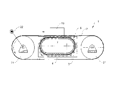
Figure 1 shows a conveying apparatus 1 with a conveying
belt as a conveying means 2 for conveying material 10,
5 in this case illustrated, by way of example, in the
form of individual entities. The conveying belt is
guided around deflecting rollers 21, of which, for
example, one is driven by a drive 22. A supporting
device 12 is arranged in a supporting region, and has a
10 roller body 5, which circulates around a supporting
body 7. The roller body 5 has circulating rollers 3,
which are spaced apart from one another by means of a
connecting body 4. The conveying means 2 moves in a
conveying direction in relation to the supporting
15 device 12. The rollers 3 here roll on the conveying
means 2 and on the supporting body V. The supporting
device 12 thus makes it possible for the conveying
means 2 to be supported with low friction and such that
it can be subjected to high loading. The conveying
material 10 illustrated symbolizes individual entities,
bulk material or living things, such as people or
animals.
In another embodiment of the invention (not
illustrated), the roller body 5 also circulates around
the deflecting rollers 21. In order for the conveying
means 2 here to be driven, it is possible for a drive
to be arranged in the return strand (that is to say in
the lower region of the conveying means 2) and to act
there only on the conveying belt or a mat-top chain 2.
The roller body 5 there runs in a region between the
drive and supporting body 7. In another embodiment of
the invention, the roller body 5 is in a number of
parts and has a plurality of adjacent connecting bodies
4 with rollers 3. The connecting bodies 4 are spaced
apart from one another by interspaces, and therefore
the drive can act on the conveying means 2, through the
interspaces, by means of one of the deflecting rollers
21.
CA 02766414 2015-05-05
16
It is preferably the case that the roller body 5,
rather than itself being driven, is moved along only
when the conveying means 2 moves. That is to say, the
roller body or the rollers or the connecting body of
the roller body are driven exclusively passively,
rather than actively.
Figure 2 shows a detail of a conveying apparatus 1 with
a mat-top chain as conveying means 2. Figure 3 shows a
detail of a conveying apparatus 1 with a mat-top chain
and a belt 6 in addition. The belt 6 safeguards the
roller body 5 against dirt, which may fall through the
mat-top chain.
Figure 4 shows a side view of a supporting body 7 with
a roller body 5 and, correspondingly, figure 5 shows a
cross section through figure 4_ A guide groove 71 for
guiding the connecting body 4 in the supporting body 7
is illustrated in addition to the elements which have
already been described.
Figure 6 shows a detail of a roller body 5, with a
longitudinal section through a roller 3_ The connecting
body 4 of the roller body 5 has openings 41, at which
are formed bearing or retaining locations 42, by means
of which the rollers 3 are mounted or retained and
guided. The bearing or retaining locations 42 may, as
illustrated, be protuberances of the connecting body 4,
which engage in correspondingly shaped notches or
apertures in the rollers 3. The apertures in the
rollers 3 may be formed, as illustrated, as through-
holes 31, that is to say that the rollers 3 are formed
as sleeves or pieces of tube. As an alternative, the
apertures may be formed merely as rotationally
symmetrical depressions at the ends of the rollers. The
depressions preferably taper inward. The rollers 3 here
are preferably formed as (plastics-material) injection
moldings. Conversely, it is possible for the rollers 3
CA 02766414 2015-05-05
17
to have projecting axial elements which can be inserted
into openings in the connecting body 4.
Figure 7 shows a plan view of a curved region of a
conveying apparatus 1 with a mat-top chain as conveying
means 2. A rectilinearly running roller body 5a and a
curve-negotiating roller body 5b are illustrated by
dashed lines beneath the conveying means 2. Figure 8
shows a plan view of a roller body 5 for a curve,
without the associated supporting body 7. In order to
be able to negotiate the curve, the connecting body 4
has bearing or retaining regions 45, in which the
rollers 3 are inserted, and connecting locations 46,
which connect the bearing or retaining regions 45. In
the example shown, the connecting locations 46 are
arranged in the center of the connecting bodies 4, but
they may also be arranged asymmetrically or all the way
to one side (in the figure, where the bearing or
retaining regions 45 butt against one another on
account of the curve: alternative site 47 for
connecting location). Figure 9 shows a lateral view of
a supporting body 7 for a curve with the roller body 5b
running around the curve. It is therefore the case
that, rather than running parallel to one another as in
the case of a rectilinearly running roller body 5a,
axes of the rollers 3 along the curve are aligned
essentially with the curve axis. The center points of
the rollers run along a curved surface.
Figure 10 shows a plurality of concentric supporting
bodies 'lb for a curve, roller bodies 5 and guide
grooves 71 and the like being omitted for reasons of
clarity. The supporting bodies 7b form circulatory
paths which are curved in relation to the curve axis
11. This makes it possible to support conveying means 2
of essentially any desired width.
Figure 11 shows a cross section through a conveying
apparatus 1 with laterally angled supporting regions,
CA 02766414 2015-05-05
18
each with dedicated supporting devices 12 with
supporting bodies 7 and roller bodies 5, in addition to
a supporting device 12 in a horizontally depicted base
region. This arrangement is particularly suitable for
supporting conveying belts for bulk material.
Figure 12 shows a variant of a roller body 5 with a
plurality of rows 51 of rollers 3 offset in relation to
one another in the axial direction (detail). The roller
body 5 forms a moving roller carpet which can circulate
around a supporting body 7 or can also roll on a level
plane, which serves as the supporting body 7. It is
also the case that a plurality of columns 52 are
present in this embodiment, wherein the rollers of a
first column 52a are spaced apart from one another in
the movement direction and are arranged, partially in
each case, between rollers of another column 52b, which
is displaced laterally (that is to say in the axial
direction) in relation to the first column 52a.
Figure 13 shows a further variant of a roller body 5,
in which the rollers 3 run in at least two, or more,
columns 52 which run parallel one beside the other, and
are not offset in relation to one another. For the sake
of clarity, openings 41 and protuberances 42 are shown
without rollers 3 inserted in rear rows of the
connecting bodies 4 of figures 12 and 13. Figure 14
shows a further variant of a roller body 5, similar to
figure 12, but with pairs of non-offset rows 51.
Figure 15 shows a roller body 5 with a connecting body
4 made of a plurality of layers 44. The individual
layers 44 are offset in relation to one another in the
longitudinal direction of the connecting body. Three
layers 44 are shown, but it is also possible for just
two, or for four or more, layers 44 to be present. To
aid clarity, the layers 44 are depicted in a separated
state; in reality, they lie loosely one upon the other
or are connected to one another. The depicted offset
CA 02766414 2015-05-05
19
between two layers involves two rollers 3, but may also
involve more.
Figure 16 shows a roller body 5 with a connecting body
4 made of a looped part. This means that a single layer
44, formed in a loop, is laid over on itself and thus
forms an at least two-layered connecting body 4.
Figure 17 shows a conveying apparatus 1 with lateral
guide elements 8. The guide elements 8 have roller
bodies 5 and supporting bodies 7, wherein the
circulatory paths of the roller bodies 5 are located in
an essentially horizontal or inclined plane, in order
for conveying material 10 to be guided or deflected
laterally. Optional belts around all the rollers 3, as
part of the roller bodies 5, have not been depicted
here. In the embodiment shown, the conveying apparatus
1 serves for bringing together a plurality of conveying
paths 9 arranged laterally in relation to one another,
or for bringing together conveying material 10 which is
transported on these conveying paths 9. A conveying
path which is relatively wide overall is thus reduced
to a narrower conveying path. The individual conveying
paths 9 may have different conveying speeds and, for
this purpose, circulate around individually rotatable
rollers.
Figure 18a shows a further embodiment of a roller 103,
which in this case is cylindrical and has a centrally
arranged annular circumferential groove 109 running all
the way around it. That is to say, the groove is
arranged concentrically in relation to the axis of
rotation of the roller. The curved (lateral) surface
100 of the roller 103, with the exception of the groove
109, is cylindrical.
Figure 18h shows a further embodiment of a roller 133,
which differs from the embodiment according to
figure 18a in that the lateral surface 161 is slightly
CA 02766414 2015-05-05
convex. That is to say, the roller 133 is barrel-
shaped. The concentric, annular circumferential grooves
109, 110 of the two embodiments are guide grooves,
which serve for guiding the rollers 103, 133 along
5 their circulatory path around the supporting body. The
groove guidance means that transverse forces, that is
to say axial forces, which otherwise act on the means
for retaining the rollers on the connecting body are
absorbed.
Figure 19 shows a perspective view of a supporting
device 112 with a roller body 105. The difference from
the supporting device 12 which is shown in figures 4-6
is that the roller body 105 of the supporting device
112 shown here is provided with rollers 133 according
to the exemplary embodiment of figure 18b.
Figure 20a shows a side view of a supporting device 112
according to figure 19.
Figure 20b shows a cross section through the supporting
device 112 according to figure 20a, taken along line
A-A. The supporting body 107 has a guide rib 162 which
runs all the way around it, as seen in the movement
direction of the rollers 133, and engages in the guide
grooves of the rollers 133. The shape of the guide rib
162, in particular the width and height thereof, is
coordinated to correspond with the cross-sectional
dimensions of the groove. That is to say, the roller
133, which is guided via the guide groove 110, has only
a small amount of lateral play, if any at all. The
guide rib 162 may be formed with or without
interruptions. The rollers 133 are retained via a
planar, flexible connecting body 104 and are guided or
mounted thereby on the supporting body 107. It is also
possible, in principle, for the groove/rib guidance to
be formed the other way round.
CA 02766414 2015-05-05
21
The additional guiding support provided by the above-
described groove/rib guidance is used preferably in the
case of arcuate guide paths, where the axes of
successive rollers, rather than being parallel to one
another as in the case of the rectilinearly running
guide path, are aligned essentially with a curve axis.
Such arcuate guide paths are illustrated, for example,
in the exemplary embodiments according to figures 7 to
10.
CA 02766414 2015-05-05
22
LIST OF DESIGNATIONS
1 Conveying apparatus 45 Bearing or retaining
2 Conveying means region
3 Roller 46 Connecting location
4 Connecting body 47 Alternative site for
Roller body connecting location
6 Belt 51 Row
7 Supporting body 52 Column
8 Guide element 71 Guide groove
9 Conveying path 100 Lateral surface
Conveying material 103 Roller
11 Curve axis 104 Connecting body
12 Supporting device 105 Roller body
21 Deflecting roller 107 Supporting body
22 Drive 109 Circumferential groove
31 Aperture 110 Circumferential groove
41 Opening 112 Supporting device
42 Protuberance 133 Roller
44 Layer 161 Lateral surface
162 Guide rib