Note : Les descriptions sont présentées dans la langue officielle dans laquelle elles ont été soumises.
CA 02767020 2011-12-29
WO 2011/003026 PCT/US2010/040827
TURBOELECTRIC COAGULATION APPARATUS
FIELD OF THE INVENTION
[0001] The present invention relates generally to water purification and, more
particularly, to purification of water using electrocoagulation.
BACKGROUND OF THE INVENTION
[0002] Rivers, canals, estuaries and other water bodies which are used as
sources of clean water in developing countries have become polluted by
indiscriminate discharge of industrial and animal waste products and by
natural
processes such as geochemical processes which have introduced dangerous
elements including arsenic into the groundwater. Wastewater generated by
increasing population, industry and other sources has become problematic in
developed countries as well.
[0003] Coagulation is an important reaction for water treatment. Ions from
heavy
metals, as an example, and colloids generally remain in solution as a result
of their
electric charge. By adding ions having opposite charges to the colloids, the
ions and
colloids can be destabilized and coagulation can be achieved by chemical or
electrical methods. In the case of chemical coagulation, a coagulant, such as
Alum
[A12(SO4)3=18H20] or ferric chloride, as examples, may be employed. However,
chemical coagulation tends to generate large volumes of sludge with
significant
bound water content.
[0004] In electrocoagulation, reactive ions may be generated in situ by
oxidation
of an effective anode material, or reactive metallic hydroxides may be
generated
within the effluent, and offers an alternative to the addition of metal salts,
polymers or
polyelectrolytes. Treatment of wastewater by electrocoagulation has been
practiced
for about 100 years and currently used in many industries. Metals, colloidal
solids
and suspended particles and oil droplets may be removed from wastewater by
agglomeration or coagulation and resultant separation from the aqueous phase.
An
electrocoagulated floc tends to contain less water, and is more readily
filterable.
[0005] Basically, an electrocoagulation reactor includes pairs of parallel
conductive metal plates, known as sacrificial electrodes which may be of the
same or
of different materials. When connected to an external source of electrical
power, the
1
CA 02767020 2011-12-29
WO 2011/003026 PCT/US2010/040827
anode material will electrochemically corrode, while the cathode will be
subject to
passivation. Metals such as aluminum and iron are commonly used to generate
ions
in the water which, as stated hereinabove, remove the contaminants by chemical
reaction and precipitation, or by causing colloidal materials to coalesce
making these
species less soluble.
[0006] It is known that electrodes in electrocoagulation reactors often
experience
scaling or other metal coating processes over time which diminish their
effectiveness
as electrodes, thereby necessitating the use of readily removable and
resurfaceable
structures.
[0007] A Tesla pump includes a plurality of parallel, flat rigid disks having
a
suitable diameter and keyed to a shaft driven by a motor such that the disks
may
rotate together as the shaft is rotated. Fluid is caused to enter the pump in
the
vicinity of the shaft, and liquid adhesion and viscosity directs the fluid
toward the
periphery as the disks are rotated, thereby imparting energy thereto as the
fluid exits
the apparatus.
SUMMARY OF THE INVENTION
[0008] Accordingly, it is an object of the present invention to provide an
electrocoagulation apparatus wherein the electrode surfaces are cleaned of
scale
and other deposits during use thereof.
[0009] Additional non-limiting objects, advantages and novel features of the
invention will be set forth in part in the description which follows, and in
part will
become apparent to those skilled in the art upon examination of the following
or may
be learned by practice of the invention. The objects and advantages of the
invention
may be realized and attained by means of the instrumentalities and
combinations
particularly pointed out in the appended claims.
[0010] To achieve the foregoing and other objects, and in accordance with the
purposes of the present invention, as embodied and broadly described herein,
the
apparatus for removing contaminants from water, hereof, includes in
combination: a
container for holding the water; at least one rotatable planar electrode
having an
axis; a spindle having an axis collinear with the axis of each of the at least
one
rotatable electrodes, the at least one rotatable electrode being attached to
the
spindle; at least one planar stationary electrode having an opening therein
effective
for permitting the spindle to pass therethrough disposed in the proximity of
and
2
CA 02767020 2011-12-29
WO 2011/003026 PCT/US2010/040827
parallel to the plane of the at least one rotatable electrode, and forming a
volume
therebetween, the at least one rotatable electrode and the at least one
stationary
electrode being disposed in the water; a source of current in electrical
contact with
the at least one stationary electrode and the at least one rotatable electrode
effective
for causing electrocoagulation of the contaminants in the water; and means for
rotating the spindle about the axis thereof at a chosen angular velocity such
that the
contaminated water is caused to pass through the volume.
[0011] In another aspect of the invention, and in accordance with its objects
and
purposes, the method for removing contaminants from water, hereof, includes
the
steps of: providing at least one planar rotatable electrode capable of being
rotated
about an axis of rotation by a spindle collinear with this axis, and at least
one planar
stationary electrode disposed in the proximity of and parallel to the plane of
the at
least one rotatable electrode and forming a volume therebetween, the spindle
passing through a first opening in the at least one stationary electrode;
contacting
the at least one rotatable electrode and the at least one stationary electrode
with the
contaminated water; rotating the spindle at a chosen angular velocity such
that the
contaminated water is caused to pass through the volume; and applying a
current
between the at least one stationary electrode and the at least one rotating
circular
electrode effective for causing electrocoagulation of the contaminants in the
water.
[0012] Benefits and advantages of the present invention include, but are not
limited to, providing an electrocoagulation reactor in which the electrodes
are
cleaned as the apparatus removes unwanted contaminants from the water. Another
benefit of the present rotating plate apparatus is that a smaller volume
apparatus is
effective for treating the same volume of water as a larger stationary plate
apparatus,
due to multiple exposures of the water to the rotating electrodes.
BRIEF DESCRIPTION OF THE DRAWINGS
[0013] The accompanying drawings, which are incorporated in and form a part of
the specification, illustrate the embodiments of the present invention and,
together
with the description, serve to explain the principles of the invention. In the
drawings:
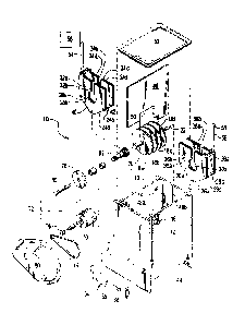
[0014] FIGURE 1A is a schematic representation of an exploded view of an
embodiment of the present electrocoagulation apparatus, FIG. 1B shows a
schematic representation of a top view thereof, and FIG. 1C illustrates a
schematic
representation of a perspective view of the assembled apparatus.
3
CA 02767020 2011-12-29
WO 2011/003026 PCT/US2010/040827
[0015] FIGURE 2A is a schematic representation of perspective view of another
embodiment of the electrocoagulation apparatus illustrating water entering and
exiting the apparatus perpendicular to the electrode structure thereof; FIG.
2B is a
schematic representation of the interior of the top lid showing the stationary
electrodes and illustrating the expected flow of water through and around the
electrodes as a result of the pumping action of the apparatus when the
rotatable
electrodes are placed in motion; and FIG. 2C is a schematic representation of
a top
view of the embodiment of the electrocoagulation apparatus shown in FIG. 2A
hereof, again illustrating the expected water flow through and around the
electrodes
as a result of the pumping action of the apparatus.
[0016] FIGURE 3A is a schematic representation of a side view of a vertical,
hollow shaft embodiment for rotating the circular electrodes illustrating the
transportation of water through the shaft as part of the pumping action of the
apparatus, while FIG. 3B is a schematic representation of a perspective view
of the
apparatus shown in FIG. 3A hereof further illustrating peripheral slots in the
stationary electrode for permitting water to flow through the electrode.
[0017] FIGURE 4 is a schematic representation of the present
electrocoagulation
apparatus adapted for processing water from an available source such as a
lake,
well, mine, or ship bilge, as examples.
DETAILED DESCRIPTION OF THE INVENTION
[0018] Briefly, the present invention includes an apparatus and method for
removing contaminant species from water by electrocoagulation. The water is
recirculated by at least one flat rigid disk having a suitable diameter and
keyed to a
motor driven shaft such that the disk may rotate as the shaft is rotated, and
at least
one flat, rigid stationary plate spaced apart and parallel to the disk, which
together
function as a fluid pump. Fluid is caused to enter through at least one
opening in the
stationary plate in the vicinity of the shaft, and liquid adhesion and
viscosity directs
the fluid toward the periphery of the disk/plate assembly as the disk is
rotated,
thereby imparting energy thereto as the fluid departs the outer periphery of
the
rotating disk. The fluid then recirculates back to the opening near the shaft
where it
again enters the volume between the stationary plate and the rotating disk
such that
it can be again accelerated by the rotating disk back to the periphery.
Additional flat
rigid disks keyed to the motor driven shaft such that they rotate together as
the shaft
4
CA 02767020 2011-12-29
WO 2011/003026 PCT/US2010/040827
is rotated, and additional stationary plates disposed in an alternating,
plate/disk/plate
arrangement, as an example, may be added. The apparatus may be located in a
reaction tank or reactor, and the flow rate of the water into and out of the
reactor and
the speed of the rotation of the disks determine the number of repetitions of
the
water through the pump.
[0019] An electric current is caused to flow between each pair of rotating and
stationary electrodes, thereby producing electrocoagulation of the
contaminants in
the water flowing therebetween. The pumping action continuously re-exposes the
water to the electrocoagulation process which enables a smaller reactor to be
employed for a given volume of water to be processed. An insoluble abrasive
material introduced into the water removes scale from the electrodes as the
water is
pumped thereby.
[0020] The electrocoagulated materials may be separated from the treated water
by filtration or by permitting the treated water to stand for a chosen period.
[0021] Reference will now be made in detail to the present embodiments of the
invention, examples of which are illustrated in the accompanying drawings. In
the
FIGURES, similar structure will be identified using identical reference
characters.
Turning now to FIG. 1A, a schematic representation of an exploded view of an
embodiment of the present electrocoagulation apparatus, 10, is shown.
Container,
12, having internal volume, 13, has inlet, 14, and outlet, 16, ports for
introducing
contaminated water to and permitting treated water to exit from container 12,
respectively. Planar, spaced apart, circular, electrically conducting
electrodes, 18a -
18d, disposed parallel to each other, and connected by electrically conducting
shaft
or spindle, 20, capable of rotation about longitudinal axis, 22, and
stationary planar,
spaced-apart, electrically conducting electrodes, 24a,b, 24c,d, 26a,b, and
26c,d,
disposed parallel to each other, are shown as disposed in pairs of electrodes
adapted for receiving circular electrodes 18a - 18d, respectively,
therebetween. It
should be mentioned that although electrodes 18 are shown as being circular in
the
FIGURES, other shapes having an axis of rotation may be contemplated.
Electrodes
18 may be constructed using reactive metals such as aluminum, iron, calcium,
and
magnesium, as examples, while electrodes 24 and 26 may be constructed from an
inert conducting material such as stainless steel, titanium, platinum, and
graphite, as
examples. Alternatively, the stationary electrodes may be constructed using
reactive
metals, while the rotating electrodes may be fabricated using inert conducting
CA 02767020 2011-12-29
WO 2011/003026 PCT/US2010/040827
materials. As may be observed in EXAMPLE 2, hereof, electrodes fabricated from
different reactive metals may be employed on the same shaft. Openings, 28, and
30, shown in stationary electrodes 24a and 24b and 26a and 26b, respectively,
as
examples, permit spindle 20 to pass therethrough without coming in contact
therewith. Clearly, electrode pairs 24c, 24d, 26c, and 26d, have similar
openings
(not shown in FIG. 1A) in order to permit spindle 20 to pass therethrough.
Additional
openings, 32a,b and 36a,b, in plates 24a,b and 26a,b, respectively, and 34a,b
and
38a,b in plates 24c,d and 26c,d, respectively are contiguous with openings
28a,b,
30a,b, respectively, and those openings not shown in FIG. 1A, and permit water
to
flow more freely into the volumes formed between circular electrodes 18a - 18d
and
stationary electrodes 24a - 26d. Stationary electrodes 24 and 26 may have
curved
or angled bases, 40 and 42, as examples, to better fit the inside shape (not
shown in
FIG. 1A) of the bottom portion, 44, of container 12. This feature, along with
the use
of baffle, 46, adapted to fit into grooves, 48a and 48b, in container 12, and
having
indentation, 50, to enable the baffle to more closely fit around stationary
electrodes
24 and 26, reduce the quantity of water traveling between fluid input 14 and
output
16 of container 12 without passing through the volumes formed between the
circular
and stationary electrodes, in this specific example. Cover, 52, prevents
materials
from exiting container 12 as a result of frothing, as an example.
[0022] Electrically conducting connectors, 54, and 56, permit a voltage from
direct
current source, 58, to be applied to stationary electrodes 24 and 26,
respectively.
Electrically conducting drive shaft components, 60, and, 62, which when
connected
to spindle 20, enable the rotation of circular electrodes 18. The assembled
drive
shaft components, in cooperation with brush housing, 64, brush, 66, or other
electrically conducting slip ring mechanism and end cap, 68, permit current
flow
between the electrodes through the water in volume 13. Current source 58 may
be a
constant current source or other current waveform effective for promoting
coagulation. End cap 68 may be grounded, or otherwise provide a current return
to
source 58.
[0023] Electric motor, 70, powered by electric power source, 72, drives belt,
74,
using first pulley, 76, attached thereto, the combination driving second
pulley, 78,
attached to drive shaft component 60 which turns electrodes 18 through spindle
20.
Accompanying bushings and shaft seals provide smooth rotation of the drive
shaft
and prevention of water leakage from container 12. Power source 72 may include
6
CA 02767020 2011-12-29
WO 2011/003026 PCT/US2010/040827
batteries, solar cells, and appropriate line voltage. Cover, 80, provides
protection for
users from belt 74. It is anticipated that other driving apparatus may be
utilized to
turn shaft component 60 such as a stepping motor for directly turning shaft
60, as an
example.
[0024] FIGURE 1 B shows a top view of the embodiment of the electrocoagulation
apparatus illustrated in FIG. 1A hereof. Additionally shown are water pump,
82, for
flowing water through volume 13 at a chosen rate, thereby generating a
selected
dwell time for the water in the electrocoagulation environment, and volumes,
84, and
86, between rotating circular electrode 18a and stationary electrodes 24a and
24b,
respectively, as examples, through which the rotating electrodes force the
water to
be treated.
[0025] FIGURE IC illustrates a perspective view of the assembled apparatus
illustrated in FIG. 1A hereof, showing a slightly different configuration for
motor 70, a
curved lower interior portion, 88, for container 12, and an electrical
connection, 90,
for cover plate 68.
[0026] In use, electrocoagulation apparatus 10, is filled with water to be
treated
such that the electrodes are in contact therewith. Generally, the electrodes
are
submerged in the water, although complete immersion is not required. An amount
of
insoluble abrasive material effective for keeping the electrodes free of scale
and
other coatings may be introduced into container 12 if the raw water sample to
be
treated contains inadequate abrasive material suspended therein. The abrasive
material may be chosen from sand, glass beads, ground glass, or garnet, and
mixtures thereof, although any abrasive material may be effective. The
rotation
speed of the spindle is chosen such that the abrasive material is effectively
circulated for depassivation of the electrodes, and such that the apparatus
circulates
a chosen quantity of water. Rotation speeds between 100 and 1000 RPM are
expected to be effective. Typical flow rates for the water through the
apparatus with
the above-described components are between about 1 gal./min. and about 5
gal./min., depending on the level of contamination of the liquid. Amounts and
particle sizes of the abrasive materials are chosen such that the flow rate of
the
pumped water maintains an effective quantity of particles in suspension and
circulating between the plates. Abrasive materials may be removed from the
output
stream by allowing these materials to settle, as an example, or by using a
filtration
7
CA 02767020 2011-12-29
WO 2011/003026 PCT/US2010/040827
process. Collected materials may subsequently be returned to container 12 for
reuse as is illustrated in reference character, 117, in FIG. 4 hereof.
[0027] It has been found that the efficiency of electrocoagulation is related
to the
conductivity of the water. For a constant current density, the applied voltage
may
change from 6 V to as high as 70 V during the electrocoagulation process.
Adding
small amounts of table salt have been observed to increase the speed of the
electrocoagulation process and decrease the power requirements. It has also
been
found that the consumption of the electrodes by ionization of the metal is a
direct
function of the current density. Since the conductivity of the water cannot
readily be
controlled, and may change over time, a constant current generator has been
employed which changes the voltage across the electrodes to maintain the
current at
a constant value.
[0028] Electrodes having between about 2 in. and about 120 in. diameter,
between about 1/32 in. and about 1 in. thickness and spaced-apart between
about
1/8 in. and about 0.5 in. are expected to be effective for the
electrocoagulation
process of the present invention. The dimensions of the apparatus, the number
of
plates and the required current are determined by the volume of water to be
treated
per minute. Embodiments of the apparatus of the present invention are
anticipated
to be effective for processing water volumes between a few quarts per minute
and
thousands of gallons per minute.
[0029] FIGURE 2A is a schematic representation of perspective view of another
embodiment of the electrocoagulation apparatus illustrating water entering and
exiting the apparatus through tubes 14 and 16, respectively, perpendicular to
the
electrode structure thereof shown as two stationary electrodes 24a and 24b,
and
rotating electrode 18a. Electrodes 24a and 24b are each illustrated as having
two
parts which are joined when lid 52 is in place, but may be fabricated as a
single
electrode. Water sealing gaskets for surfaces, 92a, and, 92b, and shaft seals,
94a,
and 94b, for providing a water seal between rotating shaft 20 and container 12
and
top portion 52, have not been shown, nor have the electrical connections to
the
electrodes, in order to simplify FIG. 2A. Apertures 28a and 28b in stationary
electrodes 24a and 24b are sized to permit water to readily flow into the
region
between the stationary electrodes and the rotating electrode 18a as well as
between
the electrodes and the inner surfaces of container 12 and cover 52 as a result
of the
pumping action when shaft 20 rotates electrode 18a, while FIG. 2B is a
schematic
8
CA 02767020 2011-12-29
WO 2011/003026 PCT/US2010/040827
representation of the interior of lid 52 showing the stationary electrodes and
illustrating the expected direction of the flow of water, 96, through and
around the
electrodes as a result of the pumping action of the electrodes. FIGURE 2C is a
schematic representation of a top view of the embodiment of the
electrocoagulation
apparatus shown in FIG. 2A hereof, again illustrating the expected water flow
through and around the electrodes as a result of the pumping action of the
rotating
electrodes.
[0030] FIGURE 3A is a schematic representation of a side view of
electrocoagualation apparatus 10, wherein shaft 20 is oriented vertically and
has
hollow portion, 98, and open end, 100, for permitting water 96 to enter the
shaft, and
exit holes, 102a - 102e, for permiting the water to exit the shaft, when
electrodes
18a - 18b are placed in rotary motion. FIGURE 3B is a schematic representation
of
a perspective view of the apparatus shown in FIG. 3A hereof further
illustrating
peripheral slots, 104, in stationary electrode 24a for permitting water 96 to
flow
through the electrode, and a vertical orientation of the axis of rotation.
[0031] FIGURE 4 is a schematic representation of the present
electrocoagulation
apparatus adapted for processing water from an available source, 112, such as
a
lake, well, mine, or ship bilge, as examples. The water from the source may be
prefiltered using filter, 114, and introduced into electrocoagulator 10 using
pump 82
for controlling the water flow rate and, hence the dwell time in the
electrocoagulator.
The water may be further filtered using coarse prefilter, 116. Abrasive
exiting
electrocoagulator 10 along with the treated water may be removed by separator,
117, and returned to coagulator 10. Treated water exiting coagulator 10 may be
directed through batch valve, 118, to one or more clarifier tanks, 120, 122,
where the
electrocoagulated contaminants are separated by gravity from the water and
directed
through valves, 124, and 126, respectively, to sludge disposal location, 128.
Purified
water may be directed out of tanks 120 and 122 using valve 130, and may be
further
filtered using post filter, 132, and stored in tank, 134. Pump, 136, may be
used to
direct the water from tank 134 through ozonizer, 138, if additional
purification is
required, and dispensed using valve, 140. Whereas, FIG. 4 illustrates the
separation
of the electrocoagulated contaminants by batch processing, it is equally
effective to
use a continouous settling process or a continuous filtration process.
[0032] Having generally described the invention, the following EXAMPLES
provide additional details:
9
CA 02767020 2011-12-29
WO 2011/003026 PCT/US2010/040827
EXAMPLE 1
[0033] A mixture of 200 ml of coal dust and 3.7 L of water was added to a 1
gal.
container having a similar configuration to that illustrated in FIGS. 3A and
3B, hereof,
except that one aluminum rotating electrode and two aluminum stationary
electrodes
were employed. A voltage of 12 V was applied for 5 min. between the stationary
and
rotating electrodes, the rotating electrodes having 3" diameter, 1/16 in.
thickness,
spaced apart from the stationary electrodes by 1/4 in., and rotated at 600
rpm. The
stationary electrodes were 1/16 in. thick. A current of about 5 A flowed
between the
electrodes. No abrasive or salt was added to the water. After coagulation, the
processed water was allowed to stand for 5 min. and the turbidity was observed
to
change from high to low using a commercially available turbidity meter.
EXAMPLE 2
[0034] A surrogate water sample having greater than 200 ppb of arsenic as As3+
was flowed into a 1.25 gal. electrocoagulation cell similar to that
illustrated in FIGS.
3A and 3B, hereof, at about 20 L/h having both iron and aluminum 3 in.
diameter
electrodes spaced 0.250 in. apart, on the same spindle rotated at about 900
rpm,
and separated by an aluminum stationary electrode equally distant
therebetween.
Playground sand was used as the abrasive, the voltage between the rotating and
stationary electrodes was 12 V and the current flow therebetween was about 5
A.
After treatment, the water exiting the container was allowed to settle for 30
min., and
then decanted without additional filtering. The arsenic concentration was
found to be
below the detectable limit of the testing apparatus employed, which was
estimated to
be less than 10 ppb. Analysis of the floc indicated an arsenic concentration
of
greater than 300 ppb. It is believed by the present inventors that the iron as
Fe+++
reacted with the arsenic and that the aluminum was effective in removing both
the
iron and the reacted arsenic.
[0035] The foregoing description of the invention has been presented for
purposes of illustration and description and is not intended to be exhaustive
or to
limit the invention to the precise form disclosed, and obviously many
modifications
and variations are possible in light of the above teaching. The embodiments
were
chosen and described in order to best explain the principles of the invention
and its
practical application to thereby enable others skilled in the art to best
utilize the
invention in various embodiments and with various modifications as are suited
to the
CA 02767020 2011-12-29
WO 2011/003026 PCT/US2010/040827
particular use contemplated. It is intended that the scope of the invention be
defined
by the claims appended hereto.
11