Note : Les descriptions sont présentées dans la langue officielle dans laquelle elles ont été soumises.
CA 02767749 2012-01-10
WO 2011/005369 PCT/US2010/035986
CONTROL VALVE HAVING PRESSURE BOUNDARY INTEGRITY
DIAGNOSTIC CAPABILITIES, METHOD OF MAKING THE CONTROL
VALVE, AND METHOD OF USING THE CONTROL VALVE
FIELD OF THE INVENTION
[0001] The present disclosure generally relates to a control valve having
pressure
boundary integrity diagnostic capabilities, a method of manufacturing the
control
valve, and a method of using the control valve.
BACKGROUND OF THE INVENTION
[0002] A major safety concern for process control valves is the loss of metal
and
wall thickness in the body of the valve. The high fluid velocities encountered
by
control valves can contribute to and accelerate wear caused by the process
fluid. As a
result, corrosion due to loss of protective coatings and metal loss due to
cavitation are
accelerated. Predicting the remaining life of a valve body or the need for
maintenance
by regularly testing the valve body for loss of metal and decrease in wall
thickness is
particularly troublesome as compared to pipes because the irregular shape of
the valve
body does not allow for use of conventional testing techniques such as
ultrasonic
testing.
[0003] Where the pressure differential is large, the high velocity created
within the
device can be detrimental. For example, in liquid systems the resulting high
velocities can produce cavitation. This occurs when the pressure at the Vena
Contracta falls below the vapor pressure of the liquid, producing vapor
bubbles which
subsequently collapse when the bubbles enter the relatively higher pressure
region
downstream. The collapse of these bubbles within the device may cause physical
damage to the parts through erosion, which may shorten the useful life of the
device.
SUMMARY OF THE INVENTION
[0004] In accordance with an embodiment of the invention, a method of
manufacturing a control valve having pressure boundary diagnostic capabilities
includes choosing a control valve having a valve body, determining a velocity
profile
within the control valve, choosing an area of the velocity profile, choosing a
point on
an exterior of the valve body at or adjacent to the area, forming a pad on the
surface
of the exterior of the valve body overlying the point, applying a testing
device to the
1
CA 02767749 2012-01-10
WO 2011/005369 PCT/US2010/035986
pad, and measuring a reference thickness of a wall of the valve body through
the pad
using the testing device.
[0005] In accordance with another embodiment of the invention, a method of
manufacturing a control valve having pressure boundary integrity diagnostic
capabilities includes choosing a control valve having a valve body,
determining a
velocity profile, choosing an area of the velocity profile, choosing a first
point on an
interior of the valve body at or adjacent to the area of high velocity,
forming a boss on
the interior surface overlying the point, forming a pad on the surface of the
exterior of
the valve body overlying at least a portion of the boss, applying a testing
device to the
pad, and measuring a reference thickness of a wall of the valve body,
including the
boss, through the pad using the testing device.
[0006] In accordance with yet another embodiment of the invention, a control
valve
having pressure boundary integrity diagnostic capabilities includes a valve
body
having a fluid inlet, a fluid outlet, a connecting valve body passageway, the
valve
body having an identified velocity profile, a valve seat mounted in the valve
body
passageway, a valve operating member adapted to cooperate with the valve seat
to
control the flow of fluid through the valve body passageway, a point chosen an
exterior of the valve body at or adjacent to an area of the identified
velocity profile,
and a pad formed on the exterior of the valve body overlying the point.
[0007] In accordance with another embodiment of the invention, a control valve
having pressure boundary integrity diagnostic capabilities includes a valve
body
having a fluid inlet, a fluid outlet, a connecting valve body passageway, the
valve
body having an identified velocity profile, a valve seat mounted in the valve
body
passageway, a valve operating member adapted to cooperate with the valve seat
to
control the flow of fluid through the valve body passageway, a first point
chosen on
an internal surface of the valve body at or adjacent to an area of the
identified velocity
profile, a boss formed on the internal surface of the valve body overlying the
first
point, and a pad formed on the external surface of the valve body overlying at
least a
= portion of the boss.
[0008] In accordance with an embodiment of the invention, a method of
diagnosing
pressure boundary integrity of a control valve includes providing a control
valve .
having a valve body, identifying a velocity profile within the valve body,
choosing an
2
CA 02767749 2012-01-10
WO 2011/005369 PCT/US2010/035986
area of the velocity profile, choosing a point on an exterior of the valve
body at or
adjacent to the area, forming a pad on the exterior surface overlying the
point,
applying a testing device to the pad, measuring a reference thickness of a
valve body
wall located through the pad, applying a testing device to the pad at a time
subsequent
to the measurement of the reference thickness, measuring a first thickness of
the valve
body wall through the pad, and comparing the reference thickness to the first
thickness to determine the pressure boundary integrity of the control valve.
BRIEF DESCRIPTION OF THE DRAWINGS
[0009] For a more complete understanding of the disclosure, reference should
be
made to the following detailed description and accompanying drawings.
[0010] Figure 1 is a cross-sectional view of a control valve having a pad in
accordance with an embodiment of the invention;
[0011] Figure 2 is a partial view of the control valve of Figure 1, showing
the pad;
[0012] Figure 3 is a cross-sectional view of a control valve having a pad and
a boss
in accordance with an embodiment of the invention; and
[0013] Figure 4 is a partial view of the control valve of Figure 3, showing
the pad
and boss.
[0014] Figure 5 is a partial view of a control valve having. a pad and a
testing
device applied to the pad in accordance with an embodiment of the invention.
[0015] Figure 6 is a partial view of a control valve having a pad with a
handheld
testing device being applied to the pad in accordance with an embodiment of
the
invention.
[0016] Figure 7 is a partial view of a control valve having a pad and a
calibration
lug in accordance with an embodiment of the invention.
[0017] Figure 8 is a cross-sectional view of a control valve having a pad and
a
calibration pad in accordance with an embodiment of the invention.
DETAILED DESCRIPTION
[0018] A control valve having pressure boundary diagnostic capabilities in
accordance with the present invention includes a pad formed on an exterior of
a valve
3
CA 02767749 2012-01-10
WO 2011/005369 PCT/US2010/035986
body adjacent an area having an identified velocity profile. The pad can be
formed on
the exterior of any known valve type. For example, cage-type valves, globe
valves,
and rotary valves can be selected for forming a control valve having pressure
boundary diagnostic capabilities.
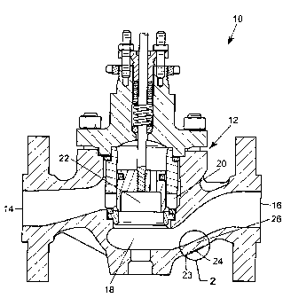
[0019] Referring to Figure 1, in general, a control valve 10 includes valve
body 12
having a fluid inlet 14, a fluid outlet 16, and a connecting valve body
passageway 18
disposed between the fluid inlet 14 and fluid outlet 16. The valve 10 further
includes
a valve seat 20 mounted in the valve body passageway 18, and a valve operating
member 22 adapted to cooperate with the valve seat 20 to control the flow of
fluid
through the valve body passageway 18. A velocity profile of fluid flowing
through
the control valve 10 can be determined by any known conventional method, for
example, using computational fluid dynamics. Areas of the velocity profile can
be
chosen for analysis. For example, the area or areas of the velocity profile
chosen can
be an area or areas of highest fluid velocity. For example, velocities in
natural gas
production with high pressure drops may be as high as sonic velocity and may
include
entrained sand and hydrocarbon liquid droplets. Similarly, steam and other
compressible fluids may achieve sonic velocity when there is a high pressure
drop.
These areas of highest fluid velocities can cause a loss of metal and valve
body wall
=
26 thickness.
[0020] Referring to Figures 1 and 2, the control valve 10 includes a point 23
chosen
on the exterior of the valve body 12 at or adjacent to the chosen area of the
velocity
profile. The point 23 can be chosen, for example, to be spaced about 0 inches
to
about 2 inches away from the chosen area of the velocity profile.
Alternatively, the
point 23 can be chosen to overly the chosen area of the velocity profile.
[0021] The control valve 10 further includes a pad 24 on the exterior of the
valve
body 12 overlying the point 23. For example, the pad 24 can be formed to be
overlying the point 23 and to be at or adjacent the chosen area of the
velocity profile.
A control valve 10 having multiple chosen areas can include a point 23 chosen
at or
adjacent to each of the chosen areas, and multiple pads formed overlying each
of the
points 23.
= [0022] The pad 24 can be formed, for example, during formation of the
valve body
12. For example, a flat surface can be milled into the valve body 12 to form
the pad
4
CA 02767749 2012-01-10
WO 2011/005369 PCT/US2010/035986
24. Alternatively, the pad 24 can be formed after formation of the valve body
12. For
example, the pad 24 can be a raised surface formed on or attached to the
exterior of
the valve body 12 and then machined flat.
[0023] The pad 24 can be formed, for example, to be substantially parallel to
the
internal surface of the valve body 12. For example, the pad 24 can be formed
to be
parallel to the internal surface of the valve body 12 within a range of about
0 to about
150. Preferably, the pad 24 is formed to be parallel to the internal surface
of the valve
body 12 with an offset of less than about 5 . The pad 24 can be formed to have
a flat
exterior surface. The pad 24 can have any suitable shape. For example, the pad
24
can be substantially rectangular or circular. The pad 24 can have a diameter
in a
range of about 1 mm to about 50 mm. Preferably, the pad 24 has a diameter of
at
least about 25 mm. The pad 24 can have a height in a range of about 1 mm to
about
mm.
[0024] The flat surface of the pad 24 provides a suitable surface for use of
testing
devices, such as ultrasonic testing devices. A reference thickness of the
valve body
wall 26 located at or adjacent to the pad 24 can be measured, for example, by
applying a testing device to the pad 24 to measure the thickness of the valve
body
wall 26. For example, an ultrasonic transducer can be used to measure the
reference
thickness of the valve body wall 26. The reference thickness represents the
thickness
of the wall at to, which can be prior to a first use of the control valve 10
or prior to
continued use of the control valve 10. The pad 24 can be marked with the
reference
thickness. The pad 24 can be marked using any known methods. For example, the
reference thickness can be etched onto the pad 24 or stamped onto the pad 24.
The
pad 24 can be further marked with an alignment marking to allow for consistent
alignment of the testing device when making subsequent thickness measurements,
as
will be described in more detail below. The alignment markings can be, for
example,
an "X".
[0025] Referring to Figures 3 and 4, the control valve 10 can further include
a point
27 chosen on an interior surface of the valve body 12 at or adjacent to the
pad 24
and/or the chosen area of the velocity profile. The point 27 can be, for
example,
spaced about 0 inches to about 2 inches from the chosen area and/or the pad
24.
= =
5
CA 02767749 2012-01-10
WO 2011/005369 PCT/US2010/035986
[0026] The control valve 10 can also include a boss 28 formed on the interior
surface of the valve body 12 overlying the point 27 at or adjacent to the
chosen area
of the velocity profile. The boss 28 can be formed across from and overlapping
with
at least a portion of the pad 24 formed on the exterior of the valve body 12.
When
more than one area of the velocity profile is chosen for analysis, a point 27
can be
formed at or adjacent each of the chosen areas and a boss 28 can be formed
overlying
each of the points 27.
[0027] The boss 28 can be a raised internal surface of the valve body 12
relative to
the surrounding valve body wall 26, which can provide an accelerated wear
surface
and a more conservative wear measurement. The boss 28 can be formed, for
example, across from the pad 24 on the interior surface of the valve body 12.
The
boss 28 includes a first surface disposed at or adjacent to the interior of
the valve body
12 and a second surface disposed in the valve body passageway 18. The second
surface of the boss 28 can be oriented parallel to the surface of the pad 24
within a
range of about 00 to about 15 . Preferably, the pad 24 is formed to be
parallel to the
internal surface of the valve body 12 with an offset of less than about 5 .
The boss 28
can be flat. The boss 28 can have a thickness in a range of about 1 mm to
about 20
mm. The thickness of the valve body wall 26 including the boss 28 can be
measured
using a testing device, such as an ultrasonic transducer, to determine a
reference
thickness. The reference thickness, including the pad 24 and the boss 28 can
be in a
range of about 10 mm to about 150 mm. The reference thickness including the
boss
28 can be marked on the pad 24. The reference thickness can be marked, for
example, by etching or stamping the pad 24.
[0028] The boss 28 can be formed of a material that wears at a rate greater
than the
wear rate of the valve body 12 to provide early warning of internal wear.
Alternatively, the boss 28 can be formed of a material that is substantially
the same as
the interior of the valve body 12. The boss 28 can formed on the interior of
the valve
body 12 during formation of the valve body 12. For example, the boss 28 can be
cast
with the casting of the valve body 12. Alternatively, the boss can be attached
to the
inner surface of the valve body 12 after formation of the valve body 12. For
example,
the boss can be formed by weld deposition.
[0029] Referring to Figure 5, the valve 10 can further include, for example, a
testing device 30 operatively coupled to the exterior of the valve body 12,
with at least
6
CA 02767749 2012-01-10
WO 2011/005369 PCT/US2010/035986
a portion of the testing device 30 overlying at least a portion of the pad 24.
The
testing device 30 can be removably or permanently coupled to the valve body 12
at
the pad 24. The testing device 30 can include, for example, a communication
link 32.
The communication link 32 can be connected to the testing device 30 through a
wired
or wireless connection. The communication link 32 can be operatively coupled
to the
valve body 12 and/or the testing device 30.
[0030] Referring to Figure 6, a handheld testing device 36 having, for
example, a
communication link 38 operatively coupled to the testing device 36 can be
applied
and/or removably coupled to the exterior of the valve body 12, with at least a
portion
of the handheld testing device 36 overlying at least a portion of the pad 24.
[0031] Referring to Figures 7 and 8, the valve 10 can further include a
calibration
device formed on exterior surface of the valve body 12. Referring to Figure 8,
the
calibration device can be, for example, a calibration pad 42 formed on the
exterior
surface of the valve body 12. The calibration pad 42 at least partially
overlies a
calibration area of the velocity profile. The calibration area can be
selected, for
example, to be an area of the velocity profile having a non-erosive flow. The
thickness of the valve body wall at the calibration pad 42 is known. A testing
device
can be calibrated by applying the testing device to the calibration pad 42 and
Measuring a thickness of the valve body wall through the calibration pad 42.
The
testing device can be adjusted as necessary based on the difference between
reading
from the testing device and the known thickness of the valve body wall at the
calibration pad 42. The testing device can be calibrated, for example, prior
to
measuring the sample thickness of the valve body wall 26 through the pad 24.
The
testing device can be further calibrated, as needed, during subsequent
measurement of
the valve body wall 26 thickness. The calibration pad 42 can be formed, for
example,
= in the same manner as the pad 24.
[0032] Referring to Figure 8, the calibration device can be, for example, a
calibration lug 40 can be formed on the exterior of the valve body 12. The
calibration
lug 40 can be located in any location of the valve body 12. Preferably, the
calibration
lug 40 is located so as not interfere with testing of the valve body wall
thickness
through the pad 24. The calibration lug 40 can outwardly project from the
exterior
surface of the valve body 12 and have a known thickness. A testing device can
be
calibrated by applying the testing device to the calibration lug 40 and
measuring the
7
CA 02767749 2012-01-10
WO 2011/005369 PCT/US2010/035986
thickness of the lug. The testing device can be adjusted as needed based on
the
difference between the reading from the testing device and the known thickness
of the
calibration lug 40. The calibration lug 40 can formed on the exterior of the
valve
body 12 during formation of the valve body 12. For example, the calibration
lug 40
can be cast with the casting of the valve body 12. Alternatively, the
calibration lug 40
can be attached to the exterior of the valve body 12 after formation of the
valve body
12. For example, the calibration lug 40 can be formed by weld deposition.
[0033] To diagnose the pressure boundary integrity of the control valve 10,
the
thickness of the valve body wall 26 (and the boss 28 when used) through the
pad 24 is
measured at a time t1 subsequent to the measurement of the reference
thickness, which
can be after the valve 10 has been in use for a predetermined amount of time.
The
thickness of the valve body wall 26 is again measured by applying a testing
device,
such as an ultrasonic transducer, to the pad 24 and measuring a first
thickness through
the pad 24. The first thickness is compared to the reference thickness to
determine the
pressure boundary integrity of the control valve 10. The change in thickness
(first
thickness - reference thickness) is indicative of the absolute material loss
of the wall
as a result of fluid flow at or adjacent to the chosen area. The thickness of
the valve
body wall 26 can be measured at subsequent times t2, t3, t4, etc., and each
measurement can be compared to each other and the reference thickness to
provide a
measurement of the absolute material loss over time. These measurements can
also
be used to determine the rate of material loss (the change in thickness/the
change in
time) of the valve body wall 26, which can be used to predict the remaining
life of the
control valve 10 and/or the need for maintenance.
[0034] When an internal boss 28 is used, the first thickness is a measure of
the
thickness of the valve body wall 26 and at least a portion of the boss 28. The
first
thickness is measured as described above, by applying a testing device to the
pad 24
and measuring the thickness through the pad 24. In this case, the first
thickness can
represent the wear of the boss 28 alone to provide a more conservative measure
of
wear. When the boss 28 is made of a material that wears faster than the valve
body
12, an accelerated wear surface is provided by the boss 28. The increased
thickness
of the valve body wall 26 provided by the boss 28 can be used to.build in an
=
= automatic safety range into the valve body 12 design, as the wear of the
boss 28 can
be detected prior to significant wear of the valve body wall 26.
8