Sélection de la langue

Search

Sommaire du brevet 2768781 

Énoncé de désistement de responsabilité concernant l'information provenant de tiers

Une partie des informations de ce site Web a été fournie par des sources externes. Le gouvernement du Canada n'assume aucune responsabilité concernant la précision, l'actualité ou la fiabilité des informations fournies par les sources externes. Les utilisateurs qui désirent employer cette information devraient consulter directement la source des informations. Le contenu fourni par les sources externes n'est pas assujetti aux exigences sur les langues officielles, la protection des renseignements personnels et l'accessibilité.

Disponibilité de l'Abrégé et des Revendications

L'apparition de différences dans le texte et l'image des Revendications et de l'Abrégé dépend du moment auquel le document est publié. Les textes des Revendications et de l'Abrégé sont affichés :

  • lorsque la demande peut être examinée par le public;
  • lorsque le brevet est émis (délivrance).
(12) Brevet: (11) CA 2768781
(54) Titre français: APPAREIL ET PROCEDE DE FENDAGE DE BOIS EN PETIT BOIS
(54) Titre anglais: APPARATUS AND METHOD FOR SPLITTING WOOD INTO KINDLING
Statut: Accordé et délivré
Données bibliographiques
(51) Classification internationale des brevets (CIB):
  • B27L 07/00 (2006.01)
  • B26B 23/00 (2006.01)
  • B27L 07/06 (2006.01)
  • B27L 07/08 (2006.01)
(72) Inventeurs :
  • CLARKE, DANA S. (Etats-Unis d'Amérique)
(73) Titulaires :
  • DANA S. CLARKE
(71) Demandeurs :
  • DANA S. CLARKE (Etats-Unis d'Amérique)
(74) Agent: OYEN WIGGS GREEN & MUTALA LLP
(74) Co-agent:
(45) Délivré: 2015-12-29
(86) Date de dépôt PCT: 2010-07-21
(87) Mise à la disponibilité du public: 2011-01-27
Requête d'examen: 2013-06-13
Licence disponible: S.O.
Cédé au domaine public: S.O.
(25) Langue des documents déposés: Anglais

Traité de coopération en matière de brevets (PCT): Oui
(86) Numéro de la demande PCT: PCT/US2010/042748
(87) Numéro de publication internationale PCT: US2010042748
(85) Entrée nationale: 2012-01-20

(30) Données de priorité de la demande:
Numéro de la demande Pays / territoire Date
12/507,021 (Etats-Unis d'Amérique) 2009-07-21

Abrégés

Abrégé français

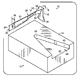
Un outil de fendage de bois spécialisé et un bloc de coupe, utilisés ensemble, permettent la découpe de petit bois à partir de bois à brûler ordinaire d'une manière efficace et sûre. L'outil de fendage utilise une force de levier en plus d'un moment descendant de la tête de découpe pour fendre le bois. Le manche métallique et la tête de découpe métallique sont de préférence constitués d'un même morceau d'acier, selon une configuration perpendiculaire similaire à une herminette. Une lame de cale de fendage située dans le manche exerce des forces de cisaillement transversales afin d'améliorer le fendage, et des surfaces supérieures plates de la tête de découpe et du manche proches du raccord offrent une surface de frappe. Un bloc de coupe complémentaire destiné à caler des rondins de différents diamètres dans une position verticale fixe comporte un évidement en forme de V qui est ouvert sur une extrémité. Le bloc de coupe offre une résistance à l'unique force de levier de l'outil de fendage au cours de l'action de fendage.


Abrégé anglais

A specialized wood splitting tool and chopping block, used together, enable cutting kindling from ordinary firewood in an effective and safe manner. The splitting tool uses leverage in addition to downward momentum of the cutting head to split wood. The metal handle and metal cutting head are preferably formed from a single piece of steel, in a perpendicular configuration similar to an adze. A splitting wedge blade within the handle exerts transverse shear forces to enhance splitting, and flat upper surfaces of the cutting head and the handle near the joint provide a striking surface. A complimentary chopping block for bracing logs of various diameters in a steady upright position has a V-shaped recess that is open on one end. The chopping block provides resistance to the unique leverage of the splitting tool during the splitting action.

Revendications

Note : Les revendications sont présentées dans la langue officielle dans laquelle elles ont été soumises.


Claims
1. A tool for splitting wood, comprising.
a cutting head that includes a first cutting edge and a first substantially
flat surface opposite
the first cutting edge; and
a handle with a longitudinal axis that is substantially perpendicular to the
first cutting edge,
the handle having at least a portion that is joined to the cutting head,
extends away
from the cutting head and defines two side surfaces that converge to form a
second
cutting edge.
2. The tool of claim 1, wherein the portion of the handle that is joined to
the cutting
head has a second substantially flat surface opposite the second cutting edge.
3. The tool of claim 2, wherein the two side surfaces extend from the
second
substantially flat surface to the second cutting edge.
4. The tool of claim 3, wherein the second cutting edge is disposed in-
between the first
cutting edge and the first substantially flat surface.
5. The tool of claim 3, wherein the second substantially flat surface and
the two side
surfaces of the portion of the handle joined to the cutting head have a cross
section that is of
a substantially triangular shape with an apex of the substantially triangular
shape defining
the second cutting edge.
6. The tool of claim 3, wherein the cutting head and the portion of the
handle joined
thereto are made of metal.
7. The tool of claim 6, wherein the cutting head and the portion of the
handle that is
joined to the cutting head are one continuous piece
8. The tool of claim 6, wherein the portion of the handle joined to the
cutting head and
the cutting head are forged together.
6

9. The tool of claim 6, wherein the portion of the handle joined to the
cutting head and
the cutting head are welded together.
10. The tool of claim 6, wherein the portion of the handle joined to the
cutting head and
the cutting head are soldered together.
11. The tool of claim 6, wherein the handle includes a second portion that
extends from
the portion of the handle that is joined to the cutting head.
12. The tool of claim 11, wherein the second portion of the handle includes
a grip.
13. The tool of claim 11, wherein the grip is made of rubber
14. The tool of claim 1, wherein a cross section of the portion of the
handle joined to the
cutting head has a substantially diamond shape with one corner of the
substantially diamond
shape defining the second cutting edge.
15. The tool of claim 1, wherein the cutting head and the portion of the
handle joined
thereto are made of metal.
16. The tool of claim 15, wherein the cutting head and the portion of the
handle that is
joined to the cutting head are one continuous piece.
17. The tool of claim 15, wherein the portion of the handle joined to the
cutting head and
the cutting head are forged together.
18. The tool of claim 15, wherein the portion of the handle joined to the
cutting head and
the cutting head are welded together
19. The tool of claim 15, wherein the portion of the handle joined to the
cutting head and
the cutting head are soldered together.
7

20. The tool of claim 15, wherein the handle includes a second portion that
extends from
the portion of the handle that is joined to the cutting head.
21. The tool of claim 20, wherein the second portion of the handle includes
a grip.
22. The tool of claim 1, wherein the handle includes a second portion that
extends from
the portion of the handle that is joined to the cutting head.
23. The tool of claim 22, wherein the second portion of the handle includes
a grip.
24. The tool of claim 1, wherein the second cutting edge is disposed in-
between the first
cutting edge and the first substantially flat surface.
8

Description

Note : Les descriptions sont présentées dans la langue officielle dans laquelle elles ont été soumises.


CA 02768781 2012-01-20
WO 2011/011518 PCT/US2010/042748
APPARATUS AND METHOD FOR SPLITTING
WOOD INTO KINDLING
Technical Field
Embodiments of the present invention relate to manual tools for splitting or
chopping wood.
Background
Hand tools used to cut wood through the ages often have taken the form of an
axe, an adz, or a splitting wedge used with a blunt sledge hammer. Each type
of tool
has features that are useful for different purposes, but each tool also has
certain
limitations. For example, an axe or hatchet has a metal blade in line with the
handle, a
useful configuration for efficiently exerting a downward force to split
relatively small logs
with a single blow. However, if the single blow is not energetic enough to
split the
wood, the axe may become stuck in the wood. Dislodging an axe stuck in a piece
of
wood is an awkward, unpredictable, and risky activity. Larger logs benefit
from the use
of splitting wedges in which a wedge having a sharp blade is separate from a
blunt
sledge hammer used to safely drive the wedge into the wood with multiple
blows. If the
wedge gets stuck, a second or even a third wedge may be driven into the same
piece
of wood to multiply the splitting force. Drawbacks of such a "sledge and
wedge" system
include the weight of the sledge hammer and suitability for large pieces of
wood as
opposed to kindling. An adz is another conventional cutting tool that uses a
chisel or
gouge-shaped blade for hewing and shaping timber. The adz features an axe
blade
oriented perpendicular to the handle, similar to a garden hoe, instead of in
line with the
handle, like a standard axe. Most existing wood-splitting tools are variations
of these
three well known forms, featuring a variety of different cutting head shapes,
handle
forms, and methods of attaching the blade to the handle.
Summary
A novel splitting tool and a specialized chopping block described herein
cooperate to enable kindling to be cut from ordinary firewood in an efficient
and safe
manner with a minimal application of force. The splitting tool applies
leverage in
DWT 150641130 0090091-001 WOO 1

CA 02768781 2012-01-20
WO 2011/011518 PCT/US2010/042748
addition to downward momentum of the cutting head to split wood. Extra
leverage
becomes possible with the use of a metal handle integrated with a metal
cutting head,
the cutting head and handle being formed or attached in a perpendicular
configuration
similar to an adze. However, the splitting tool differs from a conventional
axe or adz in
a number of respects. In addition to the all-metal construction, a widening
profile of the
handle near the cutting head has a unique triangular shape, thereby increasing
the
amount of leverage that may be applied to the wood. A secondary cutting blade
is
integrated into the end of the handle near the cutting head to split wood away
from the
face of the cutting head, thereby preventing the tool from getting stuck in
the wood. In
addition, the integrated flat top surfaces of the cutting head and the handle
near the
joint allow the user to drive the cutting head completely into the wood as
though the
cutting head were a splitting wedge.
The splitting tool is complemented by a specialized chopping block for holding
wood in a steady, upright position. The chopping block features a V-shaped
recess that
is open on one end, allowing the user to slide a kindling log into the
recessed platform
until it is sufficiently braced, thereby accommodating kindling logs of
various diameters.
The chopping block also provides resistance to the downward force of the
splitting tool
during the splitting action.
It is to be understood that this summary is provided as a means for generally
determining what follows in the drawings and detailed description, and is not
intended
to limit the scope of the invention. The foregoing and other objects, features
and
advantages of the invention will be readily understood upon consideration of
the
following detailed description taken in conjunction with the accompanying
drawings.
Brief Description of the Drawings
Fig. 1 is a perspective view of a splitting tool and chopping block system, in
accordance with a preferred embodiment.
Fig. 2 is a side view of the splitting tool showing the cutting head, handle,
and
joints as well as cut lines corresponding to cross sectional views shown in
Figs. 3 - 5.
Fig. 3 is a cross-sectional view of the steel handle shaft and rubber grip
along a
cut line 3-3, shown in Fig. 2.
Fig 4. is a cross-sectional view of the steel handle shaft along a cut line 4-
4,
shown in Fig. 2.
DWT 150641130 0090091-001 WOO 2

CA 02768781 2012-01-20
WO 2011/011518 PCT/US2010/042748
Fig. 5 is a cross-sectional view of the steel handle shaft near the cutting
head,
along a cut line 5-5, shown in Fig. 2.
Fig. 6 is a front view of the cutting head.
Fig. 7 is a top view of the chopping block shown in Fig. 1 in accordance with
a
preferred embodiment.
Fig. 8 is a front view of the chopping block shown in Fig. 1.
Fig. 9 is a cross-sectional view of the chopping block shown in Fig. 1.
Detailed Description of Embodiments of the Invention
Fig. 1 shows a perspective view of the two components described herein: a
splitting tool 10, and a chopping block 12, shown in approximate proportion to
each
other. The splitting tool 10 comprises a handle shaft 14, and, attached
perpendicularly
to a distal end 16 of the handle shaft 14, a tapered cutting head 18. Both
handle shaft
14 and cutting head 18 are preferably made of steel and are preferably forged
or cast
into one continuous steel piece to maximize strength at a joint 19, though
joint 19
generally may be formed by welding, soldering, or another method of
attachment. At a
proximal end 20 of handle shaft 14, opposite cutting head 18, steel handle
shaft 14 is
preferably partially surrounded by a rubber grip 22, covering about half the
length of
handle shaft 14, the rubber grip 22 providing both user comfort and impact
resistance.
Proximal end 20 of handle shaft 14 has an oblong profile that tapers along its
length
toward a mid-section 28 at which the rubber grip 22 ends.
Beyond mid-section 28, toward distal end 16, the cross section of handle shaft
14 widens near joint 19 to a shape that supports a broad, flat, upper handle
shaft
striking surface 30 and a tapered secondary cutting blade 32 on the underside
of
handle shaft 14 to assist the cutting head 18 in splitting wood. Secondary
cutting blade
32 reduces strain on joint 19 to better withstand the forces generated when
prying wood
apart. The butt, or upper surface, of cutting head 18 is also formed into a
flat plane,
providing a clean cutting head striking surface 34 opposite a primary cutting
blade 36.
In a preferred embodiment, striking surfaces 30 and 34 form a single,
integrated flat
plane. If primary cutting blade 36 should become lodged in the wood (because
of the
presence of knots, for example), removing cutting head 18 is made easier by
the
availability of the striking surfaces 30 and 34. By striking these flat
surfaces with a
mallet or other weighty object, an additional downward force is supplied to
either finish
splitting the wood by prying it apart, or to free cutting head 18 for another
attempt.
DWT 150641130 0090091-001 WOO 3

CA 02768781 2012-01-20
WO 2011/011518 PCT/US2010/042748
Fig. 1 also shows a perspective view of the solid wood rectangular chopping
block 12, having as its principal feature a V-shaped recessed platform 42, cut
from its
top surface 44. According to a preferred embodiment, recessed platform 42 has
straight recessed walls 45 and a rounded point 46 opposite an open end 48. For
example, a kindling log may be slid through open end 48, and wedged into
rounded
point 46 in an upright position for processing.
Fig. 2 shows a side view of splitting tool 10 having three sets of cut lines
to
demonstrate variations in the cross-sectional profile along the length of
handle shaft 14.
According to a preferred embodiment, approximate dimensions of handle shaft 14
include a circumference of about 3 inches, and a total length of about 10
inches, of
which a sharp edge on secondary cutting blade 32 extends about three inches
from
joint 19 toward proximal end 20.
Figs. 3 - 5 show specific cross-sectional profiles along cut lines 3-3, 4-4,
and 5-
5, respectively, shown in Fig. 2. Figs. 3 and 4 show that the oblong profile
at proximal
end 20 is preferably oriented so that its vertical dimension 24 exceeds its
horizontal
dimension 26, and that steel handle shaft 14 has a profile in a rounded
diamond shape
38. Fig. 3 additionally shows that the rubber grip 22 surrounding the proximal
end 20 of
handle shaft 14 causes the overall form of the handle to have an oval shape
40. At
mid-section 28 of the steel handle shaft 14, beyond the end of rubber grip 22,
the profile
simply comprises the core rounded diamond shape 38. The cross-sectional
profile of
steel handle shaft 14 near distal end 16 tapers to a point at the bottom, and
the flat top
gradually widens toward joint 19, forming an elongated triangular shape shown
in Fig.
5.
Fig. 6 is an end view of the four-sided cutting head 18 showing the primary
cutting blade 36, the convex curve of the blade profile having a radius of
curvature of
about 3 inches. According to a preferred embodiment, cutting head striking
surface 34,
opposite primary cutting blade 36 is about 1.75 inches wide and .75 inches
deep,
providing ample surface area for use as a striking surface in conjunction with
surface 30
on handle shaft 14. Cutting head 18 is preferably about 4.75 inches long. The
sides of
cutting head 18 are contoured in a concave curve having about a 5 inch radius
of
curvature. As cutting head 18 is driven into the wood, secondary cutting blade
32 on
the bottom of the handle opens a second split at a right angle to the main
split initiated
by primary cutting blade 36 on cutting head 18. This action exerts transverse
shear
forces on the wood to enhance splitting. The mechanical advantage of the
secondary
DWT 150641130 0090091-001 WOO 4

CA 02768781 2012-01-20
WO 2011/011518 PCT/US2010/042748
cutting blade 32 used as a lever, in cooperation with primary cutting blade
36, splits
apart even hard, dense wood with relatively little effort.
Figs. 7 - 9 pertain to chopping block 12, a specialized embodiment that
complements splitting tool 10, to complete a wood chopping system for
kindling. Fig. 7
provides a top view of the solid wood rectangular chopping block 12,
preferably having
approximate outer dimensions including a length 50 of 1.5 ft, a width 52 of
1.0 ft, and a
thickness 54 of 6 inches. According to a preferred embodiment, V-shaped
recessed
platform 42 is cut from one end of chopping block 12 and positioned
symmetrically with
respect to the width 52 of chopping block 12. V-shaped recessed platform 42
preferably has straight sides 56 measuring about 12 inches, and is cut to a
depth of
about 1.5 inches. Open end 48 preferably has a width 57 of about 8 inches,
leaving 2
inches of the solid chopping block 12 raised above the recessed platform 42 on
either
side. Likewise, the projection 58 of each of sides 56 along the length 50 of
the
chopping block 12 is preferably also about 8 inches. Recessed platform 42
provides a
secure base to hold a subject piece of wood steady for splitting by splitting
tool 10, and
a means of resisting the additional leverage imparted to the wood through the
use of
tapered secondary cutting blade 32.
Although certain embodiments have been illustrated and described herein, it
will
be appreciated by those of ordinary skill in the art that a wide variety of
alternative or
equivalent embodiments or implementations calculated to achieve the same
purposes
may be substituted for the embodiments illustrated and described without
departing
from the scope of the present invention. Those with skill in the art will
readily
appreciate that embodiments in accordance with the present invention may be
implemented in a very wide variety of ways. This application is intended to
cover any
adaptations or variations of the embodiments discussed herein.
The terms and expressions which have been employed in the foregoing
specification are used therein as terms of description and not of limitation,
and there is
no intention, in the use of such terms and expressions, to exclude equivalents
of the
features shown and described or portions thereof, it being recognized that the
scope of
the invention is defined and limited only by the claims that follow.
DWT 150641130 0090091-001 WOO 5

Dessin représentatif
Une figure unique qui représente un dessin illustrant l'invention.
États administratifs

2024-08-01 : Dans le cadre de la transition vers les Brevets de nouvelle génération (BNG), la base de données sur les brevets canadiens (BDBC) contient désormais un Historique d'événement plus détaillé, qui reproduit le Journal des événements de notre nouvelle solution interne.

Veuillez noter que les événements débutant par « Inactive : » se réfèrent à des événements qui ne sont plus utilisés dans notre nouvelle solution interne.

Pour une meilleure compréhension de l'état de la demande ou brevet qui figure sur cette page, la rubrique Mise en garde , et les descriptions de Brevet , Historique d'événement , Taxes périodiques et Historique des paiements devraient être consultées.

Historique d'événement

Description Date
Paiement d'une taxe pour le maintien en état jugé conforme 2024-07-22
Requête visant le maintien en état reçue 2024-07-22
Représentant commun nommé 2019-10-30
Accordé par délivrance 2015-12-29
Inactive : Page couverture publiée 2015-12-28
Préoctroi 2015-10-06
Inactive : Taxe finale reçue 2015-10-06
Un avis d'acceptation est envoyé 2015-04-07
Lettre envoyée 2015-04-07
Un avis d'acceptation est envoyé 2015-04-07
Inactive : Approuvée aux fins d'acceptation (AFA) 2015-01-09
Inactive : Q2 réussi 2015-01-09
Modification reçue - modification volontaire 2014-10-08
Inactive : Dem. de l'examinateur par.30(2) Règles 2014-04-10
Inactive : Rapport - Aucun CQ 2014-04-02
Lettre envoyée 2013-06-28
Requête d'examen reçue 2013-06-13
Toutes les exigences pour l'examen - jugée conforme 2013-06-13
Exigences pour une requête d'examen - jugée conforme 2013-06-13
Inactive : Page couverture publiée 2012-03-23
Inactive : Inventeur supprimé 2012-03-06
Inactive : Notice - Entrée phase nat. - Pas de RE 2012-03-06
Demande reçue - PCT 2012-03-05
Inactive : CIB en 1re position 2012-03-05
Inactive : CIB attribuée 2012-03-05
Exigences pour l'entrée dans la phase nationale - jugée conforme 2012-01-20
Demande publiée (accessible au public) 2011-01-27

Historique d'abandonnement

Il n'y a pas d'historique d'abandonnement

Taxes périodiques

Le dernier paiement a été reçu le 2015-06-11

Avis : Si le paiement en totalité n'a pas été reçu au plus tard à la date indiquée, une taxe supplémentaire peut être imposée, soit une des taxes suivantes :

  • taxe de rétablissement ;
  • taxe pour paiement en souffrance ; ou
  • taxe additionnelle pour le renversement d'une péremption réputée.

Les taxes sur les brevets sont ajustées au 1er janvier de chaque année. Les montants ci-dessus sont les montants actuels s'ils sont reçus au plus tard le 31 décembre de l'année en cours.
Veuillez vous référer à la page web des taxes sur les brevets de l'OPIC pour voir tous les montants actuels des taxes.

Titulaires au dossier

Les titulaires actuels et antérieures au dossier sont affichés en ordre alphabétique.

Titulaires actuels au dossier
DANA S. CLARKE
Titulaires antérieures au dossier
S.O.
Les propriétaires antérieurs qui ne figurent pas dans la liste des « Propriétaires au dossier » apparaîtront dans d'autres documents au dossier.
Documents

Pour visionner les fichiers sélectionnés, entrer le code reCAPTCHA :


Pour visualiser une image, cliquer sur un lien dans la colonne description du document. Pour télécharger l'image (les images), cliquer l'une ou plusieurs cases à cocher dans la première colonne et ensuite cliquer sur le bouton "Télécharger sélection en format PDF (archive Zip)" ou le bouton "Télécharger sélection (en un fichier PDF fusionné)".

Liste des documents de brevet publiés et non publiés sur la BDBC .

Si vous avez des difficultés à accéder au contenu, veuillez communiquer avec le Centre de services à la clientèle au 1-866-997-1936, ou envoyer un courriel au Centre de service à la clientèle de l'OPIC.


Description du
Document 
Date
(aaaa-mm-jj) 
Nombre de pages   Taille de l'image (Ko) 
Description 2012-01-19 5 275
Revendications 2012-01-19 2 72
Abrégé 2012-01-19 1 77
Dessins 2012-01-19 2 95
Dessin représentatif 2012-03-06 1 18
Revendications 2014-10-07 3 77
Dessin représentatif 2015-12-01 1 17
Confirmation de soumission électronique 2024-07-21 1 60
Avis d'entree dans la phase nationale 2012-03-05 1 193
Accusé de réception de la requête d'examen 2013-06-27 1 177
Avis du commissaire - Demande jugée acceptable 2015-04-06 1 161
PCT 2012-01-19 9 326
Taxe finale 2015-10-05 1 53