Note : Les descriptions sont présentées dans la langue officielle dans laquelle elles ont été soumises.
CA 02770009 2012-03-05
- 1 -
"Scooter"
***
The present invention relates to a scooter of the type
comprising:
- a main body defining a resting surface for the feet of a
user;
- a front wheel;
- steering means designed to connect said front wheel to
said main body in such a way that it can turn about a steering
axis substantially transverse to said resting surface; and
- a rear wheel connected to said main body.
The scooters present on the market have both wheels of small
diameter, generally from 10 to 12 cm, coated with polyurethane
and wheels of larger diameter - from 12 cm up - coated with
polyurethane, rubber, or else having tyres with or without
innertubes. In general, scooters with wheels of small diameter
are more stable, whereas those with larger wheels run more
smoothly but are more difficult to manoeuvre.
In this context, the object of the present invention is to
provide a scooter characterized by a completely innovative
configuration, particularly suited for envisaging wheels of
"large" diameter, preferably from 15 cm up.
According to the invention, the aforesaid object is achieved
thanks to a scooter having the characteristics recalled in one or
more of the ensuing claims.
The claims form an integral part of the technical teaching
provided herein in relation to the invention.
The invention will now be described, purely by way of non-
limiting example, with reference to the annexed representations,
in which:
- Figure 1 illustrates a perspective view of an embodiment
of the scooter described herein; and
- Figures 2 to 4 illustrate a detail of the front part of
the scooter, in different positions.
In the ensuing description, various specific details are
CA 02770009 2012-03-05
- 2 -
illustrated aimed at an in-depth understanding of the
embodiments. The embodiments may be provided without one or more
of the specific details, or with other methods, components,
materials, etc. In other cases, structures, materials, or
operations that are known have not been described in detail so
that various aspects of the embodiments will not be obscured.
The references used herein are merely for convenience and
hence do not define the sphere of protection of the embodiments.
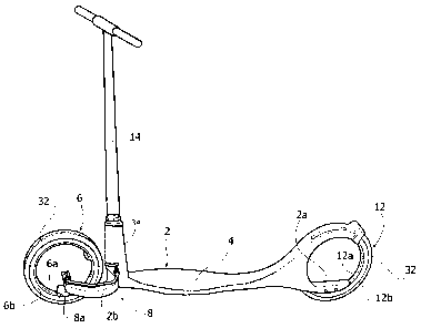
The scooter described herein is designated in the figures by
the reference number 10. In general, it comprises:
- a main body 2 defining a resting surface 4 for the feet of
a user;
- a front wheel 6;
- steering means 8 designed to connect the front wheel to
the main body in such a way that it can turn about a steering
axis I substantially transverse to the resting surface 4; and
- a rear wheel 12 connected to said main body. In
particular, in the scooter described herein the front wheel 6 and
the rear wheel 12 are mounted on the main body so as to be in
line with one another.
According to an important characteristic of the scooter
described herein, one or both of the wheels 6 and 12 are without
hubs. In various embodiments, as in the one illustrated, each
wheel comprises an inner ring (designated by 6a for the front
wheel and by 12a for the rear wheel), or similar structure,
connected to the main body 2 in such a way that it cannot turn
about its own axis, and an outer ring (designated by 6b for the
front wheel and 12b for the rear wheel), or similar structure,
mounted concentric on the inner ring via the interposition of
bearing means (not shown) so as to be rotatable about its own
axis. The outer ring bears the coating - for example, a rubber
coating or a tyre - defining the tread of the wheel, designated
by the reference number 32 for both of the wheels. The bearing
means can be of any type known to the person skilled in the
branch, suited for the purposes indicated, for example rolling
CA 02770009 2012-03-05
- 3 -
bearings of the roller-bearing or ball-bearing type.
In various embodiments, as in the one illustrated, the inner
ring 12a of the rear wheel is rigidly connected to the main body,
whilst the inner ring 6a of the front wheel is connected to the
main body in such a way that it can turn about the first steering
axis I, via the aforesaid steering means.
In preferred embodiments, the main body 2 is connected to
the two wheels 6 and 12 within their respective inner rings 6a,
12a. In various embodiments, as in the one illustrated, the main
body has a connection portion 2a directly fixed to a
corresponding portion of the inner ring 12a, which is located,
preferably, underneath the ideal axis of rotation of the wheel.
In a similar way, in various embodiments the steering means have
a connection portion 8a directly fixed to a corresponding portion
of the inner ring 6a, which is located, preferably, underneath
the ideal axis of rotation of the wheel. The preferred
configuration referred to above causes the points of transmission
of the weight from the body 2 to the wheels 6 and 12 to be
located underneath the ideal axis of rotation of the latter, this
bestowing greater stability upon the means. It should be noted
that the connection portions referred to above can be of any type
in itself already known in said field, and will consequently not
be described herein in detail for reasons of simplicity of
treatment. In various embodiments, the connection between the
parts can for example be obtained via bolts; in this case, the
portions for connection of the inner rings can be thickened and
perforated parts of the ring, provided for receiving fixing
bolts, and the portions for connection of the steering means and
of the main body can present corresponding holes for engagement
by said bolts.
In various embodiments, as in the one illustrated, the inner
ring 6a of the front wheel is connected to the main body in such
a way that it can turn about the aforesaid first steering axis I,
whilst the steering means comprise a rod or handlebar tube 14,
which is mounted so that it can turn on the main body about a
CA 02770009 2012-03-05
- 4 -
second steering axis II, once
again transverse to the plane 4
but distinct from the first axis I. In particular, the second
steering axis is closer to the resting surface 4 than the first
axis. In a way in itself known in the art, the rod or tube 14 is
mounted so that it can turn about the first axis I within a
sleeve portion 34 of the main body 2. It should be noted that the
configuration referred to above enables equipping the scooter
with a front wheel of large diameter, at the same time
maintaining an ergonomic configuration of the body of the scooter
and of the handlebar that enables the user to assume a riding
position that is substantially the same as the one typically
adopted in scooters with wheels of small diameter. In particular,
in various embodiments, as in the one illustrated, the resting
surface 4 is relatively close to the ground, and the rod of the
handlebar, or rather the sleeve portion 34 that receives it, is
set immediately up against the front end of said surface,
preferably the rod of the handlebar assuming an orientation
substantially orthogonal to the resting surface itself. In
various embodiments, as in the one illustrated, the first and
second steering axes are substantially parallel to one another
and preferably contained in the same ideal plane containing also
the wheel 6.
In various particularly preferred embodiments, the distance
between the first and second steering axes in a longitudinal
direction of the main body is such that the front wheel falls
almost tangential to the sleeve portion of said body (not having,
obviously, to come into contact therewith). As may be seen from
Figure 1, the configuration that derives therefrom is extremely
compact.
In various embodiments, such as the one illustrated, the
steering means 8 comprise a mechanism for transmission of the
motion designed to turn the inner ring of the front wheel about
the first axis I as a result of rotation of the handlebar about
the second axis II.
In various preferred embodiments, as in the one illustrated,
CA 02770009 2012-03-05
- 5 -
said transmission mechanism is of the four-bar-linkage type in
which the first and second steering axes correspond to the two
fixed articulation points of the linkage. In various preferred
embodiments, as in the one illustrated, the transmission
mechanism is of the drag-link type, in which rotatably mounted
about the first and second steering axes respectively are two
cranks 18 of equal length in such a way that to a rotation of the
handlebar 14 about the second axis II there corresponds a
rotation by the same amount of the inner ring 6a about the first
axis I.
In the embodiments in which the main body 2 is connected to
the front wheel within the ring 6a, the main body comprises an
arm 2b projecting at the front, which has a substantially C shape
in top plan view, and the distal end of which falls within the
front wheel and carries the first steering axis I. In this case,
the rod of the four-bar linkage (designated by the reference 22),
which connects the two cranks 18, has a profile in top plan view
substantially corresponding to the C shape of the front arm, and
is set in a position corresponding to said arm, above or
underneath it. Figures 3 and 4 illustrate the configuration of
said mechanism in the two end angular positions of the front
wheel. As may be seen from Figures 3 and 4, the C-shaped profile
of both, i.e., the arm 2b and the rod 22, is such as to enable a
given desired steering angle to be reached, also in the direction
of steering concordant with the curvature of said profile from
the base towards its end (clockwise direction as viewed in the
figures), and without causing the wheel to be touched by the rod
22 and/or the arm 2b. In this connection, in various embodiments,
the steering means comprise an appropriate member (not shown)
designed to limit the steering angle of the front wheel so as to
prevent this from coming into contact with the rod 22 or else
with the arm 2b.
Of course, without prejudice to the principle of the
invention, the details of construction and the embodiments may
vary, even significantly, with respect to what has been
CA 02770009 2012-03-05
- 6 -
illustrated herein purely by way of non-limiting example, without
thereby departing from the scope of the invention, as defined by
the annexed claims. In this connection, it should be noted that
the various configurations illustrated above for both of the
wheels 6 and 8 can in actual fact be envisaged also for just one
of said wheels. For example, it is possible to envisage just the
front wheel 6 without a hub, in association with the steering
means 8 referred to above, or else just the rear wheel 12.