Note : Les descriptions sont présentées dans la langue officielle dans laquelle elles ont été soumises.
CA 02770373 2012-02-07
10- 00 36 1
DESCRIPTION
Title of Invention:
FUEL CELL AND METHOD FOR MANUFACTURING SAME
Technical Field
[0001] The present invention relates to a fuel cell and
a method for manufacturing fuel cells.
Background Art
[0002] A fuel cell is a kind of power generating device
generating electric power by oxidizing fuel such as
hydrogen and methanol electrochemically. In recent
years, attention is paid to the fuel cell as a source for
supplying clean energy. Fuel cells are classified by the
type of electrolyte, into phosphoric acid type, molten
carbonate type, solid oxide type and solid polymer
electrolyte type. Among them, the solid polymer
electrolyte fuel cell (also referred to simply as "PEFC") is
a fuel cell arranged to generate power by supplying
hydrogen to one side and oxygen to the other side of a
membrane electrode assembly (also referred to as
"MEA") including electrodes on both sides of an
electrolyte membrane. Since PEFC can provide an
output density comparable to an internal combustion
engine, research is widely performed for practical use as
a power source for an electric vehicle and other
applications.
[0003] In general, PEFC is in the form of fuel cell
stack including a plurality of unit cells each including
integrally a solid polymer electrolyte membrane, and
hydrogen side and oxygen side electrodes confronting
-1-
CA 02770373 2012-02-07
10-00361
each other across the solid polymer electrolyte
membrane. These unit cells are stacked through
separator(s). Between each separator and an adjacent
electrode, there is provided a gas diffusion layer of
porous material normally having an electric conductivity.
The gas diffusion layer is arranged to undertake a role to
enable stable exchange of hydrogen, oxygen, water,
electrons, heat etc., among the electrode layer and an
external circuit.
[0004] As a fuel cell for vehicles, wide use is made of
a stack type fuel cell including a stack of unit cells each
of which includes a sheet-shaped MEA and a sheet-
shaped separator. Normally, the thickness of a unit cell
is smaller than or equal to 10mm. Within this thickness,
the unit cell is required to allow simultaneous flows of
various fluids including a fuel gas and an oxidizing gas,
and further including other fluid (such as a cooling
water) in some cases. Therefore, the unit cell requires a
complicated seal structure provided for each fluid
passage, and this requirement contributes to
deterioration of the productivity of fuel cells.
[0005] As such seal technique, there are known a
technique using a repulsion force of an elastic member,
a technique using adhesion or sticking, a technique
using fixing or pressing with compressive material, and a
technique using mechanical deformation such as staking
or caulking. Among these, the technique using the
repulsion force of the elastic material is widely used
because of advantages, 1) high reliability, 2) high
durability, and 3) possibility of exfoliation or peeling.
However, this technique is limited in the reduction of the
-2-
CA 02770373 2012-02-07
10-00361
thickness and the size of the fuel cell because of the
necessity of a predetermined margin for contraction or
squash.
[0006] The technique using, as sealing material, the
adhesive (liquid material after coating; and
adhesiveness is achieved by hardening or curing) is
advantageous for the reduction of thickness and size
since the margin for contraction or squash is not needed.
However, there is a need for preventing contact of
material other than the material to be bonded, to the
surface coated with the adhesive before hardening.
Moreover, at the time of layer stack of unit cells coated
with the adhesive, the adhesive is flowable until
hardening. Therefore, though minute position
adjustment is possible, the lamination is liable to shift to
a deviated position by external cause or other influence.
[0007] The technique using, as sealing material, the
sticky agent (gel-like solid material after coating; and
adhesiveness is achieved by pressure; also called
pressure sensitive adhesive) is advantageous for the
reduction of thickness and size since the margin for
contraction or squash is not needed. A patent document
1 discloses a technique using the sticky agent.
Prior Art Literature
Patent Document
[0008] Patent Document 1: US 2002/068211A.
Disclosure of Invention
Problem to be solved by the Invention
-3-
CA 02770373 2012-02-07
10-00361
[0009] However, in the technique disclosed in the
patent document 1, the sticking agent does not have a
flowability unlike the adhesive. Therefore, the position
adjustment is unfeasible at the time of layer stack of
unit cells, and there is a need for a precision position
control apparatus not requiring the position adjustment
after the layer stacking.
[0010] The present invention is devised to solve the
above-mentioned problems. It is an object of the
present invention to provide fuel cell and production
method enabling position adjustment at the time of
stacking unit cells.
Means for solving the problem(s)
[0011] After keen research for solving the above-
mentioned problems, the present invention has been
completed by the inventor with finding that the position
adjustment becomes feasible at the time of stacking unit
cells by the use of a self-fusing seal material having a
specified tack property.
Effect of the present invention
[0012] The fuel cell according to the present invention
is provided with a self-fusing seal material having a
certain tack property. This self-fusing seal material
does not develop a tack property under a pressure at a
level of a pressure generated by provisional lamination
of unit cells of the fuel cell. Therefore, the position
adjustment is feasible after the provisional lamination.
After the position adjustment, it is possible to produce a
-4-
CA 02770373 2013-04-23
strong adhesive force by pressurization, so that the
productivity of the fuel cell can be improved.
In one aspect, the invention provides a fuel cell
comprising a lamination of a membrane electrode
assembly including an anode electrode layer and a
cathode electrode layer on opposite sides of an
electrolyte membrane, and a separator, the fuel cell
further comprising a self-fusing seal material provided at
an outer circumference portion of the membrane
electrode assembly or the separator, the fuel cell further
includes a tack preventing layer on a surface of the self-
fusing seal material.
In one aspect, the invention provides a fuel cell
production method, comprising:
(1) coating a self-fusing seal material on an outer
circumference portion of one or more selected from a
group consisting of an anode electrode layer and a cathode
electrode layer, an electrolyte membrane, and a separator;
(2) hardening the self-fusing seal material;
(3) forming a tack preventing layer on a surface of
the self-fusing seal material;
(4) forming a lamination by layering a membrane
electrode assembly formed by sandwiching the electrolyte
membrane between the anode electrode layer and the
cathode electrode layer with the separator;
(5) adhering the lamination by pressurizing the
lamination.
Brief Description of Drawings
[0013]
FIG. 1 is a sectional view schematically showing the
construction of a solid polymer fuel cell.
FIG. 2 is an enlarged sectional view schematically
showing parts of the solid polymer fuel cell shown in FIG.
1, on an enlarged scale.
-5-
CA 02770373 2013-04-23
FIG. 3 is an enlarged partial sectional view
schematically showing a first preferred embodiment of
placement of a self-fusing seal material in a fuel cell
according to the present invention.
FIG. 4 is an enlarged partial sectional view
schematically showing a second preferred embodiment of
the placement of the self-fusing seal material in the fuel
cell according to the present invention.
FIG. 5 is an enlarged partial sectional view
schematically showing a third preferred embodiment of
the placement of the self-fusing seal material in the fuel
cell according to the present invention.
FIG. 6 is an enlarged partial sectional view
schematically showing a fourth preferred embodiment of
the placement of the self-fusing seal material in the fuel
cell according to the present invention.
FIG. 7 is an enlarged partial sectional view
schematically showing a fifth preferred embodiment of
the placement of the self-fusing seal material in the fuel
cell according to the present invention.
-5a-
CA 02770373 2012-02-07
10-00361
Modes for Carrying out the Invention
[0014] The present invention is explained hereinafter
with reference to the drawings. In explanation of the
drawings, the same element is given the same reference
numeral and repetitive explanation is omitted. In the
drawings, the proportions of dimensions may be
exaggerated for the convenience of explanation, and
may be unequal to the actual proportions in some cases.
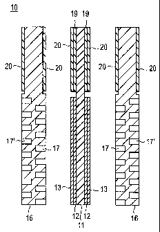
[0015] (Overall Construction of Fuel Cell)
FIG. 1 schematically shows the structure of a solid
polymer type fuel cell 10 of a preferred embodiment. In
fuel cell 10, a membrane electrode assembly 18 includes
a pair of catalyst layers 12 (anode catalyst layer and
cathode catalyst layer) disposed on both sides of a solid
polymer electrolyte membrane 11 in confrontation to
each other. This laminate structure is sandwiched
between a pair of gas diffusion layers 13 (anode side gas
diffusion layer and cathode side gas diffusion layer).
The member electrode assembly 18 is referred to as MEA,
and the assembly of solid polymer electrolyte membrane
11 and catalyst layers 12 is referred to as CCM, in some
cases. In FIG. 1, each of gas diffusion layers 13
includes a base material or substrate 15 and a
microporous layer (MPL) 14, which is put in contact with
the catalyst layer 12. However, the microporous layer
(MPL) 14 is not indispensable, and the gas diffusion
layers 13 may be made up only of the base material 15.
A pair of separators 16 (anode side separator and
cathode side separator) are disposed on the outer sides
of base materials 15. Each separator 16 has a groove
structure for forming gas passage(s) 17 (fuel gas on the
-6-
CA 02770373 2012-02-07
10-00361
anode side, and an oxidizing agent gas on the cathode
side), and water passage(s) 17'. The solid polymer type
fuel cell is constructed in this way.
[0016] FIG. 2 is a sectional view schematically
showing parts of the solid polymer fuel cell 10 of FIG. 1
on an enlarged scale. As shown in FIG. 2, an end
portion of the electrolyte membrane 11 of solid polymer
fuel cell 10 is provided with self-fusing seal material 20.
[0017] As the sealing technique provided for the unit
cell of the fuel cell, there are the technique using the
adhesive and the technique using the sticking agent, as
mentioned before. The adhesive and sticking agent do
not require a margin for contraction or squash, so that
these techniques are advantageous for reduction of
thickness and reduction of size. However, in the
technique using the adhesive, it is necessary to protect
the surface coated with the adhesive so as to prevent
contact with material other than the material to be
bonded, before hardening of the adhesive. Moreover, at
the time of layer stack of unit cells coated with the
adhesive, the adhesive is flowable until hardening.
Therefore, though minute position adjustment is possible,
the unit cells in the stack are liable to shift to a deviated
position by external cause or other influence. In the
technique using the sticking agent (gel-like solid
material after coating; and adhesiveness is achieved by
pressure; also called "pressure sensitive adhesive"), the
sticking agent does not have a flowability unlike the
adhesive. Therefore, the position adjustment is
unfeasible at the time of layer stack of unit cells, and
there is a need for a precision position control apparatus
-7-
CA 02770373 2012-02-07
10-00361
not requiring the position adjustment after the layer
stacking.
[0018] By contrast, the fuel cell according to the
present invention includes self-fusing seal material
having a predetermined tack characteristic. This self-
fusing seal material is a seal material which can join
contact surfaces of seal members of the self-fusing seal
material after hardening with each other by fusion at the
room temperature or higher temperature raised by
heating, by putting or pressing the seal members in
contact with each other. Such a self-fusing seal material
does not develop the tack characteristic at pressures
produced at the time of stack of a considerable number
of unit cells for the fuel cell. Therefore, the structure
using the self-fusing seal material can allow the position
adjustment after provisional lamination of the fuel cell
stack. After the position adjustment, the self-fusing seal
material can develop a strong adhesive force by
pressurization. As a result, this structure can improve
the productivity of fuel cells.
[0019] FIG. 2 shows the example in which the self-
fusing seal material is disposed in the end portion of the
electrolyte membrane. However, the position of the
self-fusing seal material is not limited to the position
shown in FIG. 2. The self-fusing seal material may be
disposed in an end portion of the membrane electrode
assembly or the before-mentioned separators.
Concretely, the self-fusing seal material 20 may be
disposed in end portions of the catalyst layers (the
anode catalyst layer and the cathode catalyst layer), the
gas diffusion layers and the separators. More
-8-
CA 02770373 2012-02-07
10-00361
specifically, the self-fusing seal material may be
desirably disposed in an end portion of at least one
selected from the group including the electrolyte
membrane, the catalyst layers, the gas diffusion layers
and the separators. Among these positions, the end
portion(s) of the gas diffusion layer or layers is
preferable because the porous structure produces a
strong anchor effect, and makes it possible to omit a
special surface treatment before coating of the self-
fusing seal material.
[0020] The following is explanation on preferred
embodiments of the position of self-fusing seal material
20, with reference to FIGS. 3-7. FIGS. 3-7 are partial
enlarged sectional views schematically showing the
preferred embodiments of the placement of the self-
fusing seal material in the fuel cell according to the
present invention.
[0021] In FIG. 3, the self-fusing seal material 20 is
disposed in an end portion of the solid polymer
electrolyte membrane 11. No specific limitation is
imposed on the thickness of self-fusing seal material 20.
For example, in the case of the membrane electrode
assembly including the catalyst layers 12 and gas
diffusion layers 13 as shown in FIG. 3, the thickness of a
layer of the self-fusing seal material 20 may be set
substantially equal to the sum of the thickness of
catalyst layer 12 and the thickness of gas diffusion layer
13. Similarly, in the case of the membrane electrode
assembly including only the catalyst layers 12 (including
no gas diffusion layers 13), the thickness of the layer of
the self-fusing seal material 20 may be set substantially
-9-
CA 02770373 2012-02-07
10-00361
equal to the thickness of catalyst layer 12. In this way,
it is possible to make substantially uniform the total
thickness of the membrane electrode assembly and
hence the total thickness of the lamination of each unit
cell of the fuel cell.
[0022] In the example of FIG. 3, the end portion of
solid polymer electrolyte membrane 11 is provided with
the self-fusing seal material 20 alone. However, it is
optional to interpose a reinforcement or reinforcing layer
19 between the self-fusing seal material 20 and the solid
polymer electrolyte membrane 11 as shown in FIG. 4.
Materials known in the technical field can be used as the
material of reinforcement layer 19 with no specific
limitation. One example of the material of reinforcement
layer 19 is polyethylene terephthalate (PET). No specific
limitation is imposed on the thickness of reinforcement
layer 19. In the case of the membrane electrode
assembly including catalyst layers 12 and gas diffusion
layers 13, the total thickness of the layer of the self-
fusing seal material 20 and the reinforcement layer 19
may be set substantially equal to the sum of the
thickness of catalyst layer 12 and the thickness of gas
diffusion layer 13. Similarly, in the case of the
membrane electrode assembly including only the catalyst
layers 12 (including no gas diffusion layers 13), the total
thickness of the reinforcement layer 19 and the layer of
self-fusing seal material 20 may be set substantially
equal to the thickness of catalyst layer 12. In this way,
it is possible to make substantially uniform the total
thickness of the membrane electrode assembly and
-10-
CA 02770373 2012-02-07
10-00361
hence the total thickness of the lamination of each unit
cell of the fuel cell.
[0023] In the examples of FIG. 3 and FIG. 4, the self-
fusing seal material 20 or the combination of self-fusing
seal material 20 and reinforce layer 19 is formed on the
end portion of solid polymer electrolyte membrane 11 at
a position apart from the end of catalyst layer 12 or gas
diffusion layer 13. However, it is optional to form the
self-fusing seal material 20 or the combination of self-
fusing seal material 20 and reinforce layer 19 on the end
portion of solid polymer electrolyte membrane 11 so that
the self-fusing seal material 20 or the combination of
self-fusing seal material 20 and reinforce layer 19 is in
contact with the end of catalyst layer 12 or gas diffusion
layer 13. The self-fusing seal material 20 or the
combination of self-fusing seal material 20 and reinforce
layer 19 is formed on the end portion of the solid
polymer electrolyte membrane 11 preferably at the
position separated from the end of the catalyst layer 12
or gas diffusion layer 13. More desirably, the self-fusing
seal material 20 or the combination of self-fusing seal
material 20 and reinforce layer 19 is separated from
each of the ends of the catalyst layer 12 and gas
diffusion layer 13 as shown in FIG. 3 and FIG. 4. In this
configuration, the end portions of the catalyst layers and
gas diffusion layers are not covered by the self-fusing
seal material 20. Accordingly, the catalyst layers and
gas diffusion layers can achieve their functions
effectively over the entire area.
[0024] In FIG. 5, the self-fusing seal material 20 is
disposed on the end portion of catalyst layer 12. No
-11-
DAVAIIMMIWIMMMONOVil0114110,./N4 14.= 9.1WitOind*mxnle=
CA 02770373 2012-02-07
10-00361
specific limitation is imposed on the thickness of the
self-fusing seal material 20. For example, in the case of
the membrane electrode assembly including catalyst
layers 12 and gas diffusion layers 13, the thickness of
the layer of the self-fusing seal material 20 is preferably
set substantially equal to the thickness of gas diffusion
layer 13. Similarly, in the case of the membrane
electrode assembly including only the catalyst layers 12
(including no gas diffusion layers 13), the thickness of
the layer of self-fusing seal material 20 is preferably as
thin as possible, or the end portion of catalyst layer 12
on which the self-fusing seal material 20 is formed is
made thinner so that the total thickness of the self-
fusing seal material 20 and the end portion of catalyst
layer 12 is substantially equal to the thickness of the
rest of catalyst layer 12. In this way, it is possible to
make substantially uniform the total thickness of the
membrane electrode assembly and hence the total
thickness of the lamination of each unit cell of the fuel
cell. In the example of FIG. 5, the self-fusing seal
material 20 alone is formed on the end portion of the
catalyst layer 12. However, it is optional to form the
reinforcement layer 19 between the layer of self-fusing
seal material 20 and the catalyst layer 12 in the same
manner as the arrangement shown in FIG. 4.
[0025] In FIG. 6, the self-fusing seal material 20 is
disposed on the end portion of gas diffusion layer 13.
No specific limitation is imposed on the thickness of the
self-fusing seal material 20. For example, the thickness
of the layer of self-fusing seal material 20 is preferably
as thin as possible, or the end portion of gas diffusion
-12-
CA 02770373 2012-02-07
10-00361
layer 13 on which the self-fusing seal material 20 is
formed is made thinner so that the total thickness of the
self-fusing seal material 20 and the end portion of gas
diffusion layer 13 is substantially equal to the thickness
of the rest of gas diffusion layer 13. In this way, it is
possible to make substantially uniform the total
thickness of the membrane electrode assembly and
hence the total thickness of the lamination of each unit
cell of the fuel cell. In this embodiment, as shown in
FIG. 6, the self-fusing seal material 20 may invade or
penetrate at least partly into the gas diffusion layer 13.
However, because the gas diffusion layer 13 has a
porous structure, the self-fusing seal material 20 can
invade or penetrate into the gas diffusion layer 13 over
the entire depth and thereby improve the sealing
performance. In the example of FIG. 6, the self-fusing
seal material 20 alone is formed on the end portion of
the gas diffusion layer 13. However, it is optional to
form the reinforcement layer 19 between the layer of
self-fusing seal material 20 and the gas diffusion layer
13 in the same manner as the configuration shown in
FIG. 4.
[0026] In FIG. 7, the self-fusing seal material 20 is
provided on the end portion of separator 16. No specific
limitation is imposed on the thickness of the self-fusing
seal material 20. Preferably, the layer of self-fusing
seal material 20 has such a thickness as to provide an
appropriate clearance between unit cells (the membrane
electrode assemblies) in stacking the unit cells (the
membrane electrode assemblies). In the case in which
the self-fusing seal material is formed to have a
-13-
CA 02770373 2012-02-07
10-00361
thickness to ensure a specific tack characteristic of the
self-fusing seal material 20, it is preferable to make
thinner the end portion of the separator 16 where the
self-fusing seal material 20 is formed, as shown in FIG.
15 to cause the gas and cooling water to flow efficiently. In
the example of FIG. 7, the self-fusing seal material 20
alone is formed on the end portion of the or each
separator 16. However, it is optional to form the
reinforcement layer 19 between the layer of self-fusing
20 seal material 20 and the separator 16 in the same
manner as the configuration shown in FIG. 4.
[0027] Among the above-mentioned configurations,
the configurations of FIGS. 3-5 and 7 are desirable.
The configurations of FIGS. 3, 4 and 7 are more
[0028] The following is explanation on the self-fusing
seal material used in the present invention.
[0029] (Self-fusing seal material)
30 In the present invention, the "self-fusing seal
material (self-fusing seal layer)" means material or
-14-
CA 02770373 2012-02-07
10-00361
member characterized by adhesion or adhesive joining
by developing fusion in a contact interface between
materials of the same or similar kinds. The self-fusing
seal material is distinguished definitely from the
"adhesive agent or adhesive" characterized by adhesive
joining by coating the agent to either or both of
confronting adherend surfaces, then bringing both in
contact with each other and thereafter hardening or
curing the agent, and from the "sticking agent"
characterized by adhesive joining by coating the agent
to either or both of confronting adherend surfaces, then
hardening or curing the agent and then bringing both
surfaces in contact with each other.
[0030] In this invention, the "self-fusing seal material
(self-fusing seal layer)" means material or member
which is, in addition to the above-mentioned feature,
characterized by developing a strong self-fusing property
by pressurization while the strong self-fusing property is
not developed under low pressure in the contact
interface of the adherends. More specifically, a self-
fusing force obtained by pressurization at 25 C, 5kPa for
10 minutes (hereinafter also referred to as the self-
fusing force before pressurization) is smaller than
0.01N/mm. The self-fusing force obtained by
pressurization at 25 C, 100kPa for 10 minutes
(hereinafter also referred to as the self-fusing force
after pressurization) is greater than or equal to
0.05N/mm. The self-fusing force is measure by a T peel
test at a peel speed of 50 cm/min. This range is
preferable because the position adjusting is possible
after provisional lamination of unit cells of a fuel cell,
-15-
CA 02770373 2012-02-07
10-00361
and the strong adhesive force can be obtained by
pressurization after the position adjustment, so that the
productivity of the fuel cells can be improved.
[0031] The self-fusing force after pressurization can
be determined by performing the T peel test at the peel
speed of 50cm/min after pressurization at 25 C, 100kPa
for 10 minutes. Preferably, the self-fusing force after
pressurization is greater than or equal to 0.1N/mm. The
following ranges are preferable in the order of
0.15N/mm or higher, 0.2N/mm or higher, 0.3N/mm or
higher, 0.4N/mm or higher, 0.5 N/mm or higher,
1.0N/mm or higher. It is preferable to increase the self-
fusing force after pressurization, so that the upper limit
is not limited specifically. Preferably, the upper limit of
the self-fusing force after pressurization is 1000N/mm.
[0032] Examples of the self-fusing seal material are:
butyl rubber, polyvinyl chloride, ethylene-propylene
rubber, or silicone rubber composition including
polyorgano-siloxane and boron compound. Specifically,
from the viewpoint of the heat resistance and chemical
stability, the silicone rubber composition including
polyorgano-siloxane and boron compound is preferable.
[0033] No specific limitation is imposed on the silicone
rubber composition. It is possible to use known silicone
rubber composition such as the composition disclosed in
JP H10-120904 A. The following composition is
preferable.
[0034] (A) 100 parts by mass of polyorgano-siloxane
represented by a general formula: RaSi0(4-a)/2 (R
represents monovalent hydrocarbon group mutually
-16-
CA 02770373 2012-02-07
10-00361
identical or different, substituted or unsubstituted, a is
1.90-2.70)
(B) 0.1-30 parts by mass of at least one boron
compound selected from boric acids, boric acid
derivatives, polyorganoborosiloxanes.
(C) 0.1-10 parts by mass of organic peroxide.
[0035] Polyorgano-siloxane (A) is a base polymer of
the self-fusing seal material. Polyorgano-siloxane is
represented by an average composition formula:
RaSi0(4-a)/2 (R and a are defined as mentioned above).
Examples of R are: alkyl group such as methyl group,
ethyl group, n-propyl group, isopropyl group, n-butyl
group, n-pentyl group, n-hexyl, n-octyl, and n-decyl;
cycloalkyl group such as cyclopentyl group and
cyclohexyl group; alkenyl group such as vinyl group and
allyl group; aryl group such as phenyl group and
naphthyl group; and substituted hydrocarbon group such
as chloromethyl group and 1, 1, 1-trifluoropropyl group.
In order to obtain good heat resistance, cold resistance
and workability as the silicone rubber, excluding the
later-mentioned alkenyl group, the concentration of
methyl group is preferably 50 mol% or more of the
whole of R, and more preferably 85 mol% or more.
Specifically, when the resistance to radiation, the
resistance to heat and the resistance to cold are
required or important, preferably a desired quantity of
phenyl group is introduced to the molecule. Especially
when the oil resistance and chemical resistance is
required or important, preferably a desired quantity of
1,1,1-trifluoro propyl group is introduced to the
molecule.
-17-
MCOINICIIMIERNINNOMmons¶*..4i-
CA 02770373 2012-02-07
10-00361
[0036] Radicals generated from the organic peroxide
of the later-mentioned component (C) can act to the
methyl group in the component (A) and form a cross-
linking structure, depending on the type of the
component (C). However, in order to obtain the silicone
rubber having good heat resistance and mechanical
properties by causing a wide range of kinds of
component (C) to function in a small amount, it is
preferable to use R containing a certain amount of the
alkenyl group, especially the vinyl group. Preferably,
the contained amount of the vinyl group is less than or
equal to 1 nnol% in view of the heat resistance of
polyorganosiloxane. A more desirable range is 0.02-0.2
mol%. A configuration in which a polymer end is closed
by a group including a silanol group, such as
dimethylhydroxysilyl is preferable since a good self-fusing
property can be obtained.
[0037] a is in the range of 1.90-2.70. A more desirable
range is 1.99-2.01.
[0038] The boron compound of the component (B) is a
constituent providing the self-fusing property after
hardening, to the silicone rubber composition. Examples
of component (B) are: boric acids such as anhydride
boric acid, pyroboric acid, and orthoboric acid;
derivative of boric acid or anhydride boric acid, such as
trimethyl borate, triethyl borate, trimethoxy borate,
triethoxy borate, and trimethoxyboroxin; and
polyorganoborosiloxane, such as polymethylborosiloxane,
including boroxane coupling introduced into polysiloxane
chain. Polyorganoborosiloxane can be obtained by
condensation, by heating, of organoalkoxysilane such as
-18-
akamommmamomoniL4 ViatlffalWainaideltitelOWNMAN Vs>
CA 02770373 2012-02-07
10-00361
dimethyldimethoxysilane and dimethyldiethoxysilane,
and anhydrous boric acid. It is possible to employ one
kind of these or to combine two or more kinds. In view
of the compatibility with polyorganosiloxane of the
component (A), polyorganoborosiloxane is preferable.
[0039] The blending quantity of component (B) is
preferably 0.1-30 parts by mass with respect to 100
parts by mass of component (A). More desirably, the
blending quantity of component (B) is 1-15 mass parts.
In the range smaller than 0.1 parts by mass, the self-
fusing property might not developed after hardening. In
the range greater than 30 parts by mass, the silicone
rubber obtained by hardening might be insufficient in
heat resistance, and lower in mechanical properties.
15 [0040] The organic peroxide of component (C) is a
hardening or curing agent causing a cross-linking
reaction of component (A) by producing radicals by
heating, and thereby hardens or cures the self-fusing
silicone rubber composition. Examples of the organic
peroxide are: acyl type peroxide such as benzoyl
peroxide, bis (p-chlorobenzoyl) peroxide and bis (2,4-
dichlorobenzoil) peroxide; alkyl type peroxide such as
di-tert-buthyl peroxide, 2, 5-dimethy1-2, 5- di (tert-
buthyl peroxy) hexane, tert-buthylcumyl peroxide,
dicumyl peroxide; and ester type organic peroxide such
as tert-buthylperoxybenzoate.
[0041] The usage quantity of component (C) is
preferably 0.1,u10 parts by mass with respect to 100
parts by mass of component (A). A more desirable
range is 0.3,-5 parts by mass. For safe and easy
-19-
_r Si MIMI lam NEWEI izummoasmmrimemumw==.....
CA 02770373 2012-02-07
10-00361
treatment, the component (C) may be in the form of
paste formed by mixing with silicone oil or blend formed
by adsorption to inorganic fine powder.
[0042] Besides the above-mentioned boron compound,
a tin compound (D) may be included. The tin compound
is a component to improve the self-fusing property and
to prevent a so-called "catch cold phenomenon" which is
a phenomenon in which the self-fusing property becomes
lower by a long time process under moisture or damp or
high temperature. Examples of the tin compound are:
tin oxide such as stannic oxide; organic tin salt such as
stannous butyrate, stannous octoate, stannous
decanoate, stannous naphthenate, stannous octenoate,
and stannous oleate; and organic tin compound including
hydrocarbon group coupled directly with tin atom, a such
as dibutyltin diacetate, dibutyltin dioctoate, dibutyltin
di-2-ethylhexoate, dibutyltin dilaurate, dibutyltin
dinnethylate and dimethyltin dioxide. In view of the
compatibility with polyorganosiloxane of component (A),
a preferable example is tin compound useful as
condensation catalyst of a room temperature
vulcanizable silicone rubber.
[0043] The usage quantity of the tin compound in the
case of use of the tin compound is preferably 0.01-10
parts by mass with respect to 100 parts by mass of
component (A). A more desirable range is 0.1-5 parts
by mass. In the range smaller than 0.01 parts by mass,
the effect of restraining the "catch cold phenomenon"
may be eliminated in some cases. In the range
exceeding 10 parts by mass, the tin compound might
impede the curing of the silicone rubber. Moreover, the
-20-
CA 02770373 2012-02-07
cured silicone rubber might be insufficient in heat
resistance and might be lower in mechanical properties.
[0044] According to the need, it is optional to blend
inorganic filler to the self-fusing silicone rubber
composition. The inorganic filler is intended to provide
required stiffness and mechanical properties to the
silicone rubber composition. Examples are: reinforcing
filler such as fumed silica, silica aerogel and precipitated
silica; and non-reinforcing filler such as quartz powder,
fused silica, diatomous earth, calcium carbonate,
titanium oxide, ferric oxide, ferrite and carbon. It is
possible to use one of these singularly, or two or more
of these in combination.
[0045] The inorganic filler can be blended
appropriately in consideration of physical properties of
the rubber obtained after curing, and various properties
to be imparted to the rubber. Generally, it is preferable
to blend the inorganic filler to an upper limit of 1,000
parts by mass with respect to 100 parts by mass of
component (A). In consideration of the workability, a
more desired range of blending is 1-500 parts by mass.
[0046] It is optional to mix, into the silicone rubber
composition, various ingredients known as compounding
ingredients to the silicone rubber, such as pigment, heat
resistance improving agent, antioxidizing agent or
antioxidant, processing aid and organic solvent.
Furthermore, in order to prevent pseudo cross linking, it
is optional to mix alcohol such as methanol, ethanol,
isopropyl alcohol, propylene glycol, and glycerin.
[0047] The silicone rubber composition can be
prepared by cold kneading or hot kneading with a
-21-
CA 02770373 2012-02-07
10-00361
kneading machine such as banbury mixer, kneader, or
roll. The components (A)¨(D) and the optional inorganic
filler can be blended in an arbitrary order of blending or
compounding. In the case of hot kneading with heating,
it is preferable to add the component (B), (C) and (D)
after the mixture is cooled after the hot kneading.
[0048] As the silicone rubber composition, it is
optional to use a commercial product. Examples of the
commercial product are: SE6770 U silicone rubber
compound produced by Toray Dow Corning silicone Co.
Ltd. It is possible to use any of silicone rubber
compositions known in the art.
[0049] The self-fusing force or self-fusing adhesive
force before pressurization of the self-fusing seal
material used in the present invention is preferably
smaller than 0.01N/mm. A more desirable range is
smaller than 0.001N/mm. More desirably, the self-
fusing seal material has no self-fusing force (0 N/mm,
that is) before pressurization. The self-fusing force
before pressurization can be measured by T-shaped
peeling test at a peeling speed of 50cm/min after
pressurization at 5kPa at 25 C for 10 minutes. A
pressure of 5kPa is applied on the assumption of
pressure applied by its own weight when a considerable
number of unit cells of the fuel cell are provisionally
stacked. Preferably, the self-fusing seal material
according to the present invention does not show a self-
fusing property when the self-fusing seal material is
pressed against a confronting self-fusing seal material at
least with a pressure corresponding to its own weight.
-22-
MeatelligliniteMarMitta
CA 02770373 2012-02-07
10-00361
[0050] Preferably, a ball tack at 23 C, of the self-
fusing seal material used in the present invention is
lower than or equal to 3. The ball tack is a ball tack
value measured by J. Dow method specified by JIS
Z0237: 2009. The ball tack becomes greater as the tack
property or tackiness becomes stronger. The ball tack is
preferably smaller than or equal to 2. More desirably,
the ball tack is smaller than or equal to 1. Null ball tack
(ball tack is equal to zero) is especially desirable.
[0051] It is known that a typical self-fusing material
develops a strong fusing adhesive force merely by
contact at room temperature with no pressure (less than
1kPa). However, it is possible to design so as to develop
a desirable physical property of the self-fusing seal
material by employing technique (as disclosed in JP
2566304 B2) forming, in a surface layer, a tack
preventing layer to prevent contact between self-fusing
materials under low pressure. Moreover, technique of
dispersing microcapsules enclosing plasticizer in a base
material layer lower in the self-fusing property (as
disclosed in JP H06-172725 A) is effective for developing
a desired physical property of the self-fusing seal
material. Furthermore, it is possible to adjust the self-
fusing force and tackiness before pressurization and the
self-fusing force after pressurization within a desirable
range by attaching an additive agent to the surface of
self-fusing seal material. No limitation is imposed on
the additive agent as long as the additive agent can
adjust the self-fusing force and tackiness before
pressurization and the self-fusing force after
pressurization within the desirable range. It is
-23-
smeworneendmenorm,A,
CA 02770373 2012-02-07
10- 00 36 1
preferable to use, as the additive agent, fine power and
fine fibers of alumina and silica. Use of alumina powder
and silica powder is more desirable. By using such the
additive agent of such a type adhering to the self-fusing
seal material surface, it is possible to adjust the self-
fusing force and tackiness before pressurization and the
self-fusing force after pressurization within the desirable
range. The blending quantity (coating quantity) of the
additive agent is not limited as long as the above-
mentioned effect is achieved. The blending quantity is
determined appropriately in dependence on the kind of
the additive agent. Though no limitation is imposed on
the average particle or grain size of powder when the
additive agent is in the form of fine powder, the average
particle size is preferably greater than or equal to
0.001pm. A more desirable range is equal to or greater
than 0.01pm. A range equal to or greater than 0.02pm
is still more desirable. In the case of use of fine powder
as the additive agent, the upper limit of the average
particle diameter is preferably equal to smaller than the
thickness of the self-fusing seal material. A range equal
to or smaller than 10 pm is more desirable. A range
equal to or smaller than 5 pm is still more desirable. A
range equal to or smaller than 1 pm is especially
desirable. Thus, in the case of the additive agent in the
form of fine powder, a desirable range of the average
grain diameter is 0.001-10 pm. A more desirable range
is 0.01-5pm. A still more desirable range is 0.02pm-lpm.
It is possible to assume that the additive agent functions
to impede the self-fusion by intervening between the self-
fusing seal materials at low pressures, and to enable
-24-
las = 1 ma ungailat
iMMINOVIROMMUSelmearmanommanaga....r.......
CA 02770373 2012-02-07
10-00361
development of the self fusion by being retracted in the
self-fusing seal material at high pressures. It is possible
to attach the additive agent to at least one surface of the
confronting self-fusing materials.
[0052] In the present invention, as to members forming
MEA and PEFC other than the self-fusing seal material, it is
possible use construction known in the field of the fuel
cell without modification or with appropriate modification.
The following is explanation on elements constituting MEA
and PEFC. However, the invention is not limited to the
following modes.
[0053] (Solid polymer electrolyte membrane)
The solid polymer electrolyte membrane is composed of
polymer electrolyte having proton conductivity, and has a
function to cause protons generated in the anode catalyst
layer at the time of operation of the solid polymer fuel cell,
to permeate selectively to the cathode catalyst layer in the
direction of the membrane thickness. Moreover, the solid
polymer electrolyte membrane has a function as a partition
to prevent mixing of the fuel gas supplied to the anode
side and the oxidizing gas supplied to the cathode side.
[0054] No specific limitation is imposed on the structure
of the solid polymer electrolyte membrane. It is possible
to employ membranes of polymer electrolytes known in
the technical field of the fuel cells. Solid polymer
electrolyte membranes are classified into fluorine solid
polymer electrolyte membranes and hydrocarbon solid
polymer electrolyte membranes according to the kinds of
constituent polymer electrolytes.
[0055] Examples of polymer electrolytes constituting the
fluorine solid polymer electrolyte membrane are:
-25-
akansgema..... 4.4 4MIROVAIMMemseperdwmamansor
CA 02770373 2012-02-07
10-00361
perfluorocarbonsulfonic acid type polymer such as nafion
(registered trademark, product of Dupont), aciplex
(registered trademark, product of Asahi Kasei
corporation) and flemion (registered trademark, product
of Asahl Glass Co. Ltd.), perfluorocarbon phosphorous
acid type polymer, trifluorostyrenesulfonic acid type
polymer, ethylenetetrafluoroethylene-g-styrenesulfonic
acid polymer, ethylene-tetrafluoroethylene copolymer
and polyvinylidene fluoride-perfluorocarbon sulfonic acid
type polymer. In view of the power generating
properties such as heat resistance and chemical stability,
use of these fluorine polymer electrolyte membranes is
desirable. Use of fluorine polymer electrolyte membrane
made up from perfluorocarbonsulfonic acid type polymer
is more desirable.
[0056] Examples of polymer electrolyte constituting
hydrocarbon based solid polymer electrolyte membrane
are: sulfonated polyethersulfone (S-PES), sulfonated
polyaryl ether ketone, sulfonated polybenzimidazolealkyl,
phosphonated polybenzimidazolealkyl, sulfonated
polystyrene, sulfonated polyetheretherketone (S-PEEK)
and sulfonated polyphenylene (S-PPP). Use of these
hydrocarbon based polymer electrolyte membranes is
desirable from production viewpoints such as
inexpensive raw materials, easy and convenient
production process, and wide selections of materials. It
is possible to use only one or two or more in
combination, of the above-mentioned ion exchange
resins.
[0057] It is optional to use, as the polymer electrolyte,
material other than the polymer electrolytes constituting
-26-
MOMUMa guakhannikitarawasratossea,
CA 02770373 2012-02-07
10-00361
the above-mentioned solid polymer electrolyte
membranes. For example, liquid, solid and gel materials
having high proton conductivity are usable. Examples
are: solid acids of phosphoric acid, sulfuric acid,
antimonic acid, stannic acid and heteropoly acid;
hydrocarbon polymer doped with inorganic acid such as
phosphoric acid; organic/inorganic hybrid polymer partly
replaced by proton conductive functional group; and gel-
like proton conductive material including polymer matrix
impregnated with phosphoric acid solution or sulfuric
acid solution. It is possible to use, as the polymer
electrolyte, mixed conductor having proton conductivity
and electron conductivity.
[0058] The thickness of the solid polymer electrolyte
membrane can be determined appropriately in
consideration of characteristics of the membrane
electrode assembly and polymer electrode, without no
specific limitation. However, a desirable range of the
thickness of the solid polymer electrode electrolyte
membrane is 5-300pm. A more desirable range is
5-200pm. A still more desirable range is 10-150pm. A
specifically desirable range is 15-50pm. With the
thickness within these ranges, it is possible to control
the balance among the strength at the time of forming
the membrane, the durability during use, and the output
characteristic during use.
[0059] (Catalyst Layers)
There are the anode catalyst layer and the cathode
catalyst layer. Hereinafter, "catalyst layer" is simply
used when no distinction is made between the anode
catalyst layer and cathode catalyst layer. The catalyst
-27-
_
CA 02770373 2012-02-07
10-00361
layers have a function to produce electric energy
through electrochemical reaction. The anode catalyst
layer generates protons and electrons by the oxidation
reaction of hydrogen. Protons and electrons generated
in the anode catalyst layer are used for the reduction
reaction of oxygen in the cathode catalyst layer.
[0060] The catalyst layers include an electrode
catalyst having a conductive carrier supporting catalyst
component, and a polymer electrolyte. It is possible to
employ any of catalyst layer configurations known in the
technical field of the fuel cell, with no specific limitation.
[0061] (Conductive Carrier)
The conductive carrier is a carrier supporting the
catalyst component, and having electric conductivity.
The conductive carrier is required to have a specific
surface area sufficient to carry the catalyst component
in a desirable dispersed state, and to have a sufficient
electron conductivity. As to the composition of the
conductive carrier, a preferable main component is
carbon. Examples of the material of conductive carrier
are: carbon black, activated carbon, coke, natural
graphite and artificial graphite. The expression, "main
component is carbon" means that the material includes
carbon as a main component, and includes both of the
meaning that only carbon atoms are included, and the
meaning that it is made up substantially of carbon atoms.
In some cases, in order to improve a characteristic of
the fuel cell, an element or elements other than carbon
atoms may be included. The expression "it is made up
substantially of carbon atoms" means that inclusion of
-28-
.11111NRIMMIN9VIMMED.E.S81414H411=16/16=FX,
4APIONWIMMINMaxvomaraVAIMIMmer=ORM.X.roa
CA 02770373 2012-02-07
10-00361
impurities in an amount smaller than or equal to about
2-3 mass% is allowable.
[0062] No special limitation is imposed on the BET
(Brunauer-Emmet-Teller) specific surface area of the
conductive carrier as long as the catalyst component can
be supported in a highly dispersed state. However, a
desirable range isl 00-1500 m2/g. A more desirable range
is 600-1000 m2/g. Within these ranges, it is possible to
adequately control the balance between the dispersion of
the catalyst component on the conductive carrier and the
rate of effective utilization of the catalyst component.
[0063] Though no special limitation is imposed on the
average particle diameter of the conductive carrier,
normally the average particle diameter is in a range of
5-200nm. A preferable range is about 10-100nm. As the
average particle diameter of the conductive carrier, values
obtained by a primary particle diameter measuring method
by a transmission electron microscope (TEM) are employed.
[0064] (Catalyst Component)
The catalyst component has a function to perform
catalytic action in the electrochemical reaction. The
catalyst component carried on the conductive carrier is not
limited as long as the above-mentioned catalytic action
can be performed to promote the electrochemical reaction.
It is possible to employ known catalysts appropriately.
Examples of the catalyst components are: metals such as
platinum, ruthenium, iridium, rhodium, palladium, osmium,
tungsten, lead, iron, chrome, cobalt, nickel, manganese,
vanadium, molybdenum, gallium, and aluminum, and
alloys of these metals. Preferably, the catalyst
component includes at least platinum in view of good
-29-
+14.=611WIWIROMINIMPC.,
CA 02770373 2012-02-07
10-00361
catalytic activity and resistance to elution. In the case
of alloy employed as the catalyst component, the
composition of the alloy can be selected appropriately by
a person skilled in the art in dependence on the kinds of
metals in the alloy. Preferably, the platinum content is
about 30-90 at% and the content of other metal or
metals in the allow is about 10,-70 at%. In general, an
alloy is material having metallic properties, obtained by
adding, to one metal element, one or more metallic
elements or non-metal. The structure of the alloy may
be eutectic alloy which is a mixture of constituent
elements in different crystals, a solid solution in which
constituent elements are blend in completely, and a
compound formed by constituent elements such as
intermetallic compound and a compound of metal and
non-metal. Any of these structures can be employed. It
is possible to determine the alloy structure by using ICP
optical emission spectrometry.
[0065] No special limitation is imposed on the shape
and size of the catalyst component. It is possible to
employ the shape and size of known catalyst
components. A preferable shape of the catalyst
component is granular. The average particle diameter of
catalyst component particles is desirably in a range of
0.5-30 nm, and more desirably in a range of 1-20nm.
Within these ranges, it is possible to properly control the
balance between the catalyst utilization rate relating to
the area of effective electrode surface on which the
electrochemical reaction proceeds, and the ease of the
support of the carrier. The average particle diameter of
the catalyst component particles can be calculated as an
-30-
baidtill.01101tlin 1..8.6.1.1.annar=veheasownsavamenx.r..
CA 02770373 2012-02-07
10-00361
average value of a crystallite diameter determined from
a full width at half maximum of diffraction peak of the
catalyst component particles in X-ray diffraction analysis
and a particle diameter of the catalyst component
obtained from images of the transmission electron
microscope.
[0066] No limitation is imposed on the ratio of the
conductive carrier content and the catalyst component
content in the electrode catalyst. The content
percentage of the catalyst component (supported
quantity) is preferably in a range of 5-70 mass% with
respect to the total mass of the electrode catalyst. A
more desirable range is 10-60 mass%, and a still more
desirable range is 30-55 mass%. When the content rate
of the catalyst component is equal to or greater than 5
mass%, the catalyst component can perform the catalyst
function of the electrode catalyst sufficiently, and hence
contributes to improvement in the power generating
performance of the solid polymer fuel cell. When the
content rate of the catalyst component is equal to or
smaller than 70 mass%, agglomeration of catalyst
component on the surface of the conductive carrier is
restrained, and the catalyst component is supported in a
desirable higher dispersed state. The above-mentioned
ratio of the contents is determined by using values
measured by the ICP optical emission spectrometry.
[0067] (Polymer Electrolyte)
The polymer electrode has a function of improving the
proton conductivity of the catalyst layer. As to the
configuration of the polymer electrolyte included in the
-31-
1111.1111MEINEMMEMBra awastlanummestiventissunsmamisk
CA 02770373 2012-02-07
10-00361
catalyst layer, knowledge known in the technical field of
the fuel cell can be used appropriately without limitation.
For example, as the polymer electrolyte included in the
catalyst layer, it is possible to use the polymer
electrolyte forming the above-mentioned solid polymer
electrolyte membrane. Accordingly, repetition of
detailed explanation about the polymer electrolyte is
omitted here. The polymer electrolyte included in the
catalyst layer may include only one kind or may include
two or more kinds.
[0068] The ion exchange capacity of the polymer
electrolyte included in the catalyst layer is preferably in
a range of 0.8-1.5mmol/g from the viewpoint of good
ion conductivity. A more desirable range is
1.0,-1.5mmol/g. The ion exchange capacity of the
polymer electrolyte means a number of moles of sulfonic
acid group per unit dry mass in the polymer electrolyte.
It is possible to determine a value of the ion exchange
capacity by preparing a solid polymer electrolyte by
removing a dispersion medium from a polymer
electrolyte dispersion liquid by drying by heat, and
performing neutralizing titration of the solid polymer
electrolyte.
[0069] No limitation is imposed on the polymer
electrolyte content in the catalyst layer. However, the
mass ratio of the quantity of the polymer electrolyte to
the quantity of the conductive carrier in the catalyst
layer (the mass ratio equaling the polymer electrolyte
content/the conductive carrier content) is preferably in a
range of 0.5,µ,2Ø A more desirable range is 0.6-1.5. A
-32-
CA 02770373 2012-02-07
10-00361
still more desirable range is 0.8-1.3. The condition that
the mass ratio of the polymer electrolyte/conductive
carrier is equal to or greater than 0.8 is desirable from
the viewpoint of restraint of the internal resistance of
the membrane electrode assembly. The condition that
the mass ratio of the polymer electrolyte/conductive
carrier is equal to or smaller than 1.3 is desirable from
the viewpoint of restraint of flooding.
[0070] It is optional to add water repellent and
various other additives in the form of coating or
inclusion, to each catalyst layer, specifically to the
conductive carrier surface and the polymer electrolyte.
With the addition of water repellent, it is possible to
enhance the water repellant property of the catalyst
layer, and to discharge water produced at the time of
power generation promptly. The mixed quantity of the
water repellent can be determined appropriately within a
range exerting no influence on the operations and
effects of the present invention. As the water repellent,
it is possible to use the above-mentioned example
desirably.
[0071] Though there is no specific limitation, the
thickness of the catalyst layer according to the present
invention is preferably in a range 0.1-100pm. A more
desirable range is 1-201Jm. The condition that the
thickness of the catalyst layer is equal to or greater than
0.1pm is desirable in the point of obtaining a desired
quantity of power. The condition that the thickness of
the catalyst layer is equal to or smaller than 100pm is
desirable in the point of maintaining high output.
[0072] The membrane electrode assembly can be
produced by forming the anode side catalyst layer and
-33-
-415101IMIRMEMEIMISSIMBOIWENIM4A.2
CA 02770373 2012-02-07
10-00 36 1
cathode side catalyst layer on both sides of the solid
polymer electrolyte membrane by a known method, and
sandwiching the thud-obtained lamination between gas
diffusion layers formed by the above-mentioned method.
[0073] The catalyst layers can be produced by coating
catalyst ink made up of the electrode catalyst, polymer
electrolyte and solvent, on the solid polymer electrolyte
membrane by a known method such as spraying,
transfer method, doctor blade method and die coater
method.
[0074] The quantity of catalyst ink coating and the
solid polymer electrolyte membrane is not limited as
long as the electrode catalyst can perform the operation
of catalyzing the electrochemical reaction sufficiently.
Preferably, the coating is performed so that the mass of
the catalyst component per unit area is in a range of
0.05-1 mg/cm2. The thickness of the coated catalyst
ink after drying is preferably in a range of 5-30pm. The
coating quantity and coating thickness need not be the
same between the anode side and the cathode side. It
is possible to adjust the coating quantity and thickness
individually for the anode side and the cathode side.
[0075] (Gas diffusion layers)
A pair of the gas diffusion layers are so disposed that
MEA composed of the above-mentioned electrolyte
membrane and cathode layers is sandwiched between
the gas diffusion layers. The gas diffusion layers
function to promote the diffusion, to the catalyst layers,
of the gas (the fuel gas on the anode side; the oxidizing
gas on the cathode side) supplied through the later-
mentioned gas passage of the separators, and serve as
the electron conduction path.
-34-
AVIX10/14MIMIRMIWIMOVISOMIYMIIMSKY. Am wow mvsnlemwram.x..........
CA 02770373 2012-02-07
10-00361
[0076] The material forming the base material of the
gas diffusion layers is not limited, and knowledge known
in the art can be used. Examples are: sheet materials
having conductivity and porosity, such as fabric of
carbon product, paper-shaped product of paper making,
felt, and nonwoven fabric. The thickness of the base
material can be determined appropriately in
consideration of characteristics of the resulting gas
diffusion layer. A desirable range is 30-500pm. With
the base material having the thickness in this range, it is
possible to control the balance between the mechanical
strength and the diffusivity of gas and water.
[0077] Preferably, a hydrophilic treatment is
performed to the gas diffusion layers. The gas diffusion
layers processed by the hydrophilic treatment can
promote discharge of excess amount of water existing
(or flowing) in the catalyst layers, and prevent flooding
phenomenon effectively. Examples of the hydrophilic
treatment applied to the gas diffusion layers are:
coating of titanium oxide to the carbon base material
surface and treatment of modifying the carbon base
material surface with acid functionality. These examples
are not limiting. It is possible to employ other
hydrophilic treatments.
[0078] Moreover, in order to promote discharge of
excessive water existing in or on the catalyst layers and
to prevent occurrence of the flooding phenomenon, the
gas diffusion layers may have a microporous layer
(carbon particle layer) containing carbon particles, on
the catalyst layer's side of the base material.
[0079] As the carbon particles included in the
microporous layer (carbon particle layer), it is possible
-35-
WAIMINIIMR11601.141.1MIMMIMPOWINA.f.
41m. **.morr.,...
CA 02770373 2012-02-07
10-00361
to employ known material such as carbon black, graphite,
and expanded graphite without special limitation.
Specifically, carbon black such as oil furnace black,
channel black, lamp black, thermal black and acetylene
black is preferable because of superior electron
conductivity and great specific surface area. Preferably,
the average particle diameter of carbon particles is
10-100nm. With the average carbon particle diameter
in this range, it is possible to obtain high drainage
performance by capillary force and to improve the
contact with the catalyst layer.
[0080] The microporous layer (carbon particle layer)
may contain water repellant. Examples of the water
repellant are: fluorine type polymer such as
polytetrafluoroethylene (PTFE), polyvinylidene fluoride
(PVdF), polyhexafluoropropylene and copolymer of
tetrafluoroethylene and hexafluoropropylene (FEP);
polypropylene; and polyethylene. Because of the
superior water repellancy property and corrosion
resistance at the time of electrode reaction, use of the
fluorine type polymer is preferable.
[0081] (Separator)
A unit cell of PEFC is formed by MEA sandwiched
between separators. In general, PEFC is in the form of a
stack structure including a plurality of unit cells
connected in series. In this case, the separator has a
function to connect the MEAs electrically in series, a
function to provide fluid passages and a manifold to
covey different fluids such as the fuel gas, oxidizing gas
and cooling medium, and a function to retain the
mechanical strength of the stack.
-36-
AIVANIEMOINAMMORMMEI11111111101111161=WIL
CA 02770373 2012-02-07
10-00361
[0082] As the material of the separators, it is possible
to utilize knowledge known in the art appropriately with
no special limitation. Examples are: carbon material
such as dense carbon graphite, and carbon plate; and
metallic material such as stainless alloy. It is possible
to determine the size of the separator and the shape of
the fluid passages appropriately in consideration of the
output characteristic of PEFC, with no special limitation.
[0083] (Gasket)
Gasket is disposed around the fuel cell so as to
surround the pair of catalyst layers and the pair of gas
diffusion layers. Gasket has a function to prevent
leakage to the outside, of gas supplied to the catalyst
layers. The gas diffusion electrode is an assembly of
gas diffusion layer and catalyst layer. The material of
the gasket is not limited. Examples of the gasket are:
rubber material such as fluoro rubber, silicone rubber,
ethylene propylene rubber (EPDM), polyisobutylene
rubber; fluorine type polymer material such as
polytetrafluoroethylene (PTFE), polyvinylidene fluoride
(PVDF), polyhexafluoropropylene and copolymer of
tetrafluoroethylene and hexafluoropropylene (FEP); and
thermoplastic resin such as polyolefin and polyester.
There is no special limitation on the thickness of the
gasket. A desirable range of the thickness of the gasket
is 50pm-2rnm. A more desirable range is 100pm-1mm.
[0084] No special limitation is imposed on the type of
the fuel cell. In the preceding explanation, the polymer
electrolyte type fuel cell is employed as an example.
Other examples which can be used are: alkaline fuel cell,
-37-
...11.4111.1MMIOBWVIONCIAL.41., NIMain*.m.smei
CA 02770373 2012-02-07
10-00361
direct methanol fuel cell, and micro fuel cell.
Specifically, the polymer electrolyte fuel cell is
preferable from the viewpoint of the possibility of small
size, high density and higher output. The fuel cell is
useful as a stationary power source, as well as a power
source for a mobile object or transportation, such as a
power source for a vehicle limited in the installation
space. The fuel cell can be used preferably for motor
vehicles requiring frequent occurrences of start/stop and
output changes of the system.
[0085] (Production Method of the Fuel Cell)
The production or manufacturing method of the fuel
cell according to the present invention comprises (1) a
coating step of coating a self-fusing seal material on an
end portion of at least one member selected from the
group consisting of an electrolyte membrane, gas
diffusion layer or layers, and separator or separators;
(2) a hardening or curing step of hardening or curing the
self-fusing seal material; (3) a laminating step of
forming a lamination or laminated body by superposing a
membrane electrode assembly including the electrolyte
membrane and the gas diffusion layer(s), and the
separator(s); and (4) a fusing step of pressurizing the
lamination for fusing. The following is explanation on
the production method, step by step. The present
invention is not limited to the following embodiments
and practical examples.
[0086] (1) Coating step of coating the self-fusing seal
material on an end portion of at least one member
selected from a group consisting of the electrolyte
-38-
t,/ ...m.amaavenwunan.urnalwa..
CA 02770373 2012-02-07
10-00361
membrane, membrane electrode assembly and
separator(s).
At this step, the self-fusing seal material is coated to
an end portion of at least one selected from the group
consisting of the electrolyte membrane, the membrane
electrode assembly and separator(s).
[0087] As the coating method of the self-fusing seal
material, it is possible to employ conventional coating
methods with no special limitation. Examples are:
coating with dispenser, gravure coater, knife coater, lip
coater or bar coater; screen printing or flexo printing.
[0088] The coating quantity of the self-fusing seal
material is preferably in a range equal to or greater than
2g/m2. A more desirable range is equal to or greater
than 10g/m2. A still more desirable range is equal to or
greater than 20g/m2. A specifically desirable range is
equal to or greater than 30g/m2. Though no upper limit
is set, the seal may become too thick when the coating
quantity exceeds 1000g/m2. Within the above-
mentioned ranges, it is possible to attach the seal to an
adherend surface adequately by fusion.
[0089] (2) Hardening or curing step of hardening or
curing the self-fusing seal material.
With consideration for protecting the coating surface
of the self-fusing seal material against contact with
other material, this step is started, and the self-fusing
seal material is hardened or cured by means of drying by
heating or irradiation. The hardened self-fusing seal
material shows almost no fusing adherence or tack
property between different materials and under a
-39-
SE
.51601LNIMISIDImintiensmnscnn- =mn..nwannvoWnenn.m*
CA 02770373 2012-02-07
10-00361
contact pressure equal to or lower than 5 kPa between
identical materials. Therefore, it is possible to form the
member coated with the self-fusing seal material into a
roll shape, to store temporarily in a stocker by cutting
the member coated with the self-fusing seal material,
and to enable design and construction of production line
for various fuel cells.
[0090] The hardening or curing temperature for
hardening the material by heat drying is preferably lower
than or equal to 120 C, and more desirably lower than or
equal to 110 C. Though there is no special limitation on
the lower limit of the hardening temperature, a desirable
range is equal to or higher than 20 C. A more desirable
range is equal to or higher than 40 C.
[0091] The hardening or curing time is preferably
equal to or shorter than 1 hour. More desirably, the
hardening or curing time is equal to or shorter than 10
minutes. No special lower limit is set on the hardening
or curing time.
[0092] (3) The laminating step of forming a lamination
or laminated body by laminating the membrane
electrode assembly including the electrolyte membrane
and gas diffusion layer(s), and separator(s).
At this step, the membrane electrode assembly
including the electrolyte membrane and gas diffusion
layer(s), and separator(s) are superposed one by one.
The self-fusing seal material is provided in the end
portion of at least one selected from the group
consisting of the electrolyte membrane, gas diffusion
-40-
CA 02770373 2012-02-07
10-00361
layer(s) and separator(s). Though the number of layers
laminated in the lamination differs in dependence on the
intended purpose of the fuel cell, the number of layers is
generally equal to several tens for the stationary
application, and several hundreds for the motor vehicles.
As mentioned before, the self-fusing seal material used
in the present invention shows almost no fusing
adherence or tack property between different materials
and under a contact pressure equal to or lower than 5
kPa between identical materials. Therefore, the position
adjustment is possible after provisional lamination or
stacking of unit cells. As the method for position
adjustment, there is an example of aligning parts by
means of vibrations, gravitational force etc., by setting
flat plate to the outer circumference portion of a
provisionally laminated fuel cell stack.
[0093] (4) Step of pressurizing and fusing the
lamination.
At this step, the lamination or laminated body is
pressurized in the laminating direction with a pressure
equal to or higher than 10kPa. With this pressurization,
a strong self-fusing adhesive force is produced between
the self-fusing seal materials, and the fuel cell stack is
completed. In accordance with the intended purpose, it
is possible to heat the fuel cell stack to improve the self-
fusing force desirably at a temperature of 100 C or
lower, more desirably at a temperature of 80 C or lower.
Though a lower limit is not set for the fusing
temperature, the temperature for fusion is desirably
-41-
. V.,. =,,twripMgern======MONWNslif=====1*.olen...,
CA 02770373 2012-02-07
10-00361
equal to or higher than 20 C, and more desirably equal
to or higher than 40 C.
[0094] The pressure in the pressurizing operation is
equal to or higher than 10kPa, desirably equal to or
higher than 50kPa, more desirably equal to or higher
than 200 kPa, and more desirably equal to or higher
than 500 kPa. A pressure range equal to or higher than
1 MPa is specifically preferable. It is possible to use a
higher pressure when a higher pressure is desired to
reduce the contact resistance in the fuel cell. No special
upper limit is set for the pressure. The pressure of the
pressurizing operation is in a pressure range not
breaking or damaging the structure of the lamination
(the membrane electrode assembly).
[0095] (Vehicle)
A vehicle equipped with the fuel cell according to the
present invention is also included in the technical scope
of the present invention. The fuel cell according to the
present invention is suitable for application for vehicle
because of its superior power generating performance
and durability.
Practical Examples
[0096] The following is more concrete explanation on
the present invention with reference to practical
examples. However, the technical scope of the present
invention is not limited to the following practical
examples.
[0097] (Practical Example 1)
-42-
CA 02770373 2012-02-07
10-00361
A membrane electrode assembly having the structure
of FIG. 2 was produced in the following process.
[0098] (1) Formation of a
self-fusing seal material
(self-fusing seal layer) on a PET film.
A PET film (0.1 mm) processed by a surface plasma
treatment is cut to obtain a PET film of 70mmx70mm,
having an opening of 50mmx5Omm at the center. The
outer circumference portion of this PET film is coated by
the dispenser method, with a self-fusing seal material
(SE6770U produced by Toray Dow corning silicone CO.
Ltd.: 100 parts by mass, dicumyl peroxide: 2 parts by mass,
triethoxyborane: 5 parts by mass) having a width of 10mm
and a thickness of 20pm and including
poiyorganosiloxane and boron compound. Thereafter,
alumina powder having an average particle diameter of
0.5pm is attached to the coating surface, in a quantity
of 0.9g/m2.
[0099] The ball tack of the self-fusing seal material on
the PET film is zero. Moreover, the self-fusing seal
materials are overlapped so as to confront each other
and pressure is applied at a surface pressure of 5kPa at
C for 10 minutes. In this case, the self-fusing
adhesive force is equal to or smaller than 0.005N/mm.
The self-fusing force is measured by the T-shaped peel
25 test at a peeling speed of 50 cm/min.
[0100] (2) Production of
a three-layer lamination
[CCM(1)] of catalyst layer-electrolyte membrane-
catalyst layer.
-43-
CA 02770373 2012-02-07
10-00361
Onto both surfaces of the electrolyte membrane
(Nafion (Registered trademark), 211, product of Dupont)
cut in the shape of 70x70 mm, the above-mentioned PET
films are attached so that the coating surface faces
outwards. By the ink jet method, a platinum supporting
carbon electrode (48mmx48mm) is coated on the
opening portion of each of the both surfaces, and
thereby, a CCM of the catalyst layer-electrolyte
membrane-catalyst layer (the PET film is provided in the
outer peripheral portion of each side) is produced. The
thus-produced CCM(1) includes the catalyst layers 12
formed on both sides of the electrolyte membrane 11
(anode catalyst layer and cathode catalyst layer), and
the reinforcing layer 19 and the self-fusing seal material
20 are formed on an end portion of the electrolyte
membrane 11.
[0101] When several CCMs are overlapped so that the
self-fusing seal materials confront each other, and
adjusted to align the end surfaces by holding the several
CCMs with both hands and dropping the several CCMs
onto a desk. In this case, the CCMs can be adjusted
without fusion, to a correctly arranged pack.
[0102] (2') Production of a three-layer lamination
[CCM(2)] of catalyst layer-electrolyte membrane-
catalyst layer.
The self-fusing seal material is produced in the same
manner as in the above-mentioned process (1) except
that the alumina powder is not attached.
-44-
CA 02770373 2012-02-07
10-00361
[0103] Then, a CCM of the catalyst layer-electrolyte
membrane-catalyst layer (the PET film is provided in the
outer peripheral portion of each side) is produced in the
same manner as in the process (2) except that the self-
fusing seal material produced in (2') is used. Thus, the
CCM(2) is produced. The thus-produced CCM(2) includes
the catalyst layers 12 formed on both sides of the
electrolyte membrane 11 (anode catalyst layer and
cathode catalyst layer), and the reinforcing layer 19 and
the self-fusing seal material 20 are formed on an end
portion of the electrolyte membrane 11. The thus-
produced CCM(2)s are superposed so that the self-fusing
seal materials confront each other, and the resulting
lamination is pressurized at 100kPa, 25 C, for 10
minutes. Thereafter, the T-shaped peel test is
performed at a peeling speed of 50 cm/min, and the
self-fusing adhesive force after pressurization is equal to
0.35N/mm.
[0104] (3) Formation of the self-fusing seal material
(self-fusing seal layer) on the separator(s).
A separator is prepared by coating an outer
circumferential portion of an aluminum separator
(0.1mm thick) subjected to sand blast and cut in the
form of 70x70 mm, with a self-fusing seal material
(SE6770U produced by Toray Dow corning silicone CO.
Ltd.: 100 parts by mass, dicumyl peroxide: 2 parts by
mass, triethoxyborane: 5 parts by mass) having a width
of 10mm and a thickness of 20pm and including
-45-
CA 02770373 2012-02-07
polyorganosiloxane and boron compound, by the
dispenser method.
[0105] Two separators are superposed so that the
self-fusing seal materials confront each other, and the
resulting lamination is pressurized at 100kPa, 25 C, for
minutes. Thereafter, the T-shaped peel test is
performed at a peeling speed of 50 cm/min, and the
self-fusing adhesive force after pressurization is equal to
0.41N/mm.
10 [0106] (4) Fusion of CCM, gas diffusion layers and
separators
As the gas diffusion layer, a commercially available
GDL (produced by SGL carbon company: 25BC) cut in a
form of 50x5Omm is used. A lamination is formed by
superposing the separator obtained by the above-
mentioned process (3), the above-mentioned gas
diffusion layer, CCM(1) produced by the process (2), the
above-mentioned gas diffusion layer, and the separator
obtained by the process (3) in the order of mention.
Thus, the lamination (fuel cell) 10 is produced. As
shown in FIG. 2, the thus-produced lamination 10
includes the catalyst layers 12 (the anode catalyst layer
and cathode catalyst layer) and the gas diffusion layers
13 formed, respectively, on both sides of the electrolyte
membrane 11, the reinforcing layer 19 and self-fusing
seal material 20 formed on an end portion of the
electrolyte membrane 11, and separators 16 disposed on
both sides of CCM(1) and provided with the self-fusing
seal material 20 in an end portion.
-46-
CA 02770373 2012-02-07
10-00361
[0107] When two of the above-mentioned laminations
are overlapped so that the self-fusing seal materials
confront each other, and adjusted to align the end
surfaces by holding the laminations with both hands and
dropping the laminations onto a desk. In this case, the
laminations can be adjusted without fusion, to a
correctly arranged pack.
[0108] Thereafter, the confronting self-fusing seal
materials are caused to adhere strongly to each other by
pressurization at 0.1 MPa, 25 C, for 10 minutes. A T-
shaped peel is tried with a force of 0.2 N/mm, but it is
not possible to achieve peeling or detachment.
Therefore, the lamination obtained by this practical
example has an after-pressurization self-fusing adhesive
force of 0.2 N/mm at least.
[0109] (Practical Example 2)
(1) Formation of a tack preventing layer on a self-
fusing seal material surface.
As a tack preventing layer additive, 0.01 g of alumina
powder (BUEHLER MICROPOLISH II alumina powder,
average particle diameter: 0.05pm and 1.0pm) is
introduced into a sample bottle of glass (Asone, goodboy
100 ml), and stirred 2 minutes or longer. Then, a tack
preventing layer is formed on a surface of a self-fusing
seal material by putting, in the above-mentioned sample
bottle, a self-fusing seal material (Produci of Fuji
Polymer Industries Co., Ltd, Fujipoly, flat tape 5TVO.
25-25, thickness: 0.25pm, width: 25pm) cut in a form
having a length of 50mm and a width of 10mm, and set
-47-
1=1*(0411091M%, nIAMOVS=nnww. nre*
CA 02770373 2012-02-07
10-00361
in a jig for preventing adhesion to wall surface, and
stirring for a time longer than or equal to 2 minutes.
Two of the self-fusing seal material taken out from the
sample bottle are lightly superposed so that the tack
preventing layers are contacted with each other, and a
pressuring operation is performed for pressurization at
5kPa and 100kPa, 25 C, for 10 minutes. Thereafter, the
T-shaped peel test is performed at a peeling speed of 6
cm/min with a compression tester (produced by Kato
Tech Co., Ltd.), and the self-fusing adhesive force (T
peel strength) is measured. The results are shown in
Table 1.
[0110] [Table 1]
Coating T Peel Strength (N/mm)
Additive quantity
5kPa 100kPa
(g/m2)
alumina powder
average particle 6 0.00 0.20
diameter: 1.0 pm
alumina powder
average particle 2 0.01 0.17
diameter:
0.05 pm
none 0 0.32 0.39
[0111] From Table 1, it is
understood that the self
fusing adhesive forces (T peal strengths) before
pressurization and after pressurization, of the self-fusing
seal material can be readily adjusted to desired values
by application of adequate tack preventing additive,
even if the self-fusing seal material produces a strong
fusing force merely by contact at a null pressure (lower
-48-
CA 02770373 2012-02-07
10-00361
than 1kPa) at a room temperature as in this practical
example. In this practical example, the self-fusing force
(T peel strength) before pressurization (5kPa) and the
self-fusing force (T peel strength) after pressurization
(100kPa) are measured by the T peel test at the peeling
speed of 6cm/min. When the T peel test is performed at
a peeling speed of 50 cm/min, the self-fusing force (T
peel strength) before pressurization (5kPa) and the self-
fusing force (T peel strength) after pressurization
(100kPa) are both higher than the self-fusing forces (T
peel strengths) measured at the peeling speed of 6
cm/min.
[0136] This application is based on a prior Japanese
Patent Application No. 2009-184358 filed on August 7,
2009. The entire contents of this prior Japanese Patent
Application are hereby incorporated by reference.
Explanation of Reference Numerals
[0113]
10 fuel cell
11 solid polymer electrolyte membrane
12 catalyst layer
13 gas diffusion layer
14 microporous layer
15 base material
16 separator
17 fluid passage
18 membrane electrode assembly
19 reinforcing layer
20 self-fusing seal material
-49-