Note : Les descriptions sont présentées dans la langue officielle dans laquelle elles ont été soumises.
CA 02770846 2012-02-10
WO 2011/027109 PCT/GB2010/001653
-1-
Safety Line Traveller
The present invention relates to a safety line traveller, particularly to such
a traveller for
use in a fall arrest or fall safety system.
In order to protect personnel from falls when working at height it is usual
and often a legal
requirement, to provide an elongate safety line running across a length of the
area in which
the personnel are to work. The personnel are attached to the safety line by a
lanyard which
is provided with a traveller to which the lanyard is secured. The traveller is
fixed to the
safety line such that it can travel along the safety line. The flexible
lanyard is connected at
its other end to a harness worn by the user. When connected the user can move
with
respect to the safety line, tension on the lanyard as the user moves causes
the traveller to be
dragged to move along the safety line.
The safety line is anchored at each end. In order to allow a long
uninterrupted length of
safety line a number of intermediate supports are typically provided to
support the safety
line at predetermined positions along its length. The traveller and supports
are designed to
cooperate such that the traveller can automatically pass the along the safety
line past the
intermediate supports with the minimum of interference or snagging.
Such a safety line system having intermediate supports and a traveller
arranged to pass
along the safety line past the intermediate supports is disclosed in for
example
W002/092171. In the system disclosed the intermediate supports are provided
with
deflector or guide surfaces arranged to abut the traveller on approach to the
intermediate
support so as to re-orientate the traveller to enable smooth passage past the
intermediate
support.
The issue is to orientate the slot in the traveller to permit the traveller to
move smoothly
past the intermediate support when the lanyard is tending to pivot or rotate
the traveller out
of the optimum alignment for passage past the intermediate support.
CA 02770846 2012-02-10
WO 2011/027109 PCT/GB2010/001653
-2-
In so called horizontal systems (often used on roof top structures) the safety
line is
typically positioned at waist height and the user often lifts the lanyard held
in one hand
when walking adjacent the safety line. This causes the traveller to rotate on
the safety line
to a position in which the traveller is orientated out of the optimum
alignment for passage
past the intermediate support. As a result the traveller will impact with the
intermediate
support and snag or jolt.
Similar problems can exist for overhead safety line systems.
The present invention is intended to provide an improved traveller for a fall
arrest or fall
safety system.
According to a first aspect, the present invention provides a traveller for
safety line for a
fall arrest system, the traveller comprising:
a slot extending to the exterior of the traveller;
a safety line locating shuttle provided on-board the traveller wherein the
safety line
locating shuttle is movable relative to the slot along a predetermined path in
a
direction across the slot.
The slot is preferably effectively re-configurable between an open condition
in which the
slot dimension is of a first size and a closed condition in which the slot
remains, but at a
smaller size.
Beneficially in certain realisations, biasing means is provided to bias the
slot to the closed
position from the open position.
It may be preferred that slot is inhibited from re-configuration from the
closed position to
the open position unless the movable safety line locating shuttle is located
in a
predetermined position.
CA 02770846 2012-02-10
WO 2011/027109 PCT/GB2010/001653
-3-
It is preferred that the safety line locating shuttle comprises a shuttle
configured to embrace
and guide a safety line. Beneficially, the safety line locating shuttle
comprises a receiving
recess or seat for receiving the safety line.
The shuttle is preferably spaced from the slot in-board the traveller of the
slot, preferably
such that the safety line is arranged to be positioned intermediate or between
the shuttle
and the slot.
The slot is dimensioned to be smaller than the transverse dimension (diameter)
of the
safety line such that the safety line cannot pass sideways through the slot.
In one embodiment the safety line locating shuttle is beneficially slidable
(preferably in
reciprocating motion) relative to the slot.
Preferably the safety line locating shuttle is movable in a direction
transversely across the
slot between a first extreme position, more to one side of the slot, and a
second extreme
position, more toward the other side of the slot.
In one preferred embodiment, the safety line locating shuttle may be slidably
mounted to a
traveller body element.
Beneficially, the arrangement further comprises a load member for attachment
to fall
safety equipment. In certain embodiments, it is preferred that the load member
can be
rotated through 180 to 360 degrees about an axis to enable the load member to
project in
one of opposed directions from the traveller. The axis of rotation is
preferably
perpendicular to the axial direction of the safety line.
In a preferred embodiment, the slot is defined between opposed slot edges,
which are
movable relative to one another to reconfigure the slot.
This provides a further aspect of the invention which may be defined in
general terms as a
traveller for safety line for a fall arrest system, the traveller comprising a
slot extending to
CA 02770846 2012-02-10
WO 2011/027109 PCT/GB2010/001653
-4-
the exterior of the traveller, characterised in that the slot is defined
between opposed slot
edges which are movable relative to one another to reconfigure the slot.
Beneficially a respective slot edge is freely deflectable to reconfigure the
slot in use.
In addition to the slot being re-configurable in use to vary the size of the
slot when
attached to and drawn along the safety line, it is preferred that the slot is
re-configurable
between an open condition in which the slot dimension is of a first size and a
closed
condition in which the slot remains, but at a smaller size. This permits the
traveller to be
mounted to the safety line at a point intermediate the ends of the safety
line. In the open
configuration the slot is dimensioned to permit the safety line to pass
through sideways. In
the closed condition the safety line cannot pass through the slot because the
slot is not large
enough to permit this. Nonetheless in the closed configuration the slot is re-
configurable,
over a permitted range of movement, in use to vary the size of the slot when
attached to
and drawn along the safety line.
In certain realisations it is preferred that biasing means is provided to bias
the slot to the
closed position from the open position.
In certain embodiments, it is preferred that a respective slot edge is
deflectable by means of
pivotal movement to reconfigure the slot. In such an embodiment a respective
edge may
be provided on a support element which is pivotally mounted to the traveller.
Beneficially
the pivot axis is in a direction generally parallel to the axis of the safety
line when in the
traveller.
In certain embodiments, it is preferred that a respective slot edge is
deflectable by means of
linear movement, such as sliding movement, to reconfigure the slot. In such an
embodiment a respective edge may be provided on a support element which is
linearly
movably (for example slidably) mounted to the traveller.
CA 02770846 2012-02-10
WO 2011/027109 PCT/GB2010/001653
In certain embodiments, it is preferred that each of the opposed edges
defining the slot are
provided on a respective support element which is movably (preferably
linearly) mounted
to the traveller.
Beneficially, the/or each slot edge is biased under gravity to a neutral
position.
Beneficially, in all positions during operation, the slot width between the
edges is small
enough to prevent the safety line passing via the slot out of captive
engagement with the
traveller.
According to a further aspect, the invention provides a traveller for a safety
line for a fall
arrest system, the traveller comprising a traveller body having a zone for
receiving a safety
line and a slot in communication between the zone and the exterior of the
traveller; and a
load element facilitating attachment to a person, the load element comprising
an arm which
is arranged to extend outwardly from the body and in a direction to cross the
level of the
safety line receiving zone in the traveller.
In one embodiment, it may be preferred that the biasing means comprises
resilient biasing
means which is energised when the slot moves to the open position and acts to
restore the
slot to the closed position.
It is preferred that a release actuator arrangement is provided, which
requires deployment
from a home position in order to permit re-configuration of the slot from the
closed
position to the open position. Beneficially, the biasing means is associated
with the release
actuator arrangement.
In one embodiment, it is preferred that the release actuator arrangement
comprises a
plurality of actuators positioned with one on either opposed side of the
traveller. This
ensures that the slot can only be opened deliberately and ameliorates the
likelihood of
accidentally opening the slot when the user is connected to the safety line.
CA 02770846 2012-02-10
WO 2011/027109 PCT/GB2010/001653
-6-
It is preferred that the movable safety line receiving element (such as a
shuttle) is arranged
to be held in a restrained position when the slot is in the open position.
Where a release actuator arrangement is provided, which requires deployment
from a home
position in order to permit re-configuration of the slot from the closed
position to the open
position, it may be preferable that the movable safety line receiving element
(such as the
shuttle) is arranged to be held in the restrained position by deployment of
the release
actuator arrangement.
Other preferred features are in accordance with earlier described aspects.
The invention will now be further described in specific embodiments by way of
example
only and with reference to the accompanying drawings, in which;
Figure 1 is a schematic side view of a first embodiment of traveller in
accordance with the
invention;
Figure 2 is a view of the embodiment of figure 1 mounted on an intermediate
support for a
safety line.
Figures 3 and 4 are views of the embodiment of figures 1 and 2 at opposite
extremes of
rotational orientation with respect to the intermediate support of the safety
line;
Figure 5 is a cross sectional view of the embodiment of the preceding figures;
Figure 6 is a schematic side view of an alternative embodiment of a traveller
in accordance
with the invention.
Figure 7 is a view of the embodiment of figure 6 mounted on an intermediate
support for a
safety line.
CA 02770846 2012-02-10
WO 2011/027109 PCT/GB2010/001653
-7-
Figures 8 and 9 are views of the embodiment of figures 6 and 7 at opposite
extremes of
rotational orientation with respect to the intermediate support of the safety
line;
Figure 10 is a schematic side view of an alternative embodiment of a traveller
in
accordance with the invention;
Fig 11 is a schematic sectional view of an embodiment similar to the
embodiment of figure
10;
Figure 12 is a view of the embodiment of figure 11 mounted on an intermediate
support for
a safety line.
Figures 13 and 14 are views of the embodiment of figures 11 and 12 at opposite
extremes
of rotational orientation with respect to the intermediate support of the
safety line;
Figure 15 is a plan view of the traveller of figures 11 to 14;
Figure 16 is a side view of the embodiment of figures 11 to 15 in position on
a safety line;
Figure 17 is a side view of a further alternative embodiment of traveller in
accordance with
the invention;
Figure 18 is a sectional view along the sectional line shown on figure 17;
Figure 19 is a side view of the traveller of figures 17 and 18 in an
alternative configuration
in which one of the paddles can be opened to permit mounting on the safety
line;
Figure 20 is a sectional view along the sectional line shown on figure 19;
Figure 21 is a plan view of the traveller of figures 17 to 20;
Figure 22 is a sectional view along the sectional line shown on figure 21;
CA 02770846 2012-02-10
WO 2011/027109 PCT/GB2010/001653
-8-
Figure 23 is a plan view of the traveller of figures 17 to 22 in the
configuration of figure 19
in which one of the paddles can is tilted open to permit mounting on the
safety line;
Figure 24 is a sectional view along the sectional line shown on figure 23;
Figure 25 is a sectional view along the sectional line shown on figure 26;
Figure 26 is a view corresponding to the view of figure 19;
Figure 27 is a sectional view along the sectional line shown on figure 28;
Figure 28 is a view corresponding to the view of figure 17;
Figures 29 to 30 are sectional views of a further alternative embodiment of
traveller in
accordance with the invention, shown in different operational configurations.
Figures 32 to 34 are views of the traveller of figures 29 to 31 mounted on an
intermediate
support for a safety line in various angles of rotational orientation with
respect to the
intermediate support of the safety line;
Figures 35 to 36 are explanatory sectional views showing re-configuration of
the device of
figures 29 to 34 between the open configuration and the closed configuration
enabling
mounting to a safety line;
Figures 38 and 39 are detail views of parts of the traveller of figures 29 to
37.
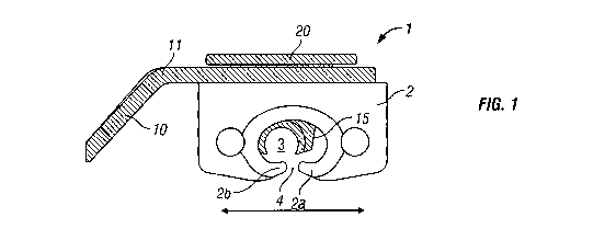
Referring to the drawings and initially to figures 1 to 5, there is shown a
safety line
traveller 1 comprising a body 2 arranged to be held captive on and run along a
safety line.
The body is provided with an interior space 3 for receiving the safety line
and a slot 4
defined between a pair of edges 2a 2b running in the longitudinal direction of
the safety
line. The slot extends to the exterior of the traveller. As shown in figure 2
the safety line is
CA 02770846 2012-02-10
WO 2011/027109 PCT/GB2010/001653
-9-
supported by intermediate supports 6 which have a cylindrical portion 7
defining a
cylindrical channel 5 through which the safety line passes. A narrow section 8
of the
support 6 extends from the cylindrical portion 7 to a distal anchor portion of
the support
(not shown) enabling the support to be secured to a support post or directly
to a structure
(usually by means of a threaded bolt or other mechanical fixing. Such supports
are well
known in the art.
As can be seen from the drawings, the slot 4 defined between the pair of edges
2a 2b
running in the longitudinal direction of the safety line is of a gap
sufficiently large to allow
the narrow section 8 to pass through the gap as the traveller moves past the
intermediate
support. However the slot 4 defined between the pair of edges 2a 2b is
sufficiently small
so as not to allow the safety line to pass out of the interior space 3 of the
body when the
traveller is moving along the safety line between the intermediate supports.
Consequently
it can be seen that it is important to align the slot 4 defined between the
pair of edges 2a 2b
accurately with the narrow section 8 of the support 6 in the absence of any
other means of
correcting for mis-alignment.
In the arrangement of figures 1 to 5, the lanyard or other means of attachment
to the user is
connected, typically by a karabiner, attached to an eye 10 provided in an arm
11 extending
from the body 2.
Positioned in the body 2 at the interior space 3 is a safety line locating
shuttle 15 that is
able to move in a predetermined manner in the direction of separation of the
pair of edges
2a 2b. Typically the safety line locating shuttle 15 is capable of moving, in
reciprocating
motion, between extreme positions across at least a part of the slot 4 defined
between the
pair of edges 2a 2b. This may be achieved for example by the shuttle 15 being
mounted to
be slidable along a slider pin 16 mounted in the body 2 and extending across
the interior
space 3 of the body 2. The safety line locating shuttle 15 is provided with an
arcuate
recess 14 in a lower portion arranged to locate with the safety line, or the
cylindrical head 7
of the intermediate support, depending upon whether the shuttle is passing the
intermediate
support 6 or along a length of the safety line.
CA 02770846 2012-02-10
WO 2011/027109 PCT/GB2010/001653
-10-
As shown in figure 2, the shuttle is located centrally over the slot 4 as it
passes the
intermediate support 6 such that the narrow section 8 can move through the
slot 4. This is
because the traveller 1 is in its neutral position as it is dragged past the
support 6, in which
the traveller is orientated horizontally (i.e. the slot is horizontal).
As shown in figure 3, if the traveller 1 is dragged past the intermediate
support 6 in
circumstances in which the lanyard is pulling downwardly on the arm 11 (arrow
A), the
traveller body 2 rotates such that the slot 8 is no longer orientated
horizontally. Due to the
nature of its construction, when this occurs, the shuttle 15 becomes re-
orientated by
moving upwardly and to the right in the figure to its extreme right position.
This permits
the narrow part 8 of the intermediate support 6 to pass through the slot 4.
Effectively the
point of location of the cylindrical tube 7 in the body of the traveller 2 is
moved to
compensate for the re-orientation of the traveller body about the axis of the
safety line or
the cylindrical tube 7 of the support 6.
Conversely, and as shown in figure 4 if the traveller I is dragged past the
intermediate
support 6 in circumstances in which the lanyard is pulling upwardly on the arm
11 (arrow
B), the traveller body 2 rotates such that the slot 8 is no longer orientated
horizontally.
Due to the nature of its construction, when this occurs, the shuttle 15
becomes re-orientated
by moving upwardly and to the left in the figure to its extreme left position.
This permits
the narrow part 8 of the intermediate support 6 to pass through the slot 4.
The slot 4 can therefore be dimensioned to permit the narrow section 8 of the
support to
pass in a wide degree of differing angular orientations, whilst ensuring that
the safety line
(on approach to, or exit from the support) or the support tube 7 is accurately
held in the
appropriate position with respect to the traveller body.
In the embodiment shown, the shuttle 15 is attached to the arm 11, such that
as the shuttle
15 moves so too does the arm 11. The arm is however rotatable through at least
360
degrees with respect to the shuttle 15. A mounting spindle 17 passes through a
circular
aperture 19 in the arm 11 to be received in a bore 18 in the upper surface of
the shuttle 15.
The spindle 19 is provided with a cap 20. The slider pin 16 passes through the
spindle 19.
CA 02770846 2012-02-10
WO 2011/027109 PCT/GB2010/001653
-11-
The arm in most cases will only be required to be rotatable with respect to
the shuttle 15 or
traveller body 2 through 180 degrees. This will enable the arm to be used on
either
opposed side of the safety line.
Referring now to the traveller arrangement shown in figures 6 to 9, the
traveller 101
comprises a traveller body 102 arranged to be held captive on and run along a
safety line.
The body 102 is provided with an interior space 103 for receiving the safety
line and a slot
104 defined between a pair of edges 102a 102b running in the longitudinal
direction of the
safety line, As shown in figure 7 the safety line is supported by intermediate
supports 6
which have a cylindrical tube portion 7 defining a cylindrical channel 5
through which the
safety line passes. A narrow section 8 of the support 6 extends from the
cylindrical portion
7 to a distal anchor portion of the support (not shown) enabling the support
to be secured to
a support post or directly to a structure (usually by means of a threaded bolt
or other
mechanical fixing. Such supports are well known in the art.
As in respect of the previously described embodiment, the users lanyard (or
other means of
attachment to the user) is connected, typically by a karabiner, attached to an
eye 110
provided in an arm 111 extending from the body 2.
In this embodiment the slot 104 is defined between the pair of edges 102a 102b
each
provided on a separate pivotally movable paddle or element 102c 102d. Each
paddle or
element 102c 102d is mounted to an upper body element 102e by means of a
separate pivot
fixing 126 127. In a `normal' configuration as shown in figure 7, the paddles
are arranged
to be orientated under gravity such that a turning moment arises about the
pivot fixings 126
127 to urge the shoulders 102f 102g into engagement with reaction surfaces
provided on
the upper body element 102e. In an alternative embodiment biasing means (such
as spring
elements) may be used to bias the paddle elements 102c 102d to a normal
position (which
may be the position shown in figure 7 or another `home position).
In this orientation (as shown in figure 6/7) the slot 104 between edges 102a
102b is
sufficiently large to allow the narrow section 8 to pass through the gap as
the traveller
moves past the intermediate support. However the slot 104 defined between the
pair of
CA 02770846 2012-02-10
WO 2011/027109 PCT/GB2010/001653
-12-
edges 102a 102b is sufficiently small so as not to allow the safety line to
pass out of the
interior space 103 of the body when the traveller is moving along the safety
line between
the intermediate supports. Consequently it can be seen that it is important to
align the slot
4 defined between the pair of edges 2a 2b accurately with the narrow section 8
of the
support 6 in the absence of any other means of correcting for mis-alignment.
However in this embodiment, it is possible for the paddles 102c 102d to
pivotally re-
orientate from the normal position when approaching or passing the
intermediate support 6
in the event that the traveller has been forced to a rotationally re-oriented
position with
respect to the safety line or the cylindrical tube 7 of the intermediate
support.
As shown in figure 8, if the traveller 101 is dragged past the intermediate
support 6 in
circumstances in which the lanyard is pulling downwardly on the arm 111 (arrow
A), the
traveller body 102 rotates such that the slot 104 is no longer orientated
horizontally. Due
to the nature of its construction, particularly the provision of the inclined
lower surface
102h of paddle 102c, when approaching the support 6, the paddle 102c becomes
re-
orientated as a result of contact between surface 102h and the leading edge of
the narrow
section 8 of the support, so as to displace the paddle 102c such that its edge
102b rotates
upwardly toward the space 103. This permits the narrow part 8 of the
intermediate support
6 to pass through the re configured slot 104. Effectively the slot 104 is re-
configured by
the pivoting of paddle 102c in order to compensate for the re-orientation of
the traveller
body about the axis of the safety line or the cylindrical tube 7 of the
support 6.
Conversely, and as shown in figure 9 if the traveller 101 is dragged past the
intermediate
support 6 in circumstances in which the lanyard is pulling upwardly on the arm
111 (arrow
B), the traveller body 2 rotates such that the slot 104 is no longer
orientated horizontally.
Due to the nature of its construction, when this occurs, the paddle 102d
becomes re-
orientated as a result of contact between surface 102j and the leading edge of
the narrow
section 8 of the support, so as to displace the paddle 102d such that its edge
102a rotates
upwardly toward the space 103. This permits the narrow part 8 of the
intermediate support
6 to pass through the re configured slot 104. Effectively the slot 104 is re-
configured and
altered in spacing distance, by the pivoting of paddle 102c in order to
compensate for the
CA 02770846 2012-02-10
WO 2011/027109 PCT/GB2010/001653
-13-
re-orientation of the traveller body about the axis of the safety line or the
cylindrical tube 7
of the support 6.
In both extremes of reconfiguration of the paddles, the slot 104 is maintained
at a
dimension at which the tube 7 and/or the safety line cannot pass through
The traveller 101 can therefore be configured automatically permit the narrow
section 8 of
the support to pass in a wide degree of differing angular orientations of the
traveller.
In this embodiment also the arm is however rotatable through at least 180
degrees (even
possibly through 360degrees) being mounted via a spindle attached to cap 320
which
extends through a circular mounting aperture in the arm 311 to be received in
a bore in the
valve body. This enables 180 or 360 degrees rotation with respect to the valve
body
enabling the device to be adapted for use on either of the opposed sides of a
safety line.
Referring now to the embodiment of figure 10, there is shown a safety line
traveller that
combines the features of the re-orientatable, slidable shuttle 15 of the first
embodiment
with the re-orientatable paddles of the second embodiment. In figure 10 the
shuttle 315 is
shown and is mounted to the main traveller body 302e by means of a slider pin
extending
across the traveller upper body 302e. The pin is not shown in figure 10, but
it will be
appreciated that the shuttle 315 is provided with a bore through which the
slider pin
extends such that the shuttle can slide across the body from one extreme
position to
another. The slot 304 is defined between the edges of the paddles 302c 302d,
which are
both pivotally6 mounted to the upper traveller body 302e by means of the pivot
fixings 326
327.
The embodiment of figure 10 having both the shuttle feature and the re-
orientatable
paddles provides that the arrangement is technically versatile and highly
effective in
smoothly passing by an intermediate support. The embodiment of figure 10 also
has an
attachment eye 310 in the arm 311 that is oriented to define a pass through
direction which
is in the same general direction as the direction in which the safety line
extends (i.e. in the
CA 02770846 2012-02-10
WO 2011/027109 PCT/GB2010/001653
-14-
same general direction of travel as the direction of travel of the traveller).
This provides
technical advantage.
Referring now to the embodiment of figures 11 to 16, the traveller is
generally similar to
the embodiment of figure 10 except that the arm 311 is provided with an eye
311 extending
from the upper surface to the lower surface of the arm. Figure 11 shows the
shuttle 315
mounted to the upper traveller body 302e by means of a slider pin 316
extending across the
traveller upper body 302e. The shuttle 315 is provided with a bore through
which the
slider pin extends such that the shuttle can slide across the body from one
extreme position
to another. The slot 304 is defined between the edges of the paddles 302c
302d, which are
both pivotally mounted by means of pivot fixings 326 to the upper traveller
body 302e.
In the embodiment shown in figures 10 to 16 and as clearly shown in figure 11,
the shuttle
315 is attached to the arm 311, such that as the shuttle 315 moves so too does
the arm 311.
The arm is however rotatable through at least 180 degrees (typically fully 360
degrees)
with respect to the shuttle 315. A mounting spindle 317 passes through a
circular aperture
319 in the arm 311 to be received in a blind bore 18 in the upper surface of
the shuttle 15.
The spindle 19 is provided with a cap 320. The slider pin 316 passes through
the spindle
319. The arm 311 in most cases will only be required to be rotatable with
respect to the
shuttle 15 or traveller body 2 through 180 degrees. This will enable the arm
to be used on
either opposed side of the safety line. It should be noted that, in the
embodiment shown,
the arm 311 is inclined outwardly and downwardly from the traveller to a
degree to cross
the level of the safety line. This ensures that when the traveller is in use
the arm 311 when
rotated will only do so until it clashes with the safety line or intermediate
support (as
shown most clearly in figure 16). The arm therefore extends outwardly and in a
transverse
direction to pass across the level of the safety line position in the
traveller 301.
As shown in figure 12, the shuttle 315 is located centrally over the slot 304
as it passes the
intermediate support 6 such that the narrow section 8 can move through the
slot 304. This
is because the traveller 301 is in its neutral position as it is dragged past
the support 6, in
which the traveller is orientated horizontally (i.e. the slot is horizontal).
In a'normal'
configuration as shown in figure 12, the paddles 302c 302d are arranged to be
orientated
CA 02770846 2012-02-10
WO 2011/027109 PCT/GB2010/001653
-15-
under gravity such that a turning moment arises about the pivot fixings 326
327 to urge the
shoulders 302f 302g into engagement with reaction surfaces provided on the
upper body
element 302e. In this orientation the slot 304 between edges 302a 302b is
sufficiently
large to allow the narrow section 8 to pass through the gap as the traveller
moves past the
intermediate support.
As shown in figure 13, if the traveller 301 is dragged past the intermediate
support 6 in
circumstances in which the lanyard is pulling downwardly on the arm 311 (arrow
A), the
traveller rotates such that the slot 308 is no longer orientated horizontally.
As a result, the
shuttle 315 becomes re-orientated by moving upwardly and to the right in the
figure to its
extreme right position. Simultaneously, when approaching the support 6, the
paddle 302c
becomes re-orientated as a result of contact between surface 302h and the
leading edge of
the narrow section 8 of the support, so as to displace the paddle 302c such
that its edge
302b rotates upwardly toward the shuttle 315. This permits the narrow part 8
of the
intermediate support 6 to pass through the re configured slot 304. This
permits the narrow
part 8 of the intermediate support 6 to pass through the slot 304.
Figure 14 shows the reverse situation in which the traveller 301 is dragged
past the
intermediate support 6 in circumstances in which the lanyard is pulling
upwardly on the
arm 311 (arrow B). The shuttle 315 becomes re-orientated by moving upwardly
and to the
left in the figure to its extreme left position. Simultaneously, when
approaching the
support 6, the paddle 302d becomes re-orientated as a result of contact
between surface
302j and the leading edge of the narrow section 8 of the support, so as to
displace the
paddle 302d such that its edge 302a rotates upwardly toward the shuttle 315.
This permits
the narrow part 8 of the intermediate support 6 to pass through the slot 304.
The combined use of the re-orientatable paddles to define the slot and the
shuttle 315
provides maximum benefits in terms of use.
Referring now to figures 17 to 28, there is shown a further embodiment of
traveller that
embodies the re-orientatable paddles 402c 402d and also the shuttle 415 and
includes
further functionality in that one of the paddles 402d can be moved from its
`normal'
CA 02770846 2012-02-10
WO 2011/027109 PCT/GB2010/001653
-16-
position to an open position in which the slot 404 defined by the spacing
between the edges
402a 402b of the paddles is large enough for the diameter of the safety line
to pass through.
For safety reasons the paddle 402d can only be moved from the normal position
to the
open position when a pair of actuator buttons 431 432 are pressed
simultaneously into the
traveller upper body 402e.
Furthermore the arrangement is such that the pair of actuator buttons 431 432
can only be
pressed simultaneously into the traveller upper body 402e when the shuttle 415
is in a
specific position with respect to the traveller upper body 402e. This ensures
that the safety
line can only be received into the shuttle when the shuttle 415 is correctly
aligned to
receive the safety line and prevents the safety line being incorrectly
inserted via the
between the edges 402a 402b of the paddles into a space to one side or the
other of the
shuttle 415.
A further feature is that the button actuators 431 432 are biased outwardly by
means of
springs 433 434 such that when released they revert to their position
projecting outwardly
from the upper traveller body 402e. In moving back to that position, the
paddle 402d is
urged back to the normal position in which the gap between the paddle edges
402a 402b is
sufficiently small too prevent the safety line from passing out of the
traveller 401 via the
slot 404.
In figures 17 and 18 the shuttle 415 is shown in its intermediate position
directly opposite
the slot. The shuttle 415 is freely movable across from one side of the slot
404 to the other
as in the earlier described embodiments. The shuttle 415 travels on the slider
pin 416
guided in a channel 435 in the upper traveller body 402e. The button actuators
431 432 are
biased outwardly by the springs 433 434 and project outwardly from the
traveller upper
body 402e on opposed sides of the traveller 401. The button actuators slide in
respective
recesses 441 in upper traveller body 402e and have guide slots 439 which
accommodate a
fixed guide pin 440 in order to guide the travel of the respective button
actuator.
The shuttle 415 is provided at opposed sides with respective recess formations
436 which
are shaped and dimensioned to receive complementary engagement projections 437
CA 02770846 2012-02-10
WO 2011/027109 PCT/GB2010/001653
-17-
provided on the button actuators 431 432. The alignment of the recess
formations 436 of
the shuttle 415 with the projections 437 of the button actuators 431 432 only
occurs when
the shuttle 415 is slid to a specific position with respect to the upper body
402e and slot
404 (i.e. the spacing between the edges 402a 402b of the paddles 402c 402d).
In the
embodiment shown the alignment position is designed to be at the maximum
extent of
travel of the shuttle 415 to one side of the slot 404. This is because the
position is easy for
the user to locate. In this specific position the button actuators 431 432 can
be
simultaneously pressed into the traveller body, acting against the biasing
springs 433 434,
such that the projections 437 of the button actuators 431 432 become engaged
in the recess
formations 436 of the shuttle. In this position, whilst the user keeps the
button actuators
depressed, the shuttle cannot be moved from its located position. This is
important
because the paddle 402d is now caused to move to an open position in which the
slot 404
defined by the spacing between the edges 402a 402b of the paddles is large
enough for the
diameter of the safety line to pass through. The arrangement ensures that the
paddle 402d
can only be opened to accommodate the insertion of the safety line when the
shuttle 415 is
correctly located in the correct defined receiving position. The risk of the
safety line being
received into the traveller but incorrectly located on one side or the other
of the shuttle 415
is therefore ameliorated.
In the normal, closed position before and after receiving the safety line into
the traveller
401, the paddle 402c 402d are in the position shown in figure 22. in this
situation, when in
use, the paddles are free to pivotally re-orientate about the pivot fixings
426 42, in a similar
manner to the earlier described embodiments, to best accommodate passage
through the
safety line intermediate supports, the paddle. In this respect it should be
remembered that
in use the paddles can only pivot upwardly from the normal position in
response to
operating forces. Gravity (or other biasing means) normally biases the paddles
to the
`normal' position shown in figure 22. In this embodiment paddle 402d is
prevented from
rotating on the pivot fixing 427 (counter clockwise as shown in the view of
figure 22) to an
open position, by means of two spaced upstanding projections 402g which abut
against the
forward edges 431 a 432a of a respective actuator button 431 432.
CA 02770846 2012-02-10
WO 2011/027109 PCT/GB2010/001653
-18-
The button actuators at their forward edge 431a 432a are provided with
respective slots
445 spaced outwardly of the spring receiving cavities 451 of the button
actuators 431 432.
The upper traveller body 402e is provided with correspondingly aligned slots
449. When
the button actuators 431 432 are not pushed fully in, the slots 445 do not
align up with the
slots 449 in the upper body an the upstanding projections 402g and the paddle
402d is
thereby prevented from rotating on the pivot fixing 427 (counter clockwise as
shown in the
view of figure 22) to an open position, because the two spaced upstanding
projections 402g
abutting against the forward edges 431 a 432a of a respective actuator button
431 432.
However, when the button actuators 431 432 are pushed fully in, the slots 445
align with
the slots 449 in the upper body and the upstanding projections 402g. This
permits the
paddle 402d to rotate counter-clockwise (arrow X in figure 22) to the fully
open position as
shown in figure 24. In constructed embodiments it has been found that paddle
rotation of
approximately 15 degrees has been sufficient to open the gap 404 (defined by
the spacing
between the edges 402a 402b of the paddles) the required degree to permit the
safety line
to be loaded. In the fully open position the paddle 402d abuts against the
body 402e to
prevent over opening of the gap 404. Once the safety line is loaded into the
shuttle, the
paddle 402d can be reverted to the closed, normal, position (i.e. back to the
position of
figure 22). Releasing pressure on the button actuators 431 432 causes the
springs 433 434
to move the actuator buttons outwardly to return to their `home' position in
which the slots
445 do not align up with the slots 449 in the upper body and the upstanding
projections
402g and the paddle 402d is thereby prevented from rotating counter-clockwise
on the
pivot fixing 427 to the open position.
In certain embodiments, the paddle 402d may be caused to return from the open
position to
the closed position automatically as the actuator buttons 431 432 move
outwardly to return
to their `home' position. This may be achieved for example by having co-acting
inclined
surfaces 445a on the slots 445 of the button actuators for engagement with the
projections
402g of the paddle 402d. As the actuator buttons 431 432 move outwardly to
return to
their `home' position the inclined surface 445a acts against the projections
402g of the
paddle 402d to urge the paddle from the position shown in figure 25 to the
position shown
in figure 27.
CA 02770846 2012-02-10
WO 2011/027109 PCT/GB2010/001653
-19-
A further embodiment of a traveller 501 in accordance with a preferred
realisation of the
invention is shown in figures 29 to 37. In this embodiment a shuttle 515
operable in the
same manner as the previously described embodiments is provided and the slot
is defined
between re-orientatable paddles 502c 502d. In this instance the paddles are
not pivotally
mounted, so as to re-orientate by means of pivotal movement, but rather slide
bodily to lift
upwardly and fall downwardly with respect to the main traveller body 502e
between a
lowered position and a lifted position as the traveller 501 passes a
respective intermediate
support.
As shown in figure 32, the shuttle 515 is located centrally over the slot 504
as it passes the
intermediate support 6 such that the narrow section 8 can move through the
slot 504. This
is because the traveller 501 is in its neutral position as it is dragged past
the support 6, in
which the traveller is orientated horizontally (i.e. the slot is horizontal).
In a `normal'
configuration as shown in figure 29, the paddles 502c 502d are arranged to be
orientated
under gravity to rest in their lowered position (corresponding to the position
shown in
figure 29). In this orientation the slot 504 between edges 502a 502b is
sufficiently large to
allow the narrow section 8 to pass through the gap as the traveller moves past
the
intermediate support.
As shown in figure 33, if the traveller 501 is dragged past the intermediate
support 6 in
circumstances in which the lanyard is pulling downwardly on the arm 511 (arrow
A), the
traveller rotates such that the slot 508 is no longer orientated horizontally.
As a result, the
shuttle 515 becomes re-orientated by moving upwardly and to the left in the
figure to its
extreme left position. Simultaneously, when approaching the support 6, the
paddle 502d
becomes re-orientated, being lifted upwardly from its lowered at rest position
as a result of
contact between surface 502j and the leading edge of the narrow section 8 of
the support,
so as to displace the paddle 502d upwardly toward the shuttle 515. This
permits the narrow
part 8 of the intermediate support 6 to pass through there configured slot
504.
Figure 34 shows the reverse situation in which the traveller 501 is dragged
past the
intermediate support 6 in circumstances in which the lanyard is pulling
upwardly on the
CA 02770846 2012-02-10
WO 2011/027109 PCT/GB2010/001653
-20-
arm 511 (arrow B). The shuttle 515 becomes re-orientated, by moving upwardly
and to the
right in the figure to its extreme right position. Simultaneously, when
approaching the
support 6, the paddle 502c becomes re-orientated, being lifted upwardly from
its lowered
at rest position as a result of contact between surface 502h and the leading
edge of the
narrow section 8 of the support, so as to displace the paddle 502c upwardly
toward the
shuttle 515. This permits the narrow part 8 of the intermediate support 6 to
pass through
the re configured slot 504.
The combined use of the re-orientatable paddles to define the slot and the
shuttle 315
provides maximum benefits in terms of use. Paddles that can slide to lift and
fall bodily
with respect to the traveller body rather than being pivotally mounted are
believed to
improve robustness and be less likely to fail in the event of a fall.
The shuttle 515 is attached to the load arm 511, such that as the shuttle 315
moves across
the slot, then so too does the arm 511. The load arm 51 is however rotatable
through fully
360 degrees with respect to the shuttle 515 and therefore also rotatable with
respect to the
main traveller body 502e. A mounting spindle 517 comprising the shuttle passes
through a
circular aperture 519 in the arm 511. The spindle 519 is provided with a cap
520. The
slider pin 516 passes through the spindle 519. The rotary mounting of the arm
511 with
respect to the shuttle 515 and the main traveller body 502e enables the arm
511 to be used
on either opposed side of the safety line. It should be noted that, in the
embodiment
shown, the arm 511 has a karabiner attachment bracket 510, which is positioned
outwardly
and downwardly from the traveller to a degree to cross the level of the safety
line. This
ensures that when the traveller is in use the load arm 511, when rotated, will
only do so
until it clashes with the safety line or intermediate support. The arm
therefore extends
outwardly and in a transverse direction to pass across the level of the safety
line position in
the traveller 501.
In this embodiment, the shuttle 515 is mounted to the upper traveller body
502e by means
of a slider pin 516 extending across the traveller upper body 502e. The
shuttle 515 is
provided with a channel through which the slider pin 516 extends such that the
shuttle can
slide across the body from one extreme position to another (the opposed
extreme shuttle
CA 02770846 2012-02-10
WO 2011/027109 PCT/GB2010/001653
-21-
positions are shown in figures 30 and 31 respectively). The slot 504 is
defined between the
edges 502a 502b of the paddles 502c 502d, which are both slidably mounted with
respect
to the upper traveller body 502e.
The paddles 502c 502d are both slidably mounted with respect to the upper
traveller body
502e in respective guide channels in the main traveller body 502e. The paddles
slide in a
transverse direction to the direction of movement of the shuttle with respect
to the main
traveller body 502. An exemplary paddle 502d is shown in figure 38. Each
paddle has a
stem portion 502f 502g which is constrained to move upwardly and downwardly in
the
guide channel in the main traveller body 502e, and a transverse portion 5021
502m which
extends away from the respective stem portion terminating at the paddle tips
502a 502b
which are spaced to define the slot 504 between the paddle elements. The stem
portions
502f 502g of the paddles are each provided with an upwardly orientated slot
571 through
which the slider pin 516 passes. In the lowered position resting under
gravity, both of the
paddle elements 502c 502d are at rest suspended from the slider pin 16, and
prevented
from becoming separated from the main traveller body by the slider pin 516
passing
through the slot 571 in the stem portion of the respective paddles 502c 502d.
This position
is shown in figure 29.
The `in operation' upward limit of sliding movement of paddle 502d is defined
by an
abutment shoulder 573 carried by the main traveller body 502e. The paddle 502d
abutting
the shoulder 573 in the uppermost operational position of the paddle 502d is
shown in
figure 31. In this position the upper surface of the stem portion 502g of the
paddle 502d
lies flush with the upper surface of the main traveller body 502c and abuts
against the
underside surface of the lower arm element 511 a.
The `in operation' upward limit of sliding movement of paddle 502c is defined
by the
position in which the upper surface of the stem portion 502f of the paddle
502c lies flush
with the upper surface of the main traveller body 502e and abuts against the
underside
surface of the lower arm element 511 a. The paddle 502c abutting the underside
surface of
the lower arm element 511a in the uppermost operational position of the paddle
502c is
shown in figure 30.
CA 02770846 2012-02-10
WO 2011/027109 PCT/GB2010/001653
-22-
In all the operational positions of the shuttle 515 and paddles 502c 502d when
the
karabiner is attached to the attachment 510, the slot gap 504 between the
edges of the
paddles 502c 502d is maintained sufficiently small that the safety line to
which the
traveller is secured cannot pass out of the traveller body 502.
In order to permit the traveller 501 to be secured to the safety line or
removed from the
safety line, the components of the traveller 501 must be configured in a
specific orientation
in order to enable the paddle 502c to be raised to a line-mounting/de-mounting
position,
which is raised above its `in operation' upward limit. This position is shown
in figure 37,
in which the safety line can pass through the expanded gap 504 between the
paddle 502c
502d edges into or out of the shuttle 515. An advantageous feature of the
arrangement is
that in the line loading position, the karabiner cannot be secured to the arm
attachment 510.
Conversely, the arrangement cannot be configured for line loading or unloading
whilst the
karabiner remains attached to the attachment bracket 510.
In order to achieve this the lower arm element 511 a is provided with an
attachment bracket
510a which is slidable linearly with respect to the upper arm element 511 (and
bracket
portion 510) between a position in which karabiner receiving apertures 581 on
the
attachment brackets 510a 510 are coaxially aligned (figure 35 and 39) and' a
position in
which the karabiner receiving apertures on the attachment brackets 510a 510
are in
maximum mis-alignment (figure 36). An elongate slot is provided in the lower
arm
element 511 to permit sliding relative to the upper arm element 511 and also
the shuttle
515. As shown in fig 39 the inner attachment bracket 510a is nested within the
outer
attachment bracket 510, each generally being `U' shaped in configuration.
In order to configure the device in the safety line-mounting/de-mounting
position, the
lower arm 511 a must first be moved to the position in which the karabiner
receiving
apertures on the attachment brackets 510a 510 are in maximum mis-alignment
(figure 36).
In this position, the slot in the lower arm 511a directly overlies the guide
channel in the
traveller main body 502e, which guides the stem 502f of the paddle 502c. In
this position
the slot in the lower arm 511 a additionally lies directly under an aperture
576 in the upper
CA 02770846 2012-02-10
WO 2011/027109 PCT/GB2010/001653
-23-
arm 511. The slot in the lower arm 511 a and the aperture 576 in the upper arm
511 are both
shaped and dimensioned so as to permit the stem 502f of the paddle 502c to
pass upwardly
through the arms 511 and 511 a, to the raised line-mounting/de-mounting
position which is
lifted above the `in operation' upward limit of the paddle 502c. This position
is shown in
figure 37. It should be noted that in the raised line-mounting/de-mounting
position shown
in figure 37, the paddle 502c abuts against a shoulder 579 provided on the
traveller main
body 502e. The shoulder 579 is provided at a raised level with respect to the
shoulder 573.
Also, the paddle 502c is provided with an aperture 580 configured to
accommodate a
peripheral edge of the shuttle 515 enabling the paddle 502c to be raised to
the raised line-
mounting/de-mounting position.
As mentioned earlier, an advantage of this embodiment of the invention is that
the paddles
are not pivotally mounted, which reduces components and also improves
robustness of
construction. Additionally, the traveller can only be configured in the raised
line-
mounting/de-mounting position when the attachment brackets 510a 510 are in
maximum
mis-alignment (figure 36). This means that the traveller cannot be de-mounted
from the
line when the karabiner is attached. A further advantage of the arrangement is
that the
safety line can only be correctly inserted into the receiving saddle of the
shuttle 515 and
cannot be inserted in error into another portion of the internal cavity of the
traveller body
502. This is because access to other portions the internal cavity of the
traveller body 502 is
obscured by the position of the shuttle 515 and paddles 502c 502d when
orientated in the
mounting/de-mounting position.
Effectively, the slot 504 is re-configurable between an open condition in
which the slot
dimension is of a first size for enabling mounting/de-mounting with respect to
a safety line;
and a closed condition, locked by the lower arm 511 a, in which the slot 504
remains, but at
a smaller size to ensure the traveller remains mounted on the safety line. In
the closed
condition the opposed slot edges are still moveable freely movable relative to
one another
to reconfigure the slot giving the improved flexibility to pass the safety
line intermediate
supports. However the range of slot sizes over the range of slot edge movement
in the
closed condition is such that the traveller cannot disengage from the safety
line via the slot
504.
CA 02770846 2012-02-10
WO 2011/027109 PCT/GB2010/001653
-24-
The traveller of the invention can be used effectively with standard types of
intermediate
support currently in use. No special deflectors or modifications need to be
made to
existing standard types of intermediate support.