Note : Les descriptions sont présentées dans la langue officielle dans laquelle elles ont été soumises.
CA 02771935 2012-02-23
WO 2011/023672 PCT/EP2010/062289
HIGH EFFICIENCY REGULATED CHARGE PUMP
FIELD
[0001] The disclosure relates to high efficiency regulated electronic charge
pumps.
BACKGROUND INFORMATION
[0002] Charge pumps are an essential power conversion building block that
finds wide
application in mobile electronic devices. Charge pumps are key parts of
display driver ICs, LED
backlight drivers and flash memory. For many rich-media mobile devices, the
display and
backlight driver can dominate the power consumption; often more than half of
the average power
is spent through charge pumps. Improving the efficiency of charge pumps has
been a
semiconductor industry focus for many years given its direct impact on battery
life of mobile
devices.
[0003] Charge pumps constitute a class of DC-DC converters that use capacitors
as the
core energy conduction and storage medium; another popular class of DC-DC
conversion relies
on inductive components. DC-DC conversion with inductive components is ideal
for many
applications and can reach very high efficiency at high loads; however, these
converters tend to do
less well (efficiency, cost, size) at light loading. Light loads generally
will require larger, more
expensive inductors; in contrast, lighter load applications require only
smaller and lower cost
capacitors. For some light load applications (e.g. displays), charge pumps are
more cost-effective,
smaller and easier to design than inductive DC-DC converters.
[0004] Charge pumps that multiply a source voltage by integer or fractional
values are
well known in the art. With available technology, unregulated multiplying
charge pumps can be
made exceptionally efficient (>99%) in certain regimes of operation. However,
if the source
voltage is unregulated, the output will not be regulated either.
[0005] The voltage and effective impedance of a battery can vary substantially
with its
charge state. To create a low impedance power supply voltage from a battery,
the combination of
1
CA 02771935 2012-02-23
WO 2011/023672 PCT/EP2010/062289
a charge pump and voltage regulator is often used. In some applications, the
battery voltage is
first regulated and then multiplied; in other applications the battery voltage
is multiplied and then
regulated. In still other implementations, the multiplier is run at a varying
clock rate to control the
effective charge (or current) delivered to a load; as part of a closed loop
regulation, the charge
pump can be seen as an ideal voltage source at the open circuit voltage
prescribed by the topology
of the multiplier with a variable output impedance (proportional to clock
rate) that can be made
part of a feedback loop to achieve regulation.
[0006] In most of the charge pump and regulator combinations, there is a
linear regulator
function somewhere in the design. Linear regulation has the downside of
dissipating power (and
dropping voltage); the unavoidable dissipation is equal to the current
supplied by the regulator
times the voltage drop across the regulator. It is well known in the art to
take the approach of
choosing the lowest input voltage possible to minimize the losses due to
voltage drop across a
linear regulator.
[0007] In many display charge pump applications, a number of different
voltages are
required (e.g. 6 or more to control the gate, source and COM signals of a TFT
LCD). To reduce
cost and board area the number of charge pumps and the components are
minimized to save cost
and by sharing functions (e.g. make a single charge pump which can deliver
multiple output
voltages). Often the accuracy requirements for the voltages are not the same
(e.g. COM voltages
require finer tuning than gate signals, for example).
[0008] The function of regulation is very similar to amplification; a negative
feedback loop
from the output comparing the signal to a stable reference generates a
correction signal to the
output driver. Open loop charge pumps often suffer from high output impedance
or excessive
clock frequencies (which lead to higher quiescent power) to keep impedance
reasonable. Negative
feedback loops can be added to a natively high impedance output source (such
as a slowly clocked
charge pump) to achieve a much lower output impedance and can be thus
considered as an avenue
for power savings by then enabling the clock frequency of the charge pump to
be reduced
significantly. Analog amplification with an operational amplifier will
typically consume some static
power; hence a tradeoff exists between charge pump clocking frequency and
amplifier power. If
2
CA 02771935 2012-02-23
WO 2011/023672 PCT/EP2010/062289
amplifier power. If the reduction in charge pump clocking power is much larger
than the increase
due to the addition of an amplifier, then the overall solution can reach a
lower power while
meeting similar (if not better) specifications for regulation (e.g. output
impedance, stability,
reliability, insensitivity to manufacturing variations, etc.) since closed
loop regulation is generally
consider superior to open loop regulation. If the amplification power costs is
low enough, there
are a host of benefits from closing the loop.
[0009] For regulating high voltages with a high voltage amplifier, some
quiescent bias
current is typically drawn from high voltage power rails in the output stage
of a high voltage
amplifier. Amplifiers constructed from high voltage devices tend to be large,
slow and inefficient,
often requiring more bias current to offset the device limitations. Overall it
is difficult to build a
high voltage amplifier with good characteristics and low power, compared to
low voltage
amplifiers where the devices and costs are much lower. And if the voltage
supply rails of the
operational amplifier are significantly different from the output voltage,
such an amplifier will
incur the same power loss as that seen in linear regulators (equal to the
voltage drop times the
sourced current) which will negatively impact the efficiency. Any approach
that includes negative
feedback regulation of high voltages needs to consider such issues.
[0010] Analog amplifiers are broadly categorized into classes - a Class AB,
for example, is
a push-pull output configuration. To achieve greater efficiency, efficient DC-
DC power supply
ideas have been adopted by amplifier designers. Many of these advanced high
efficiency amplifiers
make use of inductors, at sometimes significant expense and size increase
compared to the linear
(e.g. Class AB) equivalent. Examples are Class D (inductor in the output) or
Class H
(continuously variable output supply rails from a typically inductive based DC-
AC converter).
Class G amplification (multi-rail) is also a possible architecture, but is
often prohibitively complex
(more pins, components, board area and quiescent current from HV sources) that
it negates the
power advantage of closed loop & low frequency charge pumps. To avoid
inductors (which have
difficulty reaching high efficiency, low cost and small board space at light
power loads) a new
topology is needed that integrates advanced amplification (e.g. a variable
rail voltage or multi-rail)
3
CA 02771935 2012-02-23
WO 2011/023672 PCT/EP2010/062289
with charge pumps without incurring the disadvantages of the common approaches
available to
those skilled in the art.
[0011] The charge pump and regulation topology described herein addresses the
limitations of conventional combined charge pump and regulation circuits by
using a single low
voltage operational amplifier to provide closed loop low impedance accurate
voltage generation
for a number of output voltages using a high efficiency "class G" amplifier
topology integrated
with a Dickson charge pump.
SUMMARY
[0012] A regulating charge pump circuit that uses a single low voltage
operational
amplifier to create multiple high output voltages is disclosed.
[0013] A regulating charge pump circuit that substantially lowers the charge
pump
switching frequency to achieve a given output impedance is disclosed.
[0014] A regulating charge pump circuit that does highly efficient multi-rail
class-G
amplification is disclosed.
[0015] A regulating charge pump circuit that uses charge pump flying
capacitors in the
regulation loop is disclosed.
[0016] A method of operating a regulated charge pump circuit, wherein the
regulated
charge pump circuit comprises a clocked charge pump connected to one or more
pump
capacitors with two terminals each, an amplifier and a feedback network, the
method
comprising:
performing charge pump operations, wherein a charge pump operation switches or
drives
one or more pump capacitor terminals; and
between charge pump operations, performing voltage regulating operations
wherein the
amplifier drives a terminal of at least one pump capacitor and the feedback
network connects to
the another terminal of a pump capacitor to create a desired output voltage
with the feedback
network providing negative feedback from the output voltage to the amplifier.
[0017] The clocked charge pump is a Dickson charge pump.
[0018] The amplifier has lower output voltage range than the desired output
voltage.
4
CA 02771935 2012-02-23
WO 2011/023672 PCT/EP2010/062289
[0019] The regulating charge pump circuit comprises a power source and a
plurality of
pump capacitors that can be alternately connected to a charge pump circuit or
an amplifier with
negative feedback.
[0020] During charge pump operations, each charge pump operation transfers
charge
among the pump capacitors and a power source; and
between charge pump operations, the amplifier is connected to the pump
capacitors
to drive an output voltage using at least one pump capacitor in series with
the amplifier.
[0021] A regulating charge pump circuit, comprising:
one or more pump capacitors with two terminals each,
a charge pump circuit,
an amplifier circuit, wherein both the amplifier circuit and the charge pump
circuit
can control one or more terminals of the pump capacitors,
a feedback network,
an output switch, and
an output terminal connected to a stabilizing capacitor,
wherein the output switch connects the output terminal and the stabilizing
capacitor to one terminal of a pump capacitor while the amplifier controls one
or more alternative
terminals of the pump capacitors and the feedback network is connected to
provide negative
feedback from the output terminal to the amplifier.
[0022] The charge pump is a Dickson charge pump.
[0023] The amplifier is a low voltage amplifier with insufficient output
voltage range to
directly drive the output terminal to the desired voltage.
[0024] the feedback network is comprised of switched capacitors.
[0025] Further objects, aspects, and advantages of the present teachings will
be readily
understood after reading the following description with reference to the
drawings and the
appended claims.
CA 02771935 2012-02-23
WO 2011/023672 PCT/EP2010/062289
BRIEF DESCRIPTION OF THE DRAWINGS
[0026] Figure 1 shows a representative prior art schematic of a Dickson charge
pump
implemented with switches.
[0027] Figure 2 shows a representative prior art schematic of a linear
regulator following a
charge pump.
[0028] Figure 3 shows a representative schematic of a multi-rail charge pump
and a class
G amplifier.
[0029] Figure 4 shows a representative schematic of a multi-rail charge pump,
a class G
amplifier and an output de-multiplexor.
[0030] Figure 5 shows a representative schematic of the Dickson charge pump
integrated
with a class G amplifier with an output de-multiplexor.
[0031] Figure 6 shows representative timing waveforms of the regulated charge
pump
shown in Figure 5.
GLOSSARY OF TERMS
[0032] The following abbreviations are utilized in the following description,
which
abbreviations are intended to have the meanings provided as follows:
[0033] AC - alternating current
[0034] CMOS - complementary MOS (both P and N type FETs available)
[0035] COM - common electrode in an LCD device
[0036] DC - direct current
[0037] FET - field effect transistor
[0038] flying capacitor - in a charge pump, a capacitor with both terminals
switched, in
contrast to a stabilizing capacitor
[0039] IC - integrated circuit
[0040] LCD - liquid crystal display
[0041] MOS - metal oxide semiconductor
6
CA 02771935 2012-02-23
WO 2011/023672 PCT/EP2010/062289
[0042] NMOS - N-channel MOS
[0043] PMOS - P-channel MOS
[0044] stabilizing capacitor - in a charge pump, a capacitor used to hold a
nominally
steady voltage with at least one terminal connected to ground or a DC level.
[0045] TFT - thin film transistor
DETAILED DESCRIPTION
[0046] Each of the additional features and teachings disclosed below may be
utilized
separately or in conjunction with other features and teachings to provide
improved charge pumps
and regulators and methods for designing and using the same. Representative
examples, which
examples utilize many of these additional features and teachings both
separately and in
combination, will now be described in further detail with reference to the
attached drawings. This
detailed description is merely intended to teach a person of skill in the art
further details for
practicing preferred aspects of the present teachings and is not intended to
limit the scope of the
claims. Therefore, combinations of features and steps disclosed in the
following detail description
may not be necessary to practice the concepts described herein in the broadest
sense, and are
instead taught merely to particularly describe representative examples of the
present teachings.
[0047] In addition, it is expressly noted that all features disclosed in the
description are
intended to be disclosed separately and independently from each other for the
purpose of original
disclosure, as well as for the purpose of restricting the subject matter
independent of the
compositions of the features in the embodiments and/or the claims. It is also
expressly noted that
all value ranges or indications of groups of entities disclose every possible
intermediate value or
intermediate entity for the purpose of original disclosure, as well as for the
purpose of restricting
the claimed subject matter.
[0048] Figure 1 shows a conventional bipolar Dickson charge pump implemented
with
ideal switches. In operation, the two clock phases phl and ph2 are driven
alternately between
GND and VDD which will as a consequence charge up each of the pump capacitors
102, 103,
104, 105 to integer multiples of the source voltage VDD for the positive
charge pump section
7
CA 02771935 2012-02-23
WO 2011/023672 PCT/EP2010/062289
100. The pump capacitors 107, 108, 109, 110 of the negative charge pump
section 101 are
similarly charged to negative multiples of the source voltage VDD. Two
stabilizing capacitors
106 and 111 are shown to hold the final maximum and minimum voltage outputs
respectively of
the bipolar charge pump. To achieve good efficiency, discrete capacitors (e.g.
multilayer ceramic
capacitors) are often used as much higher capacitance values with lower stray
capacitances (to e.g.
ground) are available compared to typical on-chip capacitors.
[0049] With no load, the Dickson charge pump pump capacitors 102, 103, 104,
105, 107,
108, 109, 110 will settle to integer multiples of the clock signal voltage
rail on successive Dickson
pump capacitors, i.e. the first capacitor in the positive Dickson chain 102
will have VDD across it,
the second 103 will have 2*VDD, the third 104 will have 3*VDD, etc. The first
capacitor in the
negative Dickson chain 107 will have negative VDD across it, the second 108
will have negative
2*VDD, etc. Note that the inclusion of both a positive and negative rail is
not a limitation of the
present invention; single sided charge pumping and regulation is considered
within the scope of
the present teachings.
[0050] Figure 2 shows a representative prior art implementation of a charge
pump 200
combined with a linear regulator 202. The charge pump 200 generates an outer
rail VHVP
stabilized by capacitor 201 to be the source voltage of the linear regulator
202, which then drives
the output VOUT directly drawing power from this outer rail VHVP. When clocked
with no
load, the Dickson charge pump will nominally achieve an output voltage VOUT
equal to 5 times
the input VDD. When the desired VOUT is close to the outer power supply rail
VHVP, the
efficiency loss can be minor. For lower output voltages, however, the voltage
drop in the output
stage of the linear regulator (VHVP - VOUT) creates a significant efficiency
problem.
Furthermore, the output stage of the amplifier will typically require some
static bias current (the
quiescent current of the amplifier) to be drawn from the high voltage rail
VHVP, which is very
"expensive" power in the sense that current pulled from the e.g. 5*VDD outer
rail shown in
Figure 2 dissipates 5 times more power than if that same current was drawn
from VDD directly.
[0051] Figure 3 shows a possible combination of a multi-rail charge pump 301
with a class
G amplifier 303 to achieve higher efficiency. In operation, the multi-rail
charge pump 301 using
8
CA 02771935 2012-02-23
WO 2011/023672 PCT/EP2010/062289
pump capacitors 300 creates a number of DC output voltages (e.g. multiples of
VDD) which are
stabilized on external capacitors 305. An N-to-2 multiplexor 302 select the
output rails VAP and
VAM for the output stage amplifier 303 so that it sinks and sources current
from power supply
rails that are close to the regulated output VOUT. A feedback network 304
closes the regulation
loop; the feedback network 304 and the amp rail selection mux 302 are
controlled by signals 306
so that the VAP and VAM selection respects the headroom requirements of amp
303.
[0052] Some downsides limit the benefits from this implementation of a class G
amplifier.
The output stage of the amplifier 303 has to be capable of being switched
rapidly without
incurring substantial power losses in transients (e.g. from the bias network).
With one stabilizing
capacitor per pin 305 for each of the available DC voltage rails, the number
of pins and
components grow substantially compared to other architectures. Furthermore,
the amplifier 303 is
necessarily constructed from high voltage transistors which tend to be slow
and lower
performance (e.g. settling time, gain) than low voltage transistors.
[0053] Figure 4 shows a conventional combination of a multi-rail charge pump
400 and
regulator 401 construction of Figure 3 combined with an output de-multiplexor
402 which
sequentially connects (one at a time) one of a set of output stabilizing
capacitor 403. By
sequentially sourcing the outputs 403 a single regulator 401 can be used to
drive a number of
output voltages. Control signals 404 control the muxing and the feedback
network to configure
the regulation.
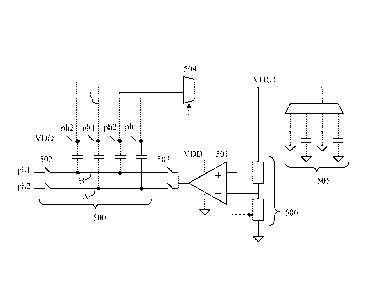
[0054] Figure 5 shows a representative circuit schematic of the present
invention. A
Dickson charge pump 500 is combined with a single low voltage amplifier 501;
the operation of
the amplifier 501 is interleaved with the operation of the charge pump 500
through switches 502
503. When operating as a charge pump (switches 502 closed), the clock signals
(A, B) are driven
with alternating bi-level signals (e.g. the two levels 0 and VDD). During
amplification mode when
switches 503 are closed and switches 502 are open, one of the clock signals (A
or B) is driven by
the output of the low voltage amplifier 501 while the output multiplexor 504
connects one of the
Dickson charge pump 500 nodes to the selected voltage output stabilizing
capacitor 505. The
feedback network 506 is switched as well and allows the low voltage amplifier
506 to stabilize
9
CA 02771935 2012-02-23
WO 2011/023672 PCT/EP2010/062289
stabilize VOUT at the desired high voltage. Each regulated output voltage has
a pin with a
stabilizing capacitor 505 which allows the sequential update of a number of
output voltages.
[0055] Figure 6 shows a representative example timing waveform diagram of the
circuit of
Figure 5 refreshing a single output VOUT in between charge pump cycles. The
charge pump
clock signals A, B are first clocked with bi-level drive signals during the
charge pump phase;
switches controlled by phl and ph2 in Figure 5 are open and closed at this
time. Then during the
regulation phase, one of the switches 503 is closed, in this example the lower
one, so that the node
A is driven by the amplifier. The node C voltage is thus the sum of the pump
capacitor between
nodes A,C (which will have -2*VDD across it) and the output of the low voltage
amplifier 501.
This selected capacitor node C is connected to the output voltage VOUT using
mux 504 during
the regulation phase. In addition, the VOUT node is connected to the feedback
network 506
during the regulation phase to close the regulation loop. Once the amplifier
501 has settled, the
charge pump can go back to the charge pump mode to replenish the pump
capacitors' 500 charge
state.
[0056] Those skilled in the art will recognize the large number of
interleaving
permutations available to the designer - the charge pumping clock phase might
consist of as little
as a brief level where phl or ph2 switches are activated. Alternatively, a
number of complete phl
and ph2 cycles may be completed before entering a regulation phase. Multiple
outputs may be
regulated sequentially before returning to charge pumping as well. Such
permutations,
combinations, groupings can address various engineering objectives (e.g.
improve the impedance
of one or more outputs, reduce clock transition count, etc.); such design
choices of interleaving
particular charge pump phases and regulation outputs are considered within the
scope of the
present invention.
[0057] The key advantage of the present teachings over the combinations of a
multi-rail
charge pump and conventional class G power rail multiplexors and high voltage
amplifier shown in
Figures 3 and 4 is that the amplifier of the present teachings can be
constructed with low voltage
transistors which generally are much lower power, faster and smaller area than
the high voltage
transistors available in common mixed voltage CMOS IC processes. The increased
settling
CA 02771935 2012-02-23
WO 2011/023672 PCT/EP2010/062289
settling performance of the low voltage amplifier (vs. a high voltage one)
means that the amplifier
can rapidly stabilize an output; this in turn opens the possibility to time-
multiplex the high voltage
output onto multiple stabilizing capacitors, creating many voltages from a
single amplifier. Also,
since the amplifier is faster, it can be shut down in between output refresh
cycles at very light
loads, thereby conserving even more power. Furthermore, the quiescent power
dissipation of the
low voltage amplifier is substantially less than the equivalent performance
high voltage amplifier
needed for the conventional class G amplifier. Lastly, since the low voltage
amplifier's rails can be
kept stable, the biasing and bias transients associated with switching
amplifier rails as in a
conventional class G amplifier are eliminated. All of these factors decrease
the power and
difficulty of integrating an amplifier to close the loop around a high
impedance (but very low
power) charge pump; the present teachings enable the closed loop payback to be
realized by
minimizing the impact of the amplifier on total power.
[0058] Those skilled in the art will recognize that the Dickson charge pump
can be
replaced by any multiplying or fractional charge pump with available flying
capacitors. A series of
doubling circuits, for example, could easily be provided that employ the ideas
presented herein to
drive one side of a series of one or more pump/flying capacitors with a low
voltage amplifier
output while closing the feedback loop around the high output voltage of the
amplifier plus one or
more series pump capacitors. By keeping the voltage range of the amplifier
low, faster and lower
power components can be used for the linear amplification and bias current
power dissipation can
be kept at a minimum. The specific topology of charge pump is not considered a
limitation of the
present teachings.
11