Note : Les descriptions sont présentées dans la langue officielle dans laquelle elles ont été soumises.
CA 02773156 2012-03-05
WO 2011/026527 PCT/EP2009/061551
AN APPARATUS
The present application relates to a method and apparatus. In some
embodiments the method and apparatus relate to image processing and in
particular, but not exclusively limited to, some further embodiments relate to
multi-frame image processing.
Imaging capture devices and cameras are generally known and have been
implemented on many electrical devices. Multi-frame imaging is a technique
which may be employed by cameras and image capturing devices. Such
multi-frame imaging applications are, for example, high or wide dynamic range
imaging in which several images of the same scene are captured with
different exposure times and then can be combined to a single image with
better visual quality. The use of high dynamic range/wide dynamic range
applications allows the camera to then filter the intense back light
surrounding
and on the subject and enhance the ability to distinguish features and shapes
on the subject. Thus, for example where light enters a room from various
angles, a camera placed on the inside of a room will be able to see through
the intense sunlight or artificial light entering the room and see the subject
within the room. Traditional single frame images do not provide an acceptable
level of performance as they will either produce an image which is too dark to
show the subject or the background is washed out by the light entering the
room.
Another multi-frame application is multi-frame extended depth of focus or
field
applications where several images of the same scene are captured with
different focus settings. In these applications, the multiple frames can be
combined to obtain an output image which is sharp everywhere.
A further multi-frame application is multi-zoom multi-frame applications where
several images of the same scene are captured with differing levels of optical
zoom. In these applications the multiple frames may be combined to permit
the viewer to zoom into an image without suffering from a lack of detail
1
CA 02773156 2012-03-05
WO 2011/026527 PCT/EP2009/061551
produced in single frame digital zoom operations.
Much effort has been put into attempting to find efficient methods for
combining the multiple images into a single output image. However, current
approaches preclude later processing which may produce better quality
outputs.
The storing of multiple images in original raw data formats although allowing
later processing/viewing is problematic in terms of the amount of memory
required to store all of the images. Furthermore it is of course possible to
encode independently all of the captured images as separate encoded files
and thus reduce the `size' of each image and save all of the files. One such
encoding system known is the joint photographic experts group JPEG
encoding format. Figure 1 shows a structure of a compressed file JPEG
format where the structure table 1 shows a file structure element called
`compressed data' 4 which contains compressed image data according to the
compression algorithm and parameters used. The file structure also shows an
application marker segment 1 which within it contains a first image file
directory (IFD) data field 3 which may contains an optional thumbnail image
corresponding to the compressed full resolution image data.
By encoding separately and storing separately each image from the multi-
frame image even when using compression like JPEG the use of memory is
typically inefficient and furthermore the storing of multiple images of the
same
scene may be determined to be an error by the user as at first viewing these
multiple images will appear to be similar to the user and may lead the user to
delete some of these images by mistake.
This application therefore proceeds from the consideration that an improved
multi-frame imaging processing structure or apparatus may be configured to
more efficiently code and store the multi-frame images yet may also allow
existing decoders to at least partially decode imaging files encoded using the
apparatus.
2
CA 02773156 2012-03-05
WO 2011/026527 PCT/EP2009/061551
According to a first aspect of the invention there is provided a method
comprising capturing a first image of a subject with a first image capture
parameter and at least one further image of substantially the same subject
with at least one corresponding further image capture parameter; encoding
the first image into a first encoded image; encoding the at least one further
image into at least one further encoded image; and combining the first
encoded image and the at least one further encoded image into a first file.
Encoding the at least one of the further image may comprise: decoding the
first encoded image into a first decoded image; determining the differences
between at least part of one of the at least one further image and at least
part
of the first decoded image; and encoding the differences between at least part
of one of the at least one further image and at least part of the first
decoded
image.
Combining the first encoded image and the at least one further encoded
image into a first file may comprise: configuring the first file be decodable
according to a first algorithm and a second algorithm; the first encoded image
being decodable into a first decoded image representing the first image
according to the first algorithm and the second algorithm; and the at least
one
further encoded image being decodable into at least one further decoded
image representing the at least one further image only according to the
second algorithm.
Combining the first encoded image and the at least one further encoded
image into a first file may comprise: logically linking the first encoded
image
and the at least one further encoded image in the first file.
Capturing the first image and the at least one further image is preferably in
response to a user action.
3
CA 02773156 2012-03-05
WO 2011/026527 PCT/EP2009/061551
Capturing the first image and the at least one further image may comprise
capturing the first image and the at least one further image within a period,
the
period being perceived as a single event.
The first encoded image and the at least one further encoded image are
preferably configured to share a same coded data structure.
The method may further comprise determining the number of at least one
further images to be captured.
The method may further comprise selecting an image capture parameter
value for each image to be captured.
Each image capture parameter may comprise at least one of: exposure time;
focus setting; zoom factor; background flash mode; analog gain; and
exposure value.
The method may further comprise inserting a first indicator in the first file
indicating at least one of the first image capture parameter and the at least
one further image capture parameter type.
The method may further comprise inserting at least one indicator in the first
file indicating a value of at least one of the first image capture parameter
and
a value of the at least one of the at least one further image capture
parameter.
Capturing a first image and the at least one further image may comprise at
least one of: capturing the first image and subsequently capturing each of the
at least one further image; and capturing the first image substantially at the
same time as capturing each of the at least one further image.
According to a second aspect of the invention there is provided a method
comprising decoding a first file comprising a first encoded image and at least
one further encoded image, the first image having been captured of a subject
with a first image capture parameter and the at least one further image having
4
CA 02773156 2012-03-05
WO 2011/026527 PCT/EP2009/061551
been captured of substantially the same subject with at least one further
image capture parameter, wherein decoding the first file comprises:
determining at least one of the first encoded image and the at least one
further encoded image to be decoded; decoding the at least one of the first
encoded image and the at least one further encoded image.
The method may further comprise: decoding the first encoded image by a first
decoding algorithm to form a first decoded image; decoding the at least one
further encoded image to generate at least one further image prediction data;
and generating at least one further decoded image by combining the first
decoded image and the at least one further image prediction data.
The first file preferably comprises: at least one first indicator indicating
at least
one of the first image capture parameter type and the at least one further
image capture parameter type, and at least one second indicator indicating at
least one of a first image capture parameter value and at least one further
image capture parameter value; wherein the determining at least one of the
first encoded image and the at least one further encoded image to be
decoded comprises interpreting at least one of the first indicator the at
least
one second indicator.
The method may further comprise determining a number of decoded images
from the first encoded file to be decoded, wherein the number of decoded
images to be decoded is selected by a user.
All encoded images from the first encoded file are preferably decoded.
The method may further comprise selecting the encoded images from the first
encoded file which are to be decoded, wherein the encoded images to be
decoded are selected by the user.
According to a third aspect of the invention there is provided an apparatus
comprising a camera module configured to capture a first image of a subject
with a first image capture parameter and at least one further image of
5
CA 02773156 2012-03-05
WO 2011/026527 PCT/EP2009/061551
substantially the same subject with at least one associated further image
capture parameter; a reference image encoder configured to encode the first
image into a first encoded image; a further image encoder configured to
encode the at least one further image into at least one further encoded image;
and a file compiler configured to combine the first encoding image and the at
least one further encoded image into a first file.
The further image encoder may comprise: an image decoder configured to
decode the first encoded image into a first decoded image; a comparator
configured to determine the differences between at least part of one of the at
least one further image and at least part of the first decoded image; and a
prediction encoder configured to encode the differences between at least part
of one of the at least one further image and at least part of the first
decoded
image.
The file compiler may comprise an image linker configured to logically link
the
first encoded image and the at least one further encoded image in the first
file.
The apparatus may further comprise an image capture interface for enabling
the camera module.
The camera module is preferably further configured to capture the first image
and the at least one further image within a period, the period being perceived
as a single event.
The reference image encoder and the further image encoder are preferably
configured to output the first encoded image and the at least one further
encoded image with a same coded data structure.
The apparatus may further comprise a multi image frame determiner
configured to determine the number of at least one further image to be
captured.
6
CA 02773156 2012-03-05
WO 2011/026527 PCT/EP2009/061551
The apparatus may further comprise a image capture parameter selector
configured to select an image capture parameter value for each image to be
captured.
Each image capture parameter may comprise at least one of: exposure time;
focus setting; zoom factor; background flash mode; analog gain; and
exposure value.
The apparatus may further comprise a parameter type indicator inserter
configured to insert a first indicator in the first file indicating at least
one of the
first image capture parameter and the at least one further image capture
parameter type.
The apparatus may further comprise an parameter value indicator inserter
configured to insert at least one parameter value indicator in the first file
indicating a value of at least one of the first image capture parameter and a
value of the at least one of the at least one further image capture parameter.
The camera module is preferably configured to at least: capture the first
image
and subsequently one or more further images; and capture the first image
substantially at the same time as capturing each of the further images.
According to a fourth aspect of the invention there is provided an apparatus
configured to decode a first file comprising a first encoded image having been
captured of a subject with a first image capture parameter and at least one
further encoded image having been captured of substantially the same subject
with at least one further image capture parameter, the apparatus comprising:
a processor configured to determine at least one of the first encoded image
and the at least one further encoded image to be decoded; and a decoder
configured to decode the at least one of the first encoded image and the at
least one further encoded image.
The decoder preferably comprises: a first decoder configured to decode the
first encoded image by a first decoding algorithm to form a first decoded
7
CA 02773156 2012-03-05
WO 2011/026527 PCT/EP2009/061551
image; at least one further decoder configured to decode the at least one
further encoded image to generate at least one image prediction data; and an
image generator configured to generate at least one further decoded image
by combining the first decoded image and the at least one image prediction
data.
The first file may comprise: at least one first indicator indicating at least
one of
the first image capture parameter type and the at least one further image
capture parameter type, and at least one second indicator indicating at least
one of a first image capture parameter value and at least one further image
capture parameter value; wherein the processor is configured to determine
the at least one of the first encoded image and the at least one further
encoded image to be decoded dependent on interpreting at least one of the
first indicator the at least one second indicator.
The processor is preferably further configured to determine a number of
decoded images from the first encoded file to be decoded, wherein the
number of decoded images to be decoded is selected by a user.
All encoded images from the first encoded file are preferably decoded.
The processor is preferably further configured to select the encoded images
from the first encoded file which are to be decoded, wherein the encoded
images to be decoded are selected by the user.
Each of the at least one further decoder are preferably configured to decode
an associated one of the at least one further encoded images to generate one
or more image prediction data.
An electronic device may comprise apparatus as described above.
A chipset may comprise apparatus as described above.
8
CA 02773156 2012-03-05
WO 2011/026527 PCT/EP2009/061551
A computer readable medium comprising a computer program thereon, the
computer program may perform the method as described above.
According to a fifth aspect of the invention there is provided an apparatus
comprising image capture means for capturing a first image of a subject with a
first image capture parameter and one or more further images of substantially
the same subject each with a corresponding image capture parameter;
encoding means for encoding the first image into a first encoded image;
second encoding means for encoding each of the further images into
corresponding encoded images; and processing means for combining the first
encoding image and at least one of the further encoded images into a first
file.
According to a sixth aspect of the invention there is provided an apparatus
comprising: receiving means for receiving a first file comprising a first
encoded
image and one or more further encoded images, wherein decoding the first file
comprises: first decoding means for decoding the first encoded image by a
first decoding algorithm to form a first decoded image; further decoding means
for decoding at least one of the further encoded image to generate the
corresponding image prediction data; and image generating means for
generating one or more decoded images by combining the first decoded
image and at least one of the corresponding image prediction data.
According to a seventh aspect of the invention there is provided an apparatus
comprising at least one processor and at least one memory including
computer program code the at least one memory and the computer program
code configured to, with the at least one processor, cause the apparatus at
least to perform: capturing a first image of a subject with a first image
capture
parameter and at least one further image of substantially the same subject
with at least one corresponding further image capture parameter; encoding
the first image into a first encoded image; encoding the at least one further
image into at least one further encoded image; and combining the first
encoded image and the at least one further encoded image into a first file.
9
CA 02773156 2012-03-05
WO 2011/026527 PCT/EP2009/061551
According to an eighth aspect of the invention there is provided an apparatus
comprising at least one processor and at least one memory including
computer program code the at least one memory and the computer program
code configured to, with the at least one processor, cause the apparatus at
least to perform: decoding a first file comprising a first encoded image and
at
least one further encoded image, the first image having been captured of a
subject with a first image capture parameter and the at least one further
image
having been captured of substantially the same subject with at least one
further image capture parameter, wherein decoding the first file comprises:
determining at least one of the first encoded image and the at least one
further encoded image to be decoded; decoding the at least one of the first
encoded image and the at least one further encoded image.
For a better understanding of the present application and as to how the same
may be carried into effect, reference will now be made by way of example to
the accompanying drawings in which:
Figure 1 shows schematically the structure of a compressed image file
according to a JPEG file format;
Figure 2 shows a schematic representation of an apparatus suitable for
implementing some embodiments of the application;
Figure 3 shows a schematic representation of apparatus according to
embodiments of the application;
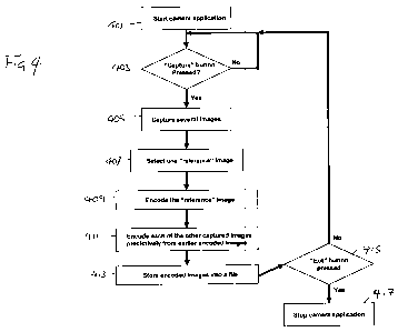
Figure 4 shows a flow diagram of the processes carried out according to some
embodiments.
Figure 5 shows a schematic representation of apparatus according to
embodiments of the application;
Figure 6 shows a flow diagram of the process carried out according to some
embodiments; and
Figure 7 shows schematically the structure of a compressed image file
according to some embodiments of the application.
The application describes apparatus and methods to capture several static
images of the same scene and encode them efficiently into one file. The
CA 02773156 2012-03-05
WO 2011/026527 PCT/EP2009/061551
embodiments described hereafter may be utilised in various applications and
situations where several images of the same scene are captured and stored.
For example, such applications and situations may include capturing two
subsequent images, one with flash light and another without, taking several
subsequent images with different exposure times, taking several subsequent
images with different focuses, taking several subsequent images with different
zoom factors, taking several subsequent images with different analogue
gains, taking subsequent images with different exposure values. The
embodiments as described hereafter store the images in a file in such a
manner that existing image viewers may display the reference image and omit
the additional images. Thus the main embodiment of the application is the
concept of storing multiple images as described within a camera application
framework.
The following describes apparatus and methods for the provision of improved
multi-frame imaging techniques. In this regard reference is first made to
Figure 2 which discloses a schematic block diagram of an exemplary
electronic device 10 or apparatus. The electronic device is configured to
perform multi-frame imaging techniques according to some embodiments of
the application.
The electronic device 10 is in some embodiments a mobile terminal, mobile
phone or user equipment for operation in a wireless communication system.
In other embodiments, the electronic device is a digital camera.
The electronic device 10 comprises an integrated camera module 11, which is
linked to a processor 15. The processor 15 is further linked to a display 12.
The processor 15 is further linked to a transceiver (TX/RX) 13, to a user
interface (UI) 14 and to a memory 16. In some embodiments, the camera
module 11 and / or the display 12 is separate from the electronic device and
the processor receives signals from the camera module 11 via the transceiver
13 or another suitable interface.
11
CA 02773156 2012-03-05
WO 2011/026527 PCT/EP2009/061551
The processor 15 may be configured to execute various program codes 17.
The implemented program codes 17, in some embodiments, comprise image
capture digital processing or configuration code. The implemented program
codes 17 in some embodiments further comprise additional code for further
processing of images. The implemented program codes 17 may in some
embodiments be stored for example in the memory 16 for retrieval by the
processor 15 whenever needed. The memory 15 in some embodiments may
further provide a section 18 for storing data, for example data that has been
processed in accordance with the application.
The camera module 11 comprises a camera 19 having a lens for focusing an
image on to a digital image capture means such as a charged coupled device
(CCD). In other embodiments the digital image capture means may be any
suitable image capturing device such as complementary metal oxide
semiconductor (CMOS) image sensor. The camera module 11 further
comprises a flash lamp 20 for illuminating an object before capturing an image
of the object. The flash lamp 20 is linked to the camera processor 21. The
camera 19 is also linked to a camera processor 21 for processing signals
received from the camera. The camera processor 21 is linked to camera
memory 22 which may store program codes for the camera processor 21 to
execute when capturing an image. The implemented program codes (not
shown) may in some embodiments be stored for example in the camera
memory 22 for retrieval by the camera processor 21 whenever needed. In
some embodiments the camera processor 21 and the camera memory 22 are
implemented within the apparatus 10 processor 15 and memory 16
respectively.
The apparatus 10 may in embodiments be capable of implementing multi-
frame imaging techniques in at least partially in hardware without the need of
software or firmware.
The user interface 14 in some embodiments enables a user to input
commands to the electronic device 10, for example via a keypad, user
operated buttons or switches or by a touch interface on the display 12. One
12
CA 02773156 2012-03-05
WO 2011/026527 PCT/EP2009/061551
such input command may be to start a multiframe image capture process by
for example the pressing of a 'shutter' button on the apparatus. Furthermore
the user may in some embodiments obtain information from the electronic
device 10, for example via the display 12 of the operation of the apparatus
10.
For example the user may be informed by the apparatus that a multiframe
image capture process is in operation by an appropriate indicator on the
display. In some other embodiments the user may be informed of operations
by a sound or audio sample via a speaker (not shown), for example the same
multiframe image capture operation may be indicated to the user by a
simulated sound of a mechanical lens shutter.
The transceiver 13 enables communication with other electronic devices, for
example in some embodiments via a wireless communication network.
It is to be understood again that the structure of the electronic device 10
could
be supplemented and varied in many ways.
A user of the electronic device 10 may use the camera module 11 for
capturing images to be transmitted to some other electronic device or that is
to be stored in the data section 18 of the memory 16. A corresponding
application in some embodiments may be activated to this end by the user via
the user interface 14. This application, which may in some embodiments be
run by the processor 15, causes the processor 15 to execute the code stored
in the memory 16.
The processor 15 may then process the digital image in the same way as
described with reference to Figure 4.
The resulting image may in some embodiments be provided to the transceiver
13 for transmission to another electronic device. Alternatively, the processed
digital image could be stored in the data section 18 of the memory 16, for
instance for a later transmission or for a later presentation on the display
10
by the same electronic device 10.
13
CA 02773156 2012-03-05
WO 2011/026527 PCT/EP2009/061551
The electronic device 10 may in some embodiments also receive digital
images from another electronic device via its transceiver 13. In these
embodiments, the processor 15 executes the processing program code stored
in the memory 16. The processor 15 may then in these embodiments process
the received digital images in the same way as described with reference to
Figure 4. Execution of the processing program code to process the received
digital images could in some embodiments be triggered as well by an
application that has been called by the user via the user interface 14.
It would be appreciated that the schematic structures described in Figure 3
and the method steps in Figure 4 represent only a part of the operation of a
complete system comprising some embodiments of the application as shown
implemented in the electronic device shown in Figure 2.
Figure 3 shows a schematic configuration for a multi-frame digital image
processing apparatus according to at least one embodiment. The multi-frame
digital image processing apparatus may include a camera module 11, digital
image processor 300, a reference image selector 302, a reference image
encoder 304, a residual image encoder 306 and a file compiler 308.
In some embodiments of the application the multi-frame digital image
processing apparatus may comprise some but not all of the above parts. For
example in some embodiments the apparatus may comprise only the digital
image processor 300, reference image selector 302, reference image encoder
304 and residual image encoder 306. In these embodiments the digital image
processor 300 may carry out the action of the file compiler 308 and output a
processed image to the transmitter/storage medium/display.
In other embodiments of the digital image processor 300 may be the "core"
element of the multi-frame digital image processing apparatus and other parts
or modules may be added or removed dependent on the current application.
In other embodiments, the parts or modules represent processors or parts of a
single processor configured to carry out the processes described below, which
are located in the same, or different chip sets. Alternatively the digital
image
14
CA 02773156 2012-03-05
WO 2011/026527 PCT/EP2009/061551
processor 300 is configured to carry out all of the processes and Figure 3
exemplifies the processing and encoding of the multi-frame images.
The operation of the multi-frame digital image processing apparatus parts
according to at least one embodiment will be described in further detail with
reference to Figure 4. In the following example the multi-frame image
application is a wide-exposure image, in other words where the image is
captured with a range of different exposure levels or time. It would be
appreciated that any other of the multi-fame digital images as described
previously may also be carried using similar processes. Where elements
similar to those shown in Figure 2 are described, the same reference numbers
are used.
The camera module 11 may be initialised by the digital image processor 300
in starting a camera application. As has been described previously, the
camera application initialisation may be started by the user inputting
commands to the electronic device 10, for example via a button or switch or
via the user interface 14.
When the camera application is started, the apparatus 10 may start to collect
information about the scene and the ambiance. At this stage, the different
settings of the camera module 11 may be set automatically if the camera is in
the automatic mode of operation. For the example of a wide-exposure multi-
frame digital image the camera module 11 and the digital image processor
300 may determine the exposure times of the captured images based on a
determination of the image subject. Different analog gains or different
exposure values can be automatically detected by the camera module 11 and
the digital image processor 300 in a multiframe mode. Where, the exposure
value is the combination of the exposure time and analog gain.
In wide-focus multi-frame examples the focus setting of the lens may be
similarly determined automatically by the camera module 11 and the digital
image processor 300. In some embodiments the camera module 11 may have
a semi-automatic or manual mode of operation where the user may via the
CA 02773156 2012-03-05
WO 2011/026527 PCT/EP2009/061551
user interface 14 fully or partially choose the camera settings and the range
over which the multi-frame image will operate. Examples of such settings that
could be modified by the user include a manually focusing, zooming, choosing
a flash mode setting for operating the flash 20, selecting an exposure level,
selecting an analog gain, selecting an exposure value, selecting auto white
balance, or any of the settings described above.
Furthermore when the camera application is started, the apparatus 10 for
example the camera module 11 and the digital image processor 300 may
further automatically determine the number of images or frames that will be
captured and the settings used for each images. This determination may in
some embodiments be based on information already gathered on the scene
and the ambiance. In other embodiments this determination may be based on
information from other sensors, such as an imaging sensor, or a positioning
sensor capable of locating the position of the apparatus. Examples of such
positioning sensor are Global positioning system (GPS) location estimators
and cellular communication system location estimators, and accelerometers.
Thus in some embodiments the camera module 11 and the digital image
processor 300 may determine the range of exposure levels, and/or a
exposure level locus (for example a `starting exposure level', a `finish
exposure level' or a `mid-point exposure level') about which the range of
exposure levels may be taken for the multi-frame digital image application. In
some embodiments the camera module 11 and the digital image processor
300 may determine the range of the analog gain and/or the analog gain locus
(for instance a `starting analog gain', a 'finish analog gain' or a `mid-point
analog gain') about which the analog gain may be set for the multi-frame
digital image application. In some embodiments the camera module 11 and
the digital image processor 300 may determine the range of the exposure
value and/or the exposure value locus (for instance a `starting exposure
value', a `finish exposure value' or a `mid-point exposure value') about which
the exposure value may be set for the multi-frame digital image application.
Similarly in some embodiments in wide-focus multi-frame examples the
camera module 11 and the digital image processor 300 may determine the
16
CA 02773156 2012-03-05
WO 2011/026527 PCT/EP2009/061551
range of focus settings, and/or focus setting locus (for example a `starting
focus setting, a `finish focus setting' or a `mid-point focus setting') about
which
the focus setting may be set for the multi-frame digital image application.
In some embodiments, the user may furthermore modify or choose these
settings and so can define manually the number of images to be captured and
the settings of each of these images or a range defining these images.
The initialisation or starting of the camera application within the camera
module 11 is shown in Figure 4 by the step 401.
The digital image processor 300 in some embodiments may then perform a
polling or waiting operation where the processor waits to receive an
indication
to start capturing images. In some embodiments of the invention, the digital
image processor 300 awaits an indicator signal which may be received from a
"capture" button. The capture button may be a physical button or switch
mounted on the apparatus 10 or may be part of the user interface 14
described previously.
While the digital image processor 300 awaits the indicator signal, the
operation stays at the polling step. When the digital image processor 300
receives the indicator signal (following the pressing of the capture button),
the
digital image processor may communicate to the camera module 11 to start to
capture several images dependent on the settings of the camera module as
determined in the starting of the camera application operation. The processor
in some embodiments may perform an additional delaying of the image
capture operation where in some embodiments a timer function is chosen and
the processor may communicate to the camera module to start capturing
images at the end of timer period.
The polling step of waiting for the capture button to be pressed is shown in
Figure 4 by step 403.
17
CA 02773156 2012-03-05
WO 2011/026527 PCT/EP2009/061551
On receiving the signal to begin capturing images from the digital image
processor 300, the camera module 11 then captures several images as
determined by the previous setting values. In embodiments employing wide-
exposure multi-frame image processing the camera module may take several
subsequent images of the same or substantially same viewpoint, each frame
having a different exposure time or level determined by the exposure time or
level settings. For example the settings may determine that 5 images are to
be taken with linearly spaced exposure times starting from a first exposure
time and ending with a fifth exposure time. It would be appreciated that
embodiments may have any suitable number of images or frames in a group
of images. Furthermore it would be appreciated that the captured image
differences may not be linear, for example there may be a logarithmic or other
non-linear difference between images.
In a further example, where the camera-flash is the determining factor
between image capture frames the camera module 11 may capture two
subsequent images, one with flashlight and another without. In a further
example the camera module 11 may capture any suitable number of images,
each one employing a different flashlight parameter - such as flashlight
amplitude, colour, colour temperature, length of flash, inter pulse period
between flashes.
In other embodiments where the focus setting is the determining factor
between image capture frames the camera module 11 may take several
subsequent images with different focus setting. In further embodiments where
the zoom factor is the determining factor the camera module 11 may take
several subsequent images with different zoom factors (or focal lengths). In
further embodiments the camera module 11 may take several subsequent
images with different analog gains or different exposure values. Furthermore
in some embodiments the subsequent images captured may differ using one
or more of the above factors.
In some embodiments the camera module 11, rather than taking subsequent
images, in other words serially capturing images one after another may
18
CA 02773156 2012-03-05
WO 2011/026527 PCT/EP2009/061551
capture multiple images substantially at the same time using a first image
capture arrangement to capture a first image with a first setting exposure
time,
and a second capture arrangement to capture substantially the same image
with a different exposure time. In some embodiments, more than two capture
arrangements may be used with an image with a different exposure time
being captured by each capture arrangement. Each capture arrangement may
be a separate camera module 11 or may in some embodiments be a separate
sensor in the same camera module 11.
In other embodiments the different capture arrangements may use the same
physical camera module 11 but may be generated from processing the output
from the capture device. In these embodiments the optical sensor such as the
CCD or CMOS may be sampled and the results processed to build up a series
of `image frames'. For example the sampled outputs from the sensors may be
combined to produce a range of values faster than would be possible by
taking sequential images with the different determining factors. For example
in
wide-exposure multi-frame processing three different exposure frames may be
captured by taking a first image sample output after a first period to obtain
a
first image after a first exposure time, a second image sample output a
second period after the first period to obtain a second image with a second
exposure time and adding the first image sample output to the second image
sample output to generate a third image sample output with a third exposure
time approximately equal to the first and second exposure time combined.
The camera module 11 may then pass the captured image data to the digital
image processor 300 for all of the captured image frame data.
The operation of capturing multi-frame images is shown in Figure 4 by step
405.
The digital image processor 300 then may pass the captured image data to
the reference image selector 302 where the reference image selector 302 is
configured to select a reference image from the plurality of images captured.
19
CA 02773156 2012-03-05
WO 2011/026527 PCT/EP2009/061551
In some embodiments, the reference image selector 302 determines an
estimate of the image visual quality of each image and the image with the best
visual quality is selected as the reference. In some embodiments, the
reference image selector may determine the image visual quality to be based
on the image having a central part in focus. In other embodiments, the
reference image selector 302 selects the reference image as the image
according to any suitable metrics or parameter associated with the image. In
some embodiments the reference image selector 302 selects one of the
images dependent on receiving a user input via the user interface 14. In other
embodiments the reference image selector 302 performs a first filtering of the
images based on some metric or parameter of the images and then the user
selects one of the remaining images as the reference image.
These manual or semi-automatic reference image selections in some
embodiments are carried out where the digital image processor 300 displays a
range of the captured images to the user via the display 12 and the user
selects one of the images by any suitable selection means. Examples of
selection means may be in the form of the user interface 14 in terms of a
touch screen, keypad, button or switch.
The reference image selection is shown in Figure 4 by step 407.
The digital image processor 300 then sends the selected reference image to
the reference image encoder 304 where the reference image encoder may
perform any suitable encoding algorithm on the reference image to generate
an encoded reference image. In some embodiments the reference image
encoder performs a standard JPEG encoding on the referenced image with
the JPEG encoding parameters determined either automatically, semi-
automatically or manually by the user. The encoded reference image may in
some embodiments be passed back to the digital image processor 300.
The encoding of the reference image is shown in Figure 4 by step 409.
CA 02773156 2012-03-05
WO 2011/026527 PCT/EP2009/061551
The digital image processor 300 in some embodiments sends the non-
reference images to the residual image encoder 306 which then encodes the
non-reference images. In some embodiments the digital image processor 300
may also send a copy of the reference image to the residual image encoder
306 so that the residual image encoder 306 may encode the remaining
images predictively using the referenced image as a prediction reference
image.
Thus in some embodiments the differences, pixel by pixel, between the
reference image and each of the other captured images are computed by the
residual image encoder 306. For example in colour images, the difference
may in some embodiments be computed for each colour component. In some
embodiments the residual image encoder 306 may then perform a spatial to
frequency domain transform. As the captured images are of the same scene,
the images will be similar and therefore the computed and transformed
images will likely only contain a few high frequency (details) differences and
encoding of these differences will be very efficient. In these embodiments the
residual image encoder 306 may encode the differences using a JPEG
encoding technique.
In some embodiments where non-reference images are not similar to the
reference image, for example where the images are captured with different
exposure times or with different analogue gain, the residual image encoder
306 may precode these non-similar images to become more similar to the
referenced image. For example the residual image encoder 306 may apply an
inverse of the camera response function to transform all captured images in
the radiance map domain. In other embodiments, the residual image encoder
306 may apply any suitable transformation as part of a precoding to render
the other image frames similar to the reference frame. The residual image
encoder 306 may store the type and parameter values of the precoding
process into the file. The stored type and parameter values may enable a
decoder to perform an inverse precoding process and hence reconstruct a
decoded image similar to the captured image before the original image
precoding and coding.
21
CA 02773156 2012-03-05
WO 2011/026527 PCT/EP2009/061551
In some embodiments the residual image encoder may apply motion
compensation transformation coding to the other non-reference images. This
motion compensated transform coding may use the reference image as a
single reference image source. Alternatively or in addition, the motion
compensated transform coding may select one of previously encoded images
as a reference image source for a particular part of the image being encoded,
while the motion compensated transform coding may select another
previously encoded image as a reference image source for another part of the
image being encoded. Alternatively or in addition, the motion compensated
transform coding may use more than one previously encoded image as a
motion compensation transformation reference frame (a secondary reference
image) for a particular part of the image being encoded. Typically, a pixel-
wise average of two reference image sources may be performed to form a bi-
prediction motion compensation encoding system. Alternatively in some
embodiments, a pixel-wise weighted average may be used in bi-predictive
motion compensation encoding, where the weights may be implicitly derived
from capturing parameters or explicitly selected, for example, to form a good
prediction signal for the image being encoded. When the weights are
explicitly selected, the weights may be also indicated in the same file where
the images are stored.
The type of motion compensation transformation applied by the residual
image encoder may vary on an image or image segment basis. The type of
motion compensation transformation may not in some embodiments be limited
to translational motion but any higher degree of a motion model may be used.
The residual image encoder may generate an indication of the type of motion
compensation transformation in the file for all non-reference images in the
file,
for each non-reference image separately, for a group of image segments
sharing the same type of motion compensation transformation or for each
image segment. The residual image encoder may also in some embodiments
store other parameter values of the motion compensation transformation,
such as motion vectors, into the file.
22
CA 02773156 2012-03-05
WO 2011/026527 PCT/EP2009/061551
In other embodiments the residual image encoder 306 may first precode at
least one of the non-reference images to become more similar to the
reference image as described above and then use the precoded non-
reference image as a secondary reference images for bi-prediction or inter-
prediction encoding.
In further embodiments the residual image encoder 306 may apply both
motion compensation and difference encoding to parts of the image being
encoded.
In further embodiments the residual image encoder 306 may resample the
prediction reference images before applying predictive coding such as
described previously. This re-sampling of the reference image may be
particularly useful in embodiments where the different images and frames
have different zoom factors. An example of a reference picture re-sampling
process is provided by Annex P of ITU-T recommendation H.263.
The residual image encoder 306 then outputs the encoded residual image to
the digital image processor 300.
The encoding of the other captured images predictively from other earlier
encoded images is shown in Figure 4 by step 411.
The digital image processor 300 may then pass the encoded image files to the
file compiler 308. The file compiler 308 on receiving the encoded reference
image and the encoded non-reference image data compiles the data into a
single file so that an existing file viewer can still decode and render the
referenced image.
Thus in some embodiments the file compiler 308 may compile the file so that
the reference image is encoded as a standard JPEG picture and the
predictively encoded non-reference images are added as exchangeable
image file format (EXIF) data or extra data in the same file.
23
CA 02773156 2012-03-05
WO 2011/026527 PCT/EP2009/061551
The file compiler may in some embodiments compile a file where the
predictively encoded non-reference images are located as a second or further
image file directory (IFD) field of the EXIF information part of the file
which as
shown in figure 1 may be part of a first application data field (APP1) of the
JPEG file structure. In other embodiments the file compiler 308 may compile
a single file so that the encoded non-reference images are stored in the file
as
an additional application segment, for example an application segment with a
designation APP3. In other embodiments the file compiler 308 may compile a
multi-picture (MP) file formatted according to the CIPA DC-007-2009 standard
by the Camera & Image Products Association (CIPA). A MP file comprises
multiple images (First individual image) 651, (Individual image #2) 653,
(individual image #3) 655, (individual image #4) 657, each formatted
according to JPEG and EXIF standards, and concatenated into the same file.
The application data field APP2 601 of the first image 651 in the file
contains a
multi-picture index field (MP Index IFD) 603 that can be used for accessing
the other images in the same file as indicated in Figure 7. The file compiler
308 may in some embodiments set the Representative Image Flag in the
multi-picture index field to 1 for the reference image and to 0 for the non-
reference images. The file compiler 308 furthermore may in some
embodiments set the MP Type Code value to indicate a Multi-Frame Image
and the respective sub-type to indicate the camera setting characterizing the
difference of the images stored in the same file, i.e. the sub-type may be one
of exposure time, focus setting, zoom factor, flashlight mode, analog gain,
and
exposure value.
The file compiler 308 may in some embodiments compile two files. A first file
may be formatted according to JPEG and EXIF standards and comprise one
of the plurality of images captured, which may be the reference image or the
image with the estimated best visual quality. The first file can be decoded
with legacy JPEG and EXIF compatible decoders. A second file may be
formatted according to an extension of JPEG and/or EXIF standards and
comprise the plurality of images captured. The second file may be formatted
in a way to enable the file to be not decoded with a legacy JPEG and EXIF
compatible decoders. In other embodiments, the file compiler 308 may
24
CA 02773156 2012-03-05
WO 2011/026527 PCT/EP2009/061551
compile a file for each of the plurality of images captured. The files may be
formatted according to JPEG and EXIF standards.
In those embodiments where the file complier 308 compiles at least two files
from the plurality of images captured, it may further link the files logically
and/or encapsulate them into the same container file. In some embodiments
the file compiler 308 may name the at least two files in such a manner that
the
file names differ only by extension and one file has jpg extension and is
therefore capable of being processed by legacy JPEG and EXIF compatible
decoders. The files therefore may form a DCF object according to "Design
rule for Camera File system" specification by Japan Electronics and
Information Technology Industries Association (JEITA).
In various embodiments the file compiler 308 may generate or dedicate a new
value of the compression tag for the non-reference predictively coded images.
The compression tag is one of the header fields included in the Application
Marker Segment 1 (APP1) of JPEG files. The compression tag typically
indicates the decompression algorithm that should be used to reconstruct a
decoded image from the compressed image stored in the file. The
compression tag of the reference image may in some embodiments be set to
indicate a JPEG compression/decompression algorithm. However, as JPEG
decoding may not be sufficient for correct reconstruction of the non-reference
image or images, a distinct or separate value of the compression tag may be
used for the non-reference images.
In these embodiments a standard JPEG decoder may then detect or `see' only
one image, the reference image, which has been encoded according to
conventional JPEG standards. Any decoders supporting these embodiments
will 'see' and be able to decode the non-reference images as well as the
reference image.
In some other embodiments the file compiler 308 may receive the reference
image data and difference data from the non-reference images and
concatenate the reference image data with the computed difference data to
CA 02773156 2012-03-05
WO 2011/026527 PCT/EP2009/061551
form a larger image. The resulting image may then be passed to the
reference image encoder 304 and JPEG encoded. In such embodiments the
reference image is present in the top left corner of the JPEG encoded image
and may be indicated by the pixel x dimension and the pixel y dimension EXIF
tags inserted into the image file format. In these embodiments a conventional
JPEG decoder may decode the full JPEG encoded image but crop the image
as one indicated by pixel x dimension and pixel y dimension EXIF tag. In
other words a conventional JPEG decoder will output the referenced image.
However in other decoders the JPEG encoded image may be first decoded
conventionally and then the decoded image may be split into a decoded
reference image (and or images) and the remaining difference images. The
original non-reference images may be obtained by summing the decoded
reference image and the decoded difference image data separately.
The compiling of reference and non-reference images into a single file
operation is shown in Figure 4 by step 413.
The digital image processor 300 may then determine whether or not the
camera application is to be exited, for example, by detecting a pressing of an
exit button on the user interface for the camera application. If the processor
300 detects that the exit button has been pressed then the processor stops
the camera application, however if the exit button has not been detected as
being pressed, the processor passes back to the operation of polling for a
image capture signal.
The polling for an exit camera application indication is shown in Figure 4 by
step 415.
The stopping of the camera application is shown in Figure 4 by operation 417.
An apparatus for decoding a file according to our invention is schematically
depicted in Figure 5. The apparatus comprises a processor 451, a reference
image decoder 453 and a residual image decoder 455. In some embodiments,
26
CA 02773156 2012-03-05
WO 2011/026527 PCT/EP2009/061551
the parts or modules represent processors or parts of a single processor
configured to carry out the processes described below, which are located in
the same, or different chip sets. Alternatively the processor 451 is
configured
to carry out all of the processes and Figure 5 exemplifies the processing and
decoding of the multi-frame images.
The processor 451 may receive the encoded file from a receiver or recording
medium. In some embodiments the encoded file can be received from another
device while in other embodiments the encoded file can be received by the
processor 451 from the same apparatus or device, for instance when the
encoded file is stored in the device that contains the processor. In some
embodiments, the processor 451 passes the encoded file to the reference
image decoder 453. The reference image decoder 453 decodes the reference
image from the encoded file. In some other embodiments of the invention the
processor 451 sends the encoded file to the residual image decoder 453
which extracts and decodes at least one residual image from the encoded file.
In some other embodiments, the decoding of the reference and of the residual
images is carried out at least partially in the processor 451.
The operation of decoding a multi-frame encoded file according to some
embodiments of the application is described schematically with reference to
Figure 6. The decoding process of the multi-frame encoded file may be
started by the processor 451 for example when a user switches to the file in
an image viewer or gallery application. The operation of starting decoding is
shown in Figure 6 by step 501.
The decoding process may be stopped by the processor 451 for example by
pressing an "Exit" button or by exiting the image viewer or gallery
application.
The polling of the "Exit" button to determine if it has been pressed is shown
in
Figure 6 by step 503. If the "Exit" button has been pressed the decoding
operation passes to the stop decoding operation as shown in Figure 6 by step
505.
27
CA 02773156 2012-03-05
WO 2011/026527 PCT/EP2009/061551
According to this figure, when the decoding process is started and if the
"Exit"
button is not pressed (or if the decoding process is not stopped by any other
means) the first operation is to select the decoding mode. The selection of
the
decoding mode according to some embodiments is the selection of decoding
in either single-frame or multi-frame mode. In some embodiments, the mode
selection can be done automatically based on the number of images stored in
the encoded file, i.e., if the file comprises multiple images, a multi-frame
decoding mode is used. In some other embodiments, the capturing
parameters of various images stored in the file may be examined and the
image having capturing parameter values that are estimated to suit user
preferences (adjustable for example through a user interface (UI)),
capabilities
of the viewing device or application, and/or viewing conditions, such as the
amount of ambient light, is selected for decoding. For example, if the file is
indicated to contain two images and also contains an indication that the two
images are intended for displaying on a stereoscopic display device, but the
viewing device only is a conventional monoscopic (two-dimensional) display,
the processor 451 may determine that a single-frame decoding mode is used.
In another example, a file comprises two images differing may have an
indicator which indicates that the images differ in their exposure time. An
image with the longer exposure time, hence a bright picture compared to the
image with the shorter exposure time, may be selected by the processor 451
for viewing when there is a large amount of ambient light detected by the
viewing device. In such an example the processor may, if the image selected
for decoding is the reference image, select the single-frame decoding mode;
otherwise, the processor may select the multi-frame decoding mode is used.
In other embodiments the selection of the mode is done by the user for
instance through a user interface (UI). The selection of the mode of decoding
is shown in Figure 6 by step 507.
If the selected mode is single-frame then only the reference image is decoded
and shown on the display. The determination of whether the decoding is
single or multi-frame is shown in Figure 6 by step 509. The decoding of only
the reference image is shown in Figure 6 by step 511. The showing or
displaying of only the reference image is shown in Figure 6 by step 513.
28
CA 02773156 2012-03-05
WO 2011/026527 PCT/EP2009/061551
If the selected mode is multi-frame, the reference image and at least one
residual image are decoded. The decoding of the reference image as the first
image to be decoded for the multi-frame decoding operation is shown in
Figure 6 by step 515. In some embodiments the number of residual images
that are extracted from the encoded file can be automatically selected by the
residual image decoder 455 while in some other embodiments this number
can be selected by the user through an appropriate UI. In some other
embodiments the residual images to be decoded together with the reference
image can be selected manually by the user through an UI. The selection of
the number and which of the images are to be decoded is shown in Figure 6
by step 517.
In some embodiments, the decoding of a residual image comprises the
operation of identifying the compression type used for generating the residual
image. The operation of identification of the compression type used for the
residual image may comprise interpreting a respective indicator stored in the
file. If the compression type indicator indicates that prediction from other
images is not used in compression, such as in the case of JPEG
compression, decoding the residual image may comprise performing in the
residual image decoder 455 the processing steps for image decoding, such as
rescaling of quantized transform coefficients and an inverse transform from a
transform domain to a pixel domain.
Where the compression type indicator indicates that prediction from other
images is used to generate the file, decoding of the residual image may
comprise performing in the residual image decoder 455 the processing steps
of decoding the difference or prediction error image, decoding a type and
parameters of predictive coding, such as motion vectors, from the file, and
adaptively combining the difference image and the previously decoded image
or images on the basis of the type and parameters of predictive coding. The
steps of the decoding of the residual image may be done on a block by block
basis. Decoding the difference image may comprise performing in the residual
29
CA 02773156 2012-03-05
WO 2011/026527 PCT/EP2009/061551
image decoder 455 the processing steps for image decoding for a single non-
referenced image as described above.
The operation of adaptive combination the difference image and the
previously decoded image may comprise performing in the residual image
decoder 455 the processing steps of determining a prediction block within a
previously decoded image on the basis of a motion vector and summing pixel-
wise the respective colour component values of a prediction block and a
difference block. If the precoding type and parameters are indicated in the
file,
the decoding of a residual image may further comprise performing in the
residual image decoder 455 an inverse process for the precoding. It is noted
that the inverse process for the precoding may also be approximate, i.e. in
the
cascaded process of precoding and inverse precoding the original pixel values
may be approximately but not necessarily exactly reconstructed. The
operation of decoding the images in the multi-frame mode of decoding is
shown in Figure 6 by step 519.
Thus in some embodiments of the application there is a method comprising
the operations of capturing a first image of a subject with a first image
capture
parameter and at least one further image of substantially the same subject
with at least one corresponding further image capture parameter, encoding
the first image into a first encoded image, encoding the at least one further
image into at least one further encoded image, and combining the first
encoded image and the at least one further encoded image into a first file.
In some other embodiments of the application there is a method comprising
the operations of decoding a first file comprising a first encoded image and
at
least one further encoded image, the first image having been captured of a
subject with a first image capture parameter and the at least one further
image
having been captured of substantially the same subject with at least one
further image capture parameter. In such embodiments the operation of
decoding the first file comprises the operations of determining at least one
of
the first encoded image and the at least one further encoded image to be
CA 02773156 2012-03-05
WO 2011/026527 PCT/EP2009/061551
decoded, and decoding the at least one of the first encoded image and the at
least one further encoded image.
Furthermore in some embodiments there may be an apparatus comprising at
least one processor and at least one memory including computer program
code the at least one memory and the computer program code configured to,
with the at least one processor, cause the apparatus at least to perform the
operations described above.
For example in some embodiments there may be an apparatus comprising a
camera module configured to capture a first image of a subject with a first
image capture parameter and at least one further image of substantially the
same subject with at least one associated further image capture parameter, a
reference image encoder configured to encode the first image into a first
encoded image, a further image encoder configured to encode the at least
one further image into at least one further encoded image, and a file compiler
configured to combine the first encoding image and the at least one further
encoded image into a first file.
Also in some embodiments there may be an apparatus configured to decode
a first file comprising a first encoded image having been captured of a
subject
with a first image capture parameter and at least one further encoded image
having been captured of substantially the same subject with at least one
further image capture parameter, the apparatus comprising a processor
configured to determine at least one of the first encoded image and the at
least one further encoded image to be decoded; and a decoder configured to
decode the at least one of the first encoded image and the at least one
further
encoded image.
In some embodiments, after the reference and the selected residual images
have been decoded at least one of them are shown on the display and the
decoding process is restarted for the next encoded file. The operation of
showing or displaying some or all of the decoded images is shown in Figure 6
by step 521.
31
CA 02773156 2012-03-05
WO 2011/026527 PCT/EP2009/061551
In other embodiments, the reference and the selected residual images are not
shown on the display, but may be processed by various means. For example,
the reference and the selected residual images may be combined into one
image, which may be encoded again for example by a JPEG encoder, and it
may be stored in a file located in a storage medium or transmitted to further
apparatus.
It shall be appreciated that the term user equipment is intended to cover any
suitable type of wireless user equipment, such as mobile telephones, portable
data processing devices or portable web browsers. Furthermore user
equipment, universal serial bus (USB) sticks, and modem data cards may
comprise apparatus such as the apparatus described in embodiments above.
In general, the various embodiments of the invention may be implemented in
hardware or special purpose circuits, software, logic or any combination
thereof. For example, some aspects may be implemented in hardware, while
other aspects may be implemented in firmware or software which may be
executed by a controller, microprocessor or other computing device, although
the invention is not limited thereto. While various aspects of the invention
may be illustrated and described as block diagrams, flow charts, or using
some other pictorial representation, it is well understood that these blocks,
apparatus, systems, techniques or methods described herein may be
implemented in, as non-limiting examples, hardware, software, firmware,
special purpose circuits or logic, general purpose hardware or controller or
other computing devices, or some combination thereof.
The embodiments of this invention may be implemented by computer software
executable by a data processor of the mobile device, such as in the processor
entity, or by hardware, or by a combination of software and hardware. Further
in this regard it should be noted that any blocks of the logic flow as in the
Figures may represent program steps, or interconnected logic circuits, blocks
and functions, or a combination of program steps and logic circuits, blocks
and functions. The software may be stored on such physical media as
32
CA 02773156 2012-03-05
WO 2011/026527 PCT/EP2009/061551
memory chips, or memory blocks implemented within the processor, magnetic
media such as hard disk or floppy disks, and optical media such as for
example DVD and the data variants thereof, CD.
The memory may be of any type suitable to the local technical environment
and may be implemented using any suitable data storage technology, such as
semiconductor-based memory devices, magnetic memory devices and
systems, optical memory devices and systems, fixed memory and removable
memory. The data processors may be of any type suitable to the local
technical environment, and may include one or more of general purpose
computers, special purpose computers, microprocessors, digital signal
processors (DSPs), application specific integrated circuits (ASIC), gate level
circuits and processors based on multi-core processor architecture, as
non-limiting examples.
Embodiments of the inventions may be practiced in various components such
as integrated circuit modules. The design of integrated circuits is by and
large
a highly automated process. Complex and powerful software tools are
available for converting a logic level design into a semiconductor circuit
design
ready to be etched and formed on a semiconductor substrate.
Programs, such as those provided by Synopsys, Inc. of Mountain View,
California and Cadence Design, of San Jose, California automatically route
conductors and locate components on a semiconductor chip using well
established rules of design as well as libraries of pre-stored design modules.
Once the design for a semiconductor circuit has been completed, the resultant
design, in a standardized electronic format (e.g., Opus, GDSII, or the like)
may be transmitted to a semiconductor fabrication facility or "fab" for
fabrication.
The foregoing description has provided by way of exemplary and non-limiting
examples a full and informative description of the exemplary embodiment of
this invention. However, various modifications and adaptations may become
apparent to those skilled in the relevant arts in view of the foregoing
33
CA 02773156 2012-03-05
WO 2011/026527 PCT/EP2009/061551
description, when read in conjunction with the accompanying drawings and
the appended claims. However, all such and similar modifications of the
teachings of this invention will still fall within the scope of this invention
as
defined in the appended claims.
As used in this application, the term circuitry may refer to all of the
following:
(a) hardware-only circuit implementations (such as implementations in only
analogue and/or digital circuitry) and (b) to combinations of circuits and
software (and/or firmware), such as and where applicable: (i) to a combination
of processor(s) or (ii) to portions of processor(s)/software (including
digital
signal processor(s)), software, and memory(ies) that work together to cause
an apparatus, such as a mobile phone or server, to perform various functions)
and (c) to circuits, such as a microprocessor(s) or a portion of a
microprocessor(s), that require software or firmware for operation, even if
the
software or firmware is not physically present.
This definition of circuitry applies to all uses of this term in this
application,
including in any claims. As a further example, as used in this application,
the
term circuitry would also cover an implementation of merely a processor (or
multiple processors) or portion of a processor and its (or their) accompanying
software and/or firmware. The term circuitry would also cover, for example
and if applicable to the particular claim element, a baseband integrated
circuit
or applications processor integrated circuit for a mobile phone or a similar
integrated circuit in server, a cellular network device, or other network
device.
The term processor and memory may comprise but are not limited to in this
application: (1) one or more microprocessors, (2) one or more processor(s)
with accompanying digital signal processor(s), (3) one or more processor(s)
without accompanying digital signal processor(s), (3) one or more special-
purpose computer chips, (4) one or more field-programmable gate arrays
(FPGAS), (5) one or more controllers, (6) one or more application-specific
integrated circuits (ASICS), or detector(s), processor(s) (including dual-core
and multiple-core processors), digital signal processor(s), controller(s),
receiver, transmitter, encoder, decoder, memory (and memories), software,
34
CA 02773156 2012-03-05
WO 2011/026527 PCT/EP2009/061551
firmware, RAM, ROM, display, user interface, display circuitry, user interface
circuitry, user interface software, display software, circuit(s), antenna,
antenna
circuitry, and circuitry.