Note : Les descriptions sont présentées dans la langue officielle dans laquelle elles ont été soumises.
CA 02774813 2012-03-21
W02011/032680 PCT/EP2010/005624
SILO HAVING A FILLING DEVICE
The invention relates to a silo comprising a silo
compartment. A filler pipe for feeding in bulk material
is arranged in the silo. The filler pipe comprises a
plurality of valve openings arranged at different
heights.
If a silo is filled such that the bulk material can
fall into the silo compartment through a pipe opening
in the roof of the silo, the falling bulk material flow
induces an air movement in the silo compartment. The
air is drawn downward with the bulk material flow and
rises up again in a region remote from the bulk
material flow. This air movement results in finer
particles being separated from coarser particles in the
bulk material. The finer particles are entrained by the
airflow and are primarily deposited in those areas
where the air rises up again. In the case of a silo,
for example, in which the bulk material flow is fed in
at the center, the finer particles concentrate in the
vicinity of the outer wall. Such segregation of the
bulk material is unwanted.
It is known practice for the silo to be provided with a
filler pipe through which the bulk material is fed into
the silo compartment. The filler pipe is provided in
each instance with a plurality of openings which are
arranged at different heights. The bulk material flow
exits in each instance through the lowermost opening
which is still above the filling level of the bulk
material in the silo compartment. Each of the higher-up
openings is closed off by a valve mechanism. The
falling height between the lowermost opening and the
bulk material in the silo compartment is small, with
the result that no segregation of the bulk material
takes place. Silos of this type are known both in an
embodiment in which a plurality of filler pipes are
arranged in the vicinity of the outer wall
CA 02774813 2012-03-21
W02011/032680 - 2 - PCT/EP2010/005624
(WO 00/51924 Al) and in an embodiment with a central
filler pipe ("An anti-segregation tube to counteract
air current segregation", by Are Dyroy and Gisle G.
Enstad, pages 27 to 30, POSTEC Newsletter No. 16,
December 1997). As silos become larger, the forces
acting on the filler pipes during emptying are
considerable. The filler pipes themselves or the valve
mechanisms may become damaged.
The object on which the invention is based is to
present a silo in which it is possible even for large
quantities of bulk material to be added and withdrawn
without damaging the silo. Taking the initially
mentioned prior art as the starting point, the object
is achieved by the features of the independent claims.
Advantageous embodiments can be found in the subclaims.
According to the invention, the filler pipe is arranged
in a feed chamber which is separated from the silo
compartment by a partition wall. A plurality of outlet
openings arranged at different heights are provided in
the partition wall.
First of all, a few terms will be explained. In a
filler pipe the bulk material moves downward under the
influence of gravity. The filler pipe is oriented
vertically in many cases, but other embodiments are
possible in which the filler pipe is inclined with
respect to the vertical.
A valve opening denotes an opening in the filler pipe
through which the bulk material exits from the filler
pipe only when the bulk material in the filler pipe has
banked up to the height of the relevant valve opening.
A bulk material flow in motion passes by the valve
opening without bulk material exiting. Banked-up bulk
material is no longer capable of moving further
CA 02774813 2012-03-21
W02011/032680 - 3 - PCT/EP2010/005624
downward and instead slides through the valve opening
and out of the filler pipe.
When filling the silo, the bulk material passes at a
given time either only through one valve opening of the
filler pipe or through a plurality of valve openings
which are arranged at approximately equal height. These
active valve openings are situated directly above the
filling level in the feed chamber. Lower-down valve
openings are covered by the bulk material in the feed
chamber. The bulk material does not exit through
higher-up valve openings. The bulk material flow thus
exits from the filler pipe exclusively through the
active valve openings which are arranged only slightly
above the filling level in the feed chamber. Therefore,
the bulk material has only a small falling height in
the feed chamber, whereby no segregation takes place.
The filling level in the feed chamber is dependent on
the filling level in the silo compartment. The bulk
material continues to slide from the feed chamber into
the silo compartment through the outlet openings
situated at the corresponding height until the filling
level in the feed chamber is only slightly higher than
the filling level in the silo compartment. Even as it
passes from the feed chamber into the silo compartment,
the bulk material thus has a small falling height, with
the result that segregation is also avoided here.
Outlet openings are provided in the partition wall
which encloses the feed chamber and separates the
latter from the silo compartment. The outlet openings
can have the form of simple perforations and be free of
moving parts. The partition wall can therefore be
designed in a problem-free manner such that it is
sufficiently stable to withstand the forces which occur
when emptying the silo.
CA 02774813 2012-03-21
W02011/032680 - 4 - PCT/EP2010/005624
In order for even large material flows to be able to be
managed, the feed chamber is preferably provided with a
plurality of filler pipes. The filler pipes can be
arranged close to the partition wall. If the valve
openings of the filler pipes are additionally oriented
in a direction opposed to the partition wall, a uniform
filling of the feed chamber thus becomes possible.
The valve openings can be provided with a valve
mechanism such that the valve openings can adopt an
opened and a closed state. In the opened state, bulk
material can pass through the valve openings while, in
the closed state, no bulk material passes through the
valve openings. In the normal state, that is to say
when no external forces are acting, the valve openings
are preferably closed. This can be achieved for example
by means of a flap which is suspended above the valve
opening and is situated in front of the valve opening
due to gravity. If a bulk material flow moves through
the filler pipe and past the valve opening, a vacuum is
generated which causes the valve to be closed even more
firmly. If appropriate, a spring force which keeps the
valve opening in the closed state may additionally be
provided. At the height of the active valve openings,
the bulk material flow cannot fall further downward.
Instead, the bulk material exerts a laterally directed
force onto the wall of the filler pipe. The valve
opening is preferably designed such that it opens under
the influence of this force, with the result that the
bulk material can slide out of the filler pipe.
In an alternative embodiment, baffle plates which
extend inwardly from the wall of the filler pipe are
mounted above the valve openings. The baffle plates
deflect the bulk material flow such that it is at a
distance from the wall of the filler pipe when it
passes by the valve opening. It is only when the bulk
material has banked up to the height of the valve
CA 02774813 2012-03-21
W02011/032680 - 5 - PCT/EP2010/005624
opening that it passes through the valve opening. This
embodiment has the advantage that it dispenses with any
moving parts.
To ensure that the falling height remains low during
transit from the filler pipe into the feed chamber, the
vertical spacing between the valve openings must be
small. The spacing between the upper end of one valve
opening and the lower end of the immediately higher
valve opening is preferably less than 1 m, more
preferably less than 0.5 m, more preferably still less
than 0.3 m. If the valve openings are not arranged
directly above one another but offset laterally with
respect to one another, a height overlap is also
possible. It is particularly possible with such an
overlap for a plurality of valve openings to be active
at the same time, with the bulk material thus exiting
from the filler pipe through a plurality of active
valve openings at the same time.
Even when the bulk material transits from the feed
chamber into the silo compartment through the outlet
openings, the falling height should be small. The same
accordingly applies to the vertical spacing of the
outlet openings relative to one another and to the
spacing between the lowermost outlet opening and the
bottom of the silo compartment. The lowermost valve
opening is preferably arranged just above the lowermost
outlet opening. It is advantageous for the stability of
the construction if the partition wall and the filler
pipe have a connection to the bottom of the silo. It is
also possible for the filler pipe in particular to be
open at its bottom. The outlet openings are preferably
distributed over the circumference of the feed chamber
such that the silo compartment is filled uniformly. For
example, it is possible at one particular height for
from 10 to 20 outlet openings to be distributed over
the circumference of the feed chamber.
CA 02774813 2012-03-21
W02011/032680 - 6 - PCT/EP2010/005624
The silo should be designed in such a way that a
constant bulk material flow from the filler pipe into
the silo compartment via the feed chamber is achieved
during filling without the bulk material banking up in
one of the components. The filler pipe should therefore
be designed such that the maximum possible bulk
material flow in the filler pipe can exit through the
active valve openings. The maximum bulk material flow
through the active valve openings is preferably at
least 10% greater than the maximum bulk material flow
through the filler pipe. The maximum bulk material flow
from the feed chamber into the silo compartment should
in turn be large enough that it is also not possible
for the bulk material to bank up in the feed chamber.
In the case of the silo according to the invention, the
silo compartment cannot be filled up to a uniform
filling height. Rather, the filling level is highest in
the vicinity of the feed chamber and becomes lower as
the distance from the feed chamber increases. The
inclination in the surface of the bulk material
corresponds to the bulk material angle of the material.
In the case of aluminum oxide for aluminum production,
for which the silo according to the invention is
particularly well suited, the bulk material angle is
approximately 30 . The roof of the silo may be inclined
to correspond to the bulk material angle of the
material that is to be stored. The feed chamber is
preferably arranged at a distance from the outer wall
or arranged in the center of the silo such that the
roof has its greatest height at that point and can
slope downwardly toward the sides.
It is also possible for a plurality of feed chambers to
be provided in the silo compartment. This may be
particularly advantageous when an already existing silo
having a small height but a large areal extent is
CA 02774813 2012-03-21
W02011/032680 - 7 - PCT/EP2010/005624
retrofitted according to the invention. With a single
feed chamber, and as a result of the bulk material
angle, such a silo could only be filled to a small
extent.
The advantages of the silo according to the invention
apply particularly when large quantities of bulk
material are to be stored or when large quantities of
material are to be added or withdrawn within a short
time. The volume of the silo is preferably greater than
10,000 m3, more preferably greater than 20,000 m3, more
preferably still greater than 40,000 m3. The capacity of
the silo for aluminum oxide is preferably between
10,000 t and 150,000 t. The diameter of the silo
compartment is preferably greater than 40 m, more
preferably greater than 60 m, more preferably still
greater than 80 m. The bulk material flow for which the
silo is designed can amount to 400 t/h, for example. In
order to be able to manage this quantity, the
individual filler pipe preferably has a diameter of
more than 10 cm, more preferably of more than 20 cm,
and the feed chamber has a diameter of more than 1 m,
preferably more than 2 m.
The invention will be described by way of example below
in terms of an advantageous embodiment with reference
to the appended drawings, in which:
figure 1 shows a cross section through a silo
according to the invention;
figure 2 shows an enlarged detail from figure 1;
figure 3 shows a cross section through figure 2 along
the line 3-3; and
figure 4 shows an embodiment of a filler pipe
according to the invention.
CA 02774813 2012-03-21
W02011/032680 - 8 - PCT/EP2010/005624
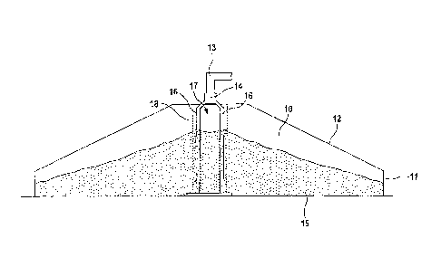
In the case of a silo as shown in figure 1 that is
intended for the storage of aluminum oxide, a silo
compartment 10 of circular cross section is enclosed by
an outer wall 11. The silo compartment 10 has a
diameter of 100 m. The outer wall is approximately 8 m
high, with the height of the silo in its center being
approximately 25 m. The silo thus has a capacity of
more than 100,000 t of aluminum oxide when it is filled
nearly up to the roof 12. Figure 1 shows the silo
filled to approximately 70% with aluminum oxide as bulk
material 15, with the filling height decreasing from
the center to the outer wall 11, commensurately with
the bulk material angle of the material. The roof 12 of
the silo has an inclination corresponding approximately
to the bulk material angle of the material.
Further bulk material 15 is fed into the silo through a
pipeline 13 opening in the silo. A distribution chamber
14 is used to distribute the bulk material 15 from the
pipeline 13 to a plurality of filler pipes 16. From the
filler pipes 16 the bulk material first passes into a
feed chamber 17 which is separated from the silo
compartment 10 by a partition wall 18. The bulk
material 15 moves from the feed chamber 17 into the
silo compartment 10 by passing through the partition
wall 18. The feed chamber 17 may be designed to be
self-supporting. Where appropriate, the feed chamber
forms an additional support for the roof 12.
The upper portion of the feed chamber 17 is illustrated
on an enlarged scale in figure 2. In each of the filler
pipes 16, a plurality of valve openings 19 are formed
one above the other. The valve openings 19 are each
constituted by an opening in the wall of the filler
pipe 16 that is closed by a flap 20. The flap 20 is
hinge-mounted on the wall of the filler pipe 16 above
the opening such that it hangs vertically downward
CA 02774813 2012-03-21
W02011/032680 - 9 - PCT/EP2010/005624
under the influence of gravity and closes the opening
in the wall of the filler pipe 16. Alternatively, a
spring force acts on the flap 20, keeping the latter in
the closed position.
The filler pipes are enclosed by the partition wall 18
which separates the feed chamber 17 from the silo
compartment 10. As indicated by the double lines, the
partition wall 18 is of stable design, with the result
that the partition wall 18 can withstand the loads
which occur in the silo. These loads are especially the
shear forces when the bulk material 15 slides downward
parallel to the partition wall 18, and compressive
forces when the bulk material 15 in the silo
compartment 10 moves in the transverse direction. The
filler pipes 16, which would themselves not withstand
this loading, are protected by the partition wall 18.
A plurality of outlet openings 21 are provided at
different heights in the partition wall 18. The outlet
openings 21 are simple perforations in the partition
wall 18 that do not feature any moving parts. The
outlet openings 21 are thus also formed in such a way
that they are not adversely affected by the shear
forces. In the cross-sectional illustration of figure
2, one outlet opening 21 corresponds to each valve
opening 19. The outlet opening 21 is in each case
arranged slightly lower than the valve opening 19 such
that bulk material, which has entered the feed chamber
17 through one of the valve openings 19, can slide into
the silo compartment 10 through the associated outlet
opening 21. As figure 3 shows, further outlet openings
22 are formed at other circumferential positions
between the filler pipes 16. The outlet openings 22 are
arranged at a different height than the outlet openings
21; however, there is a height overlap in each case.
For each filling level in the feed chamber 17, there
are thus outlet openings 21, 22 in the partition wall
CA 02774813 2012-03-21
W02011/032680 - 10 - PCT/EP2010/005624
18 through which the bulk material can slide into the
silo compartment 10. The feed chamber 17 is circular in
cross section and has a diameter of approximately 2 m.
The filler pipes 16 likewise have a circular cross
section and a diameter of approximately 20 cm.
If the silo compartment 10 in the immediate vicinity of
the feed chamber 17 has been filled with bulk material
to a certain filling height, the bulk material 15
10 thus continues to slide from the feed chamber 17 into
the silo compartment 10 until the filling level in the
feed chamber 17 is only a little higher than the
filling level in the silo compartment 10. In order to
allow further filling of the silo compartment 10, the
15 feed chamber 17 must thus have at least a filling
height corresponding to that in the silo compartment
10. Outlet openings 21, 22 in the partition wall 18 and
valve openings 19 in the filler pipes 16 which are
situated below this filling height are closed off by
the bulk material 15. The higher-up outlet openings 21,
22 in the partition wall 18 are open and freely
penetrable. The higher-up valve openings 19 in the
filler pipes 16 are closed by the flaps 20 in the
normal state. If further bulk material is now fed
through the pipeline 13 and the distribution chamber 14
to the filler pipes 16, the filler pipes 16 first fill
to a filling level corresponding to that of the feed
chamber 17. If the filling level in the filler pipes 16
rises further, the column of bulk material 15 exerts a
laterally directed force by means of which the flap 20
of the immediately higher valve opening 19 is pressed
laterally such that this valve opening 19 opens and
thus changes into the active state. The bulk material
15 can slide through the active valve opening 19 into
the feed chamber 17. There occurs a constant bulk
material flow from the distribution chamber 17 via the
filler pipes 16 and the active valve openings 19 into
the feed chamber 17. The bulk material flow generates a
CA 02774813 2012-03-21
W02011/032680 - 11 - PCT/EP2010/005624
vacuum in the filler pipes 16 which keeps closed the
valve openings 19 past which the bulk material flow
passes.
If the bulk material flow causes the filling level in
the silo compartment 10, and hence also the filling
level in the feed chamber 17, to rise, the active valve
opening 19 is covered and closed by the bulk material
in the feed chamber 17. It is not possible for any
further bulk material 15 to exit through this valve
opening 19, and the valve opening 19 becomes inactive.
Consequently, the filling level in the filler pipe 16
rises and the immediately higher valve opening 19
becomes activated.
In the embodiment of figure 4, the valve openings 19
are configured as simple perforations in the wall of
the filler pipe 16. Baffle plates 23 are mounted above
the valve openings 19. A bulk material flow falling
through the filler pipe 16 is diverted by the
respective baffle plate 23 in such a way that said flow
maintains a distance from the relevant valve opening 19
and therefore does not exit through the valve opening
19. It is only when the bulk material 15 in the filler
pipe 16 has banked up to the height of the valve
opening 19 that the bulk material 15 slides through the
valve opening 19 into the feed chamber 17.
The vertical spacing between two adjacent valve
openings 19 is approximately 30 cm. The maximum falling
height to which the bulk material 15 is subject when
passing from the filler pipes 16 into the feed chamber
17 is thus small. There is a height overlap between the
outlet openings 21, 22 in the partition wall 18, with
the result that the falling height of the bulk material
15 when it passes from the feed chamber 17 into the
silo compartment 10 is virtually zero. In the case of
the silo according to the invention, the bulk material
CA 02774813 2012-03-21
W02011/032680 - 12 - PCT/EP2010/005624
15 is thus channeled by the filler pipes 16 into the
silo compartment 10 via the feed chamber 17 without the
bulk material 15 being subject to a significant falling
height. No segregation of the bulk material 15 takes
place.