Note : Les descriptions sont présentées dans la langue officielle dans laquelle elles ont été soumises.
CA 02774909 2012-03-21
WO 2011/036532 PCT/IB2010/002352
SPOOL VALVE
TECHNICAL FIELD
100011 The invention generally relates to a spool valve for controlling the
direction of a
flow of a hydraulic fluid, and more specifically to spool for the spool valve.
BACKGROUND OF THE INVENTION
[00021 Spool valves control, i.e., switch, the direction of flow of a
hydraulic fluid by
moving a spool axially along a longitudinal axis within a bore of a valve
housing between at least
a first position and a second position. Movement of the spool opens and/or
closes fluid
communication between various ports defined by the valve housing to direct the
hydraulic fluid
along at least one of a first flow path and a second flow path.
100031 The spool includes multiple land portions that each include a diameter
substantially equal to a diameter of the bore within which the spool is
disposed. The land
portions are each configured for sealing against the bore. The various land
portions define
therebetween multiple fluid directing portions. The fluid directing portions
are in fluid
communication with the various ports defined by the valve housing, and are
sealed from each
other by the various land portions. The fluid directing portions cooperate
with the bore to define
fluid chambers, through which the hydraulic fluid flows from one port to
another.
[00041 In operation, the hydraulic fluid flows from the various ports into the
fluid
chambers, and flows along an outer surface of the various fluid directing
portions of the spool.
Accordingly, the shape of the outer surface of the fluid directing portions of
the spool directly
affects the flow characteristics of the hydraulic fluid flowing through the
fluid chambers.
SUMMARY OF THE INVENTION
[00051 In one aspect of the invention, a spool valve is disclosed. The spool
valve
includes a housing, which defines a bore extending along a longitudinal axis.
The housing
further defines a supply port, a first load port, a second load port and at
least one exhaust port.
The supply port is in fluid communication with the bore and is configured for
supplying a
hydraulic fluid to the bore. The first load port is in fluid communication
with the bore and is
CA 02774909 2012-03-21
WO 2011/036532 PCT/IB2010/002352
configured for directing the hydraulic fluid along a first flow path. The
second load port is in
fluid communication with the bore and is configured for directing the
hydraulic fluid along a
second flow path. The at least one exhaust port is in fluid communication with
the bore and is
configured for exhausting the hydraulic fluid from the housing. A spool is
disposed within said
bore and moveable between at least a first position and a second position. The
first position
opens fluid communication between the supply port and the first load port,
opens fluid
communication between the second load port and the at least one exhaust port,
and closes fluid
communication between the supply port and the second load port. The second
position opens
fluid communication between the supply port and the second load port, opens
fluid
communication between the first load port and the at least one exhaust port,
and closes fluid
communication between the supply port and the first load port. The spool
includes a supply
portion disposed axially along the longitudinal axis between a first land
portion and a second land
portion. The supply portion defines a truncated pseudosphere configured for
directing the
hydraulic fluid to the first load port when the spool is in the first position
and configured for
directing the hydraulic fluid to the second load port when the spool is in the
second position.
[0006] In another aspect of the invention, a spool for a spool valve is
disclosed. The
spool includes a first end and a second end spaced along a longitudinal axis
from the first end. A
first land portion, a second land portion, a third land portion disposed
between the first end and
the first land portion and a fourth land portion disposed between the second
land portion and the
second end. Each of the first land portion, the second land portion, the third
land portion and the
fourth land portion are configured for sealing against a bore of a valve
housing. A supply portion
is disposed axially along the longitudinal axis between the first land portion
and the second land
portion. A first return portion is disposed axially along the longitudinal
axis between the third
land portion and the first land portion. A second return portion disposed
axially along the
longitudinal axis between the fourth land portion and the second land portion.
The supply
portion defines a truncated pseudosphere configured for selectively directing
a hydraulic fluid to
one of a first load port and a second load port of the valve housing.
[0007] Accordingly, the shape of the spool, and more specifically the shape of
the supply
portion of the spool, smoothly directs the flow of the hydraulic fluid from
the supply port to one
2
CA 02774909 2012-03-21
WO 2011/036532 PCT/1B2010/002352
of the first load port and the second load port, which reduces a hydraulic
force generated by the
hydraulic fluid that acts on the spool. Reducing the hydraulic force acting on
the spool allows the
spool to be moved with less effort.
[0008] The above features and advantages and other features and advantages of
the
present invention are readily apparent from the following detailed description
of the best modes
for carrying out the invention when taken in connection with the accompanying
drawings.
BRIEF DESCRIPTION OF THE DRAWINGS
[0009] Figure 1 is a schematic cross sectional view of a spool valve showing a
first
embodiment of a spool in a first position.
[0010] Figure 2 is a schematic cross sectional view of the spool valve showing
the first
embodiment of the spool in a second position.
[0011] Figure 3 is a schematic cross sectional view of an alternative
embodiment of the
spool.
[0012] Figure 4 is an enlarged fragmentary schematic cross sectional view of
the first
embodiment of the spool.
[0013] Figure 5 is an enlarged fragmentary schematic cross sectional view of a
second
alternative embodiment of the spool.
[0014] Figure 6 is an enlarged fragmentary schematic cross sectional view of a
third
alternative embodiment of the spool.
DESCRIPTION OF THE PREFERRED EMBODIMENTS
[0015] Referring to Figures 1 and 2, wherein like numerals indicate like parts
throughout
the several views, a spool valve is shown generally at 20. The spool valve 20
directs a flow of a
hydraulic fluid along at least one of a first flow path, shown in Figure 1,
and a second flow path,
shown in Figure 2.
[0016] The spool valve 20 is part of a hydraulic system. The hydraulic system
may
include a pump (not shown) for pressurizing and circulating the hydraulic
fluid, the spool valve
20 for directing the flow of the hydraulic fluid, a motor (not shown) for
converting the flow of
3
CA 02774909 2012-03-21
WO 2011/036532 PCT/IB2010/002352
pressurized hydraulic fluid into work, and a tank (not shown) for storing
excess hydraulic fluid
and circulating the hydraulic fluid back to the pump.
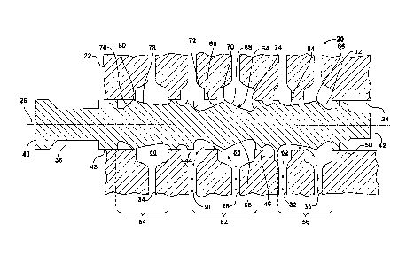
[00171 The spool valve 20 includes a housing 22. The housing 22 defines a bore
24,
which extends along a longitudinal axis 26. The housing 22 may be configured
in any suitable
manner for the specific situation for which it is intended. Accordingly, it
should be appreciated
that the housing 22 may be configured and/or shaped differently than shown. As
shown, the
housing 22 further defines a supply port 28, a first load port 30, a second
load port 32 and at least
one exhaust port, 34, 36. The supply port 28 is in fluid communication with
the bore 24, and is
configured for supplying the hydraulic fluid to the bore 24. The first load
port 30 is in fluid
communication with the bore 24, and is configured for directing the hydraulic
fluid from the bore
24, along the first flow path. The second load port 32 in is fluid
communication with the bore 24,
and is configured for directing the hydraulic fluid from the bore 24, along
the second flow path.
The at least one exhaust port 34, 36 is in fluid communication with the bore
24, and is configured
for exhausting the hydraulic fluid from the housing 22 for return back to the
tank. As shown, the
at least one exhaust port includes a first exhaust port 34 and a second
exhaust port 36.
[00181 The spool valve 20 includes a spool 38, which is moveably disposed
within the
bore 24. The spool 38 is moveable between at least a first position, shown in
Figure 1, and a
second position, shown in Figure 2. The first position opens fluid
communication between the
supply port 28 and the first load port 30, opens fluid communication between
the second load
port 32 and the second exhaust port 36, and closes fluid communication between
the supply port
28 and the second load port 32. The second position opens fluid communication
between the
supply port 28 and the second load port 32, opens fluid communication between
the first load
port 30 and the first exhaust port 34, and closes fluid communication between
the supply port 28
and the first load port 30. It should be appreciated that the housing 22 and
spool 38 may be
configured differently than shown, and that the first position and the second
position may operate
to open and/or close fluid communication in a sequence different than shown or
described herein.
[00191 The spool 38 includes a first end 40 and a second end 42. The second
end 42 is
spaced along the longitudinal axis 26 from the first end 40. As shown, the
spool 38 further
includes a first land portion 44, a second land portion 46, a third land
portion 48 and a fourth land
4
CA 02774909 2012-03-21
WO 2011/036532 PCT/IB2010/002352
portion 50. The first land portion 44 and the second land portion 46 are
disposed near an
approximate middle of the spool 38, with the first land portion 44 disposed
nearer the first end 40
than the second end 42, and the second land portion 46 disposed nearer the
second end 42 than
the first end 40. The third land portion 48 is disposed between the first end
40 and the first land
portion 44. The fourth land portion 50 is disposed between the second land
portion 46 and the
second end 42.
[00201 Each of the first land portion 44, the second land portion 46, the
third land portion
48 and the fourth land portion 50 include a diameter that is substantially
equal to a diameter
defined by the bore 24. Additionally, each of the first land portion 44, the
second land portion
46, the third land portion 48 and the fourth land portion 50 are configured
for sealing against the
bore 24.
[00211 The spool 38 further includes a supply portion 52, a first return
portion 54 and a
second return portion 56. The supply portion 52 cooperates with the bore 24 to
define a supply
chamber 58 therebetween, into which the hydraulic fluid is directed from the
pump. The first
return portion 54 cooperates with the bore 24 to define a first chamber 60.
The second return
portion 56 cooperates with the bore 24 to define a second chamber 62.
100221 The supply portion 52 is disposed axially along the longitudinal axis
26 between
the first land portion 44 and the second land portion 46, and is disposed
nearer an approximate
midsection of the spool 38. As shown in Figure 1, the first return portion 54
is disposed to the
left of the supply portion 52 between the supply portion 52 and the first end
40. More
specifically, the first return portion 54 is disposed between the third land
portion 48 and the first
land portion 44. As shown in Figure 1, the second return portion 56 is
disposed to the right of the
supply portion 52 between the supply portion 52 and the second end 42. More
specifically, the
second return portion 56 is disposed between the second land portion 46 and
the fourth land
portion 50.
[00231 At least part of the supply portion 52 defines a truncated pseudosphere
64. As is
known, a pseudosphere is commonly defined as a constant negative surface
generated by
revolving a tractrix about its asymptote. The truncated pseudosphere 64
includes the shape of a
pseudosphere with the opposing distal ends truncated. The truncated
pseudosphere 64 is centered
CA 02774909 2012-03-21
WO 2011/036532 PCT/IB2010/002352
at a midsection of the supply portion 52. The truncated pseudosphere 64
includes a first half 66
that is configured for directing the hydraulic fluid to the first load port 30
when the spool 38 is in
the first position, and includes a second half 68 that is configured for
directing the hydraulic fluid
to the second load port 32 when the spool 38 is in the second position.
[00241 As described above, the truncated pseudosphere 64 includes an outer
surface 65
having a constant negative curvature. Additionally, the first half 66 of the
truncated
pseudosphere 64 defines a first inverse radius (1/R) and the second half 68 of
the truncated
pseudosphere 64 defines a second inverse radius (1/R). The first inverse
radius is equal to the
second inverse radius.
100251 The truncated pseudosphere 64 includes a ridge 70, which is disposed at
the
midsection of the supply portion 52. Due to the scale of Figures 1 and 2, the
ridge 70 is shown in
cross section as a point, and therefore is shown defining an annular linear
ring extending about a
periphery of the spool 38. However, referring to Figure 4, the ridge 70 may
define a flat face 71,
which extends along the longitudinal axis a pre-determined distance. Referring
also to Figures 5
and 6, alternative embodiments of the ridge 70 are shown. The pre-determined
distance may
include any distance suitable to permit manufacture and measurement of the
diameter of the ridge
70. The first half 66 and the second half 68 of the truncated pseudosphere 64
are mirror images
of each other, mirrored across the ridge 70, perpendicular to the longitudinal
'axis 26 and are
symmetrically disposed about the midsection of the supply portion 52. The
ridge 70 includes a
diameter that is greater than a diameter defined by any other section of the
truncated
pseudosphere 64. In other words, the diameter of the ridge 70 is the largest
diameter defined by
the truncated pseudosphere 64.
[00261 The supply portion 52 further includes a first curve portion 72 and a
second curve
portion 74. The first curve portion 72 is disposed axially along the
longitudinal axis 26 between
the first half 66 of the truncated pseudosphere 64 and the first land portion
44. The first curve
portion 72 defines a diameter that continuously decreases in size along the
longitudinal axis 26,
when measured in a direction moving from the first land portion 44 toward the
first half 66 of the
truncated pseudosphere 64. The second curve portion 74 is disposed axially
along the
longitudinal axis 26 between the second half 68 of the truncated pseudosphere
64 and the second
6
CA 02774909 2012-03-21
WO 2011/036532 PCT/IB2010/002352
land portion 46. The second curve portion 74 defines a diameter that
continuously decreases in
size along the longitudinal axis 26, when measured in a direction moving from
the second land
portion 46 toward the second half 68 of the truncated pseudosphere 64.
Accordingly, it should be
appreciated that the length of the supply portion 52 of the spool 38 along the
longitudinal axis 26
includes the first curve portion 72, the truncated pseudosphere 64 and the
second curve portion
74. Additionally, it should be appreciated that the diameter of the supply
portion 52 when
measured in a direction moving from the first land portion 44 toward the
second land portion 46
decreases in size along the first curve portion 72, increases in size along
the first half 66 of the
truncated pseudosphere 64, decreases in size along the second half 68 of the
truncated
pseudosphere 64 and increases in size along the second curve portion 74.
[0027] The first return portion 54 is configured for directing the hydraulic
fluid from the
first load port 30 to the at least one exhaust port when the spool 38 is in
the second position.
More specifically, the first return portion 54 is configured for directing the
hydraulic fluid from
the first load port 30 to the first exhaust port 34.
[0028] The first return portion 54 includes a first outer portion 76, a first
inner portion 78
and a first annular crest 80. The first annular crest 80 is disposed between
the first inner portion
78 and the first outer portion 76. The first outer portion 76 includes a
continuously increasing
diameter along the longitudinal axis 26 when measured along the longitudinal
axis 26 in a
direction from the third land portion 48 toward the first annular crest 80.
The first inner portion
78 includes a continuously decreasing diameter when measured along the
longitudinal axis 26 in
a direction from the first annular crest 80 toward the first land portion 44.
Accordingly, the first
inner portion 78 and the first outer portion 76 each include a rate of
diametric change, i.e., a rate
of change of the diameter of the first inner portion 78 and the first outer
portion 76 respectively,
measured along the longitudinal axis 26. The rate of diametric change of the
first outer portion
76 along the longitudinal axis 26 greater than the rate of diametric change of
the first inner
portion 78. In other words, the diameter of the first outer portion 76
decreases in size at a faster
rate than the first inner portion 78 when measured over a common distance
along the longitudinal
axis 26.
7
CA 02774909 2012-03-21
WO 2011/036532 PCT/IB2010/002352
[0029] The first return portion 54 and the second return portion 56 are mirror
images of
each other, mirrored across the midsection of the supply portion 52, i.e., the
ridge 70 of the
supply portion 52, transverse to the longitudinal axis 26. Accordingly, the
first return portion 54
and the second return portion 56 are symmetrical relative to each other about
the midsection of
the supply portion 52.
[0030] The second return portion 56 is configured for directing the hydraulic
fluid from
the second load port 32 to the at least one exhaust port when the spool 38 is
in the first position.
More specifically, the second return portion 56 is configured for directing
the hydraulic fluid
from the second load port 32 to the second exhaust port 36.
[0031] The second return portion 56 includes a second outer portion 82, a
second inner
portion 84 and a second annular crest 86. The second annular crest 86 is
disposed between the
second inner portion 84 and the second outer portion 82. The second outer
portion 82 includes a
continuously increasing diameter along the longitudinal axis 26 when measured
along the
longitudinal axis 26 in a direction from the fourth land portion 50 toward the
second annular crest
86. The second inner portion 84 includes a continuously decreasing diameter
when measured
along the longitudinal axis 26 in a direction from the second annular crest 86
toward the second
land portion 46. Accordingly, the second inner portion 84 and the second outer
portion 82 each
include a rate of diametric change, i.e., a rate of change of the diameter of
the second inner
portion 84 and the second outer portion 82 respectively, measured along the
longitudinal axis 26.
The rate of diametric change of the second outer portion 82 along the
longitudinal axis 26 is
greater than the rate of diametric change of the second inner portion 84. In
other words, the
diameter of the second outer portion 82 decreases in size at a faster rate
than the second inner
portion 84 when measured over a common distance along the longitudinal axis
26.
[0032] Referring to Figure 3, an alternative embodiment of the spool is shown
generally
at 188. Elements of the alternative embodiment of the spool 188 that are
identical to the elements
of the first embodiment of the spool 38, described above, are identified by
the same reference
numeral increased by one hundred. For example, the first land portion,
identified by the
reference numeral 44 in the first embodiment of the spool 38 is identified by
the reference
numeral 144 in the alternative embodiment of the spool 188, the first end,
identified by the
8
CA 02774909 2012-03-21
WO 2011/036532 PCT/IB2010/002352
reference numeral 40 in the first embodiment of the spool 38 is identified by
the reference
numeral 140 in the alternative embodiment of the spool 188, the second end,
identified by the
reference numeral 42 in the first embodiment of the spool 38 is identified by
the reference
numeral 142 in the alternative embodiment of the spool 188, and the third land
portion, identified
by the reference numeral 48 in the first embodiment of the spool 38 is
identified by the reference
numeral 148 in the alternative embodiment of the spool 188.
[00331 Within the alternative embodiment of the spool 188, the first land
portion 144 and
the second land portion 146 each include a frustoconical portion 190. The
frustoconical portion
190 of each of the first land portion 144 and the second land portion 146 each
include a diameter
that decreases in size when measured along the longitudinal axis 126 in a
direction directed
inward toward the supply portion 152. As such, the diameter of the
frustoconical portion 190 of
the first land portion 144 decreases in size when measured along the
longitudinal axis 126 in a
direction from left to right on paper, i.e., from the first return portion 154
toward the supply
portion 152. Similarly, the diameter of the frustoconical portion 190 of the
second land portion
146 decreases in size when measured along the longitudinal axis 126 in a
direction from right to
left on paper, i.e., from the second return portion 156 toward the supply
portion 152.
[00341 While the best modes for carrying out the invention have been described
in detail,
those familiar with the art to which this invention relates will recognize
various alternative
designs and embodiments for practicing the invention within the scope of the
appended claims.
9