Note : Les descriptions sont présentées dans la langue officielle dans laquelle elles ont été soumises.
CA 02776720 2012-05-15
METHOD AND APPARATUS FOR STARTING MOVING ITEMS
INTO A PROCESSING MACHINE
This invention involves apparatus and methods useful in the manufacture of
continuous
fiber and/or continuous fiber strand products including chopped, wound and/or
otherwise
processed fiber(s) and/or fiber strand(s), and more particularly for starting
new fiber(s) and/or
new strand(s) of fibers into a puller or chopper or winder, etc. using a
mechanical apparatus
while other fibers and/or strand(s) of fibers are running into the chopper,
puller, winder, etc. and
being chopped, pulled or wound, without disturbing those running fiber(s) or
strand(s) of fibers.
BACKGROUND
In the manufacture of chopped fibers from continuous fiber(s), such as glass
fiber,
molten glass is extruded through tips or holes in the bottom of a bushing,
forming beads at the
end of the tips or the exposed side of the holes. Once beads of the molten
glass have formed at
the end of the tips or holes and when the beads reach a certain size, the
forces of, surface
tension, wetting, and viscosity of the molten material holding the bead to the
bottom of the tips
or holes are overcome by gravity and the beads fall, each bead trailing a
continuous, coarse,
primary fiber behind which is attached at its other end to the molten glass in
the tip or hole from
which the bead came. These primary fibers are usually sprayed with a cooling
water mist after
they move out of the immediate area below the tip plate of the bushing in a
known manner. The
primary fibers continue to form as the weight of the beads and primary fibers
pull down through
holes in the floor of the fiber forming room and into a waste system, usually
located in a
basement or lower level.
Once all of the tips or holes have thus "beaded out", the array of primary
fibers from that
bushing is ready to be gathered into a fiber bundle, i. e. a strand, and
started into a chopper or
other device that will pull the strand of fibers at a high speed to attenuate
the molten
meniscuses forming the fibers very near the tips or holes to a desired fiber
diameter and then
will also chop, wind or otherwise process the fibers, strand or strands of
fibers into a desired
product form. Normally, the fibers will also be pulled over or past an
applicator that will apply a
coating of chemical sizing onto the wet fibers prior to chopping in a known
manner.
1
CA 02776720 2012-05-15
After a bushing has been in service a few weeks or months, the tips get out of
alignment with
the cooling means and often a few tips will have a lower molten glass flow
rate than the other
tips. To accelerate the bead down time of these tips the operator will move
the array of primary
fibers back and forth to attach the slow beads to primary fibers and pull them
down to get a
primary fiber from all tips and a strand ready to start. Until the primary
fibers are started into a
puller, chopper, winder, etc., they usually continue to move and fall into a
scrap pit or area
beneath the floor of the fiber forming room.
For a number of reasons, fibers tend to break all too frequently, usually near
the end of
the tips in the bushings. Particularly with E type glass, when one fiber
breaks it is most always
only a matter of a minute or a few minutes until the entire array of fibers
from the bushing is
broken out and then generating primary fibers scrap. Even in cases where
broken fibers do not
form beads or break out the remainder of the bushing, by design, it is
nevertheless prudent to
break out the entire bushing and restart it after a small number of fibers
have broken to
maximize efficiency and to reduce variation in the product being produced.
The portion of the continuous fiber making process of starting a strand of
fibers from all
of the tips of a bushing into choppers or other processing equipment is often
done by hand and
is labor intensive. It also can cause minor injuries to the hands and is
usually abrasive to the
hands. Thus, it is desirable to enhance this procedure by making it easier and
more effective to
avoid injuries, hand abrasion, and false starts and to improve productivity
thus reducing labor
cost and overhead costs by increasing the percentage of time each bushing is
producing good
chopped fiber products and to reduce raw material and energy costs by reducing
primary fiber
scrap.
SUMMARY
The present invention comprises apparatus and methods for eliminating these
problems
existing in the starting of one or more new continuous fibers and one or more
new continuous
strands of fibers, hereinafter referred to as "fiber(s)", into a chopper, a
winder or other fiber(s)
processing equipment. The invention includes apparatus for manipulating slow
to rapidly moving
fiber(s), i.e. for changing the paths of the fiber(s) for starting new
fiber(s) into a chopper, a
winder or other fiber(s) processing equipment. The winder can be a direct
wound winder on
which the fiber(s) are wound onto a mandrel, a cake winder in which the
fiber(s) are wound onto
2
CA 02776720 2012-05-15
a thin tube of paper or plastic, a bobbin winder in which the fiber(s) are
wound onto a bobbin,
spool or other known fiber(s) holder. Most any type of chopper for chopping
fiber(s) into short
lengths is included as shown in the drawings. Other fiber(s) processing
equipment can include
fiber(s) coating, blending, twisting, braiding or other treating/processing
equipment.
The fiber(s) can be of any material including various types of glass and/or
various
polymers, co-polymers and/or homo-polymers, and/or natural material, and/or
various kinds of
ceramics, and/or various kinds of carbon, and/or various metals and any
combination thereof.
Typically, the diameters of the fibers in the fiber(s) will be in the range of
about 5 microns to
about 30 microns, but the diameters are not critical to the invention so can
be larger or smaller
than this range. By continuous fiber(s) is meant fiber(s) having long lengths,
typically tens,
hundreds and even thousands of feet long, as contrasted with staple fiber that
are much shorter.
A strand of fibers can contain staple fibers, but they must be twisted to make
a continuous
strand, such as wool yarn, cotton thread, and like fibrous strands of staple
fibers.
The invention comprises an apparatus particularly useful in a process for
making
continuous fiber products, such as chopped or wound fiber(s), coated fiber(s)
or other
processed fiber(s). Typically the lengths of the chopped fiber are in the
range of about 0.125 to
inches long, more typically about 0.25 to about 4 inches long with lengths
averaging 1.25, 1,
0.75, 0.5, 0.25 and 0.16 inch(es) being most common. While there are instances
where an
individual fiber is started into the chopper, it is more typical to use the
invention on strands of
fibers containing from about 400 to about 6000 or more fibers per strand,
particularly about
2400 or more fibers per strand. The fibers need not come from a fiberizing
bushing, though that
is often the process, but they can be pulled from a wound package, cake or
spool or some other
type of fiber holding or forming device. The types of wound products that the
apparatus of the
invention is useful in making include wound cakes, packages, bobbins, etc. of
fiber(s) direct
roving, manufactured roving (from cakes), cakes, yarn with or without twists,
etc. The apparatus
of the invention can also be used in conventional processes for making coated
fiber(s) products,
i.e. in any process where it is necessary for an operator to manipulate the
fiber(s) with one or
more hands to start new fiber(s) into the process and to adjust the fiber(s)
with his hand(s) after
the new fiber(s) are started, but not yet in the desired path.
The fiber(s) manipulating apparatus of the invention comprises a rotatable and
movable
shoe comprising a shaped surface, groove or valley for supporting and
constraining the new
3
CA 02776720 2012-05-15
fiber(s) and the path of slow running, but soon rapidly running, fiber(s), one
or more
mechanisms for moving the shoe in one or more directions including
horizontally, generally
horizontally, clockwise and counter-clockwise for rotating the shoe including
a rotary actuator,
the shape of the shoe being such that when sufficiently rotated, the running
fiber(s) will no
longer be supported and constrained by the shoe and can move away from the
shoe to a
different and desired path, a movable and pivoting finger, guide rod, one or
more mechanisms
for moving the guide rod or finger in one or more directions including
horizontally, generally
horizontally and pivoting clockwise and pivoting counter-clockwise, a further
mechanism for
moving the shoe horizontally or generally horizontally in a direction
perpendicular and generally
perpendicular to the direction the shoe and the finger or guide rod move, and
a controller for
operating each of the mechanisms . The apparatus of the invention can also
comprise, or be
used with, a separator guide or roll having one or more fiber(s) grooves
thereon and/or an
accelerating roll that will accelerate the speed of the slow running fiber(s)
up to a rapid speed
when the new fiber(s) are laid onto the upper surface of the accelerating roll
and a accelerating
switch or sensor actuated, or when the new fiber(s) are wound on a rotating
mandrel, put into a
set of pull rolls or other pulling device.
By supporting and constraining the fiber(s) is meant with respect to a
contacting surface
of the shoe, with respect to a horizontal or generally horizontal axis of the
shoe, while allowing
the fiber(s) to run slowly and then rapidly over the contacting surface in a
direction
perpendicular or generally perpendicular to the horizontal or generally
horizontal axis of the
shoe, typically being a valley or groove in the material of the shoe and/or in
the material of a
projection such as a hooknose, curved finger, and the like. By shoe is meant
any shape that will
accomplish the function of the tapered shoes disclosed herein. By generally
horizontal or
horizontally is meant within about 10 degrees from the horizontal, by
generally perpendicular is
meant from about 5 degrees to about 10 degrees from perpendicular and by
generally vertical
or vertically is meant within about 10 degrees from vertical. By near is meant
being within about
one inch. By slow or slowly running or moving is meant moving in the direction
of the fiber(s) at
a rate up to about 200 or 300 feet per minute (ft./min.) and by rapidly moving
or running is
meant a speed in the range of up to about 200 or 300 ft./min. to 15,000
ft./min or higher, more
typically at least 300 or 500 ft./min. to 10,000 ft./min or higher, most
typically at least about 400-
750 ft./min. to as high as 1000, 1500, 2000, 5000, 10,000, 15,000 ft./min.,
anywhere in between
any of these speeds or even at higher speeds. The fiber or fiber strand, i.e.
strand or strands
containing many fibers, usually more than 100, 200, 400, 800, 1600, 2,000,
4,000, 6,000 fibers,
4
CA 02776720 2012-05-15
any number between these numbers and even many more than 6000 fibers, are
usually wet, but
need not be. Normally the fiber(s) and/or fiber strand(s) move slowly when the
operator first
places the fiber(s) and/or fiber strand(s) onto the apparatus of the invention
and in a short time
the fiber(s) and/or fiber strand(s) are accelerated to a much higher speed,
i.e. to a speed in the
ranges or upper part of the ranges stated above. By slow or slowly running is
meant the initial
speed of the strand when placed onto the apparatus of the invention, normally
in the range of
about 50-250 ft./min. or slightly higher (walking speed of an operator).
The fiber or fiber(s), especially when they are glass fiber(s) usually are
coated with a wet
chemical sizing of any of many well known fiber sizing compositions, usually
containing a
lubricant to protect the surface of the fiber(s), and optionally a film former
and/or a bond
enhancing material to enhance the bond to an intended matrix the fibers will
be placed in, the
sizing chemicals usually dispersed in water or another solvent. By fiber(s)
and/or fiber strand(s)
is meant one or more fibers, one or more fiber strands, and one or more
strands each
containing a plurality of fibers, the latter two categories being the same. By
fibers is meant to
include fiber(s) of any material including glass, a polymer, a co-polymer, a
homo-polymer,
natural material including cotton, wool, flax, etc., metal, ceramic (other non-
organic materials),
carbon, ceramet (ceramic-metal mixtures) and any mixtures thereof.
The shoe or tapered shoe can be of many shapes so long as that it functions to
hold,
without significantly slowing or impeding the slow and rapid movement of the
fiber(s), causing
significant drag or friction on the moving fiber(s) in some orientations of
its rotation and releases
the rapidly moving fiber(s) in other orientations of its rotation. By holding
or sustaining is meant
restraining the path of the rapidly moving fiber(s) within about 0.25 inch on
the fiber(s) entry side
and the fiber(s) and/or fiber strand(s) exit side of the tapered shoe. Any
mechanism for holding
and rotating the tapered shoe is suitable, but a rotatable shaft fixed snugly
on one end to the
shoe and on or near the other end to a servo motor for rotating the tapered
shoe is most
preferred, less preferred being a shaft snugly attached to the tapered shoe on
one end, passing
through a rotatable bearing spaced from the tapered shoe for holding the shaft
and a servo
motor or other mechanism contacting the shaft near or at its other end for
rotating the shaft in
the desired manner. The rotating mechanism can include one or more pulleys,
sprockets, belts,
bands or other known drive elements, or a rotatable roller in contact with an
outer surface or the
shaft or the tapered shoe, the rotatable roller rotated by a drive of some
known type, such as a
servo motor. The drive or motor turning the generally horizontally mounted
shaft can be
CA 02776720 2012-05-15
mounted on a frame of the apparatus, as can the one or more mechanisms moving
the finger or
guide rod. The guide rod can be any material having reasonable wear
resistance, preferably in
the form of a hollow or solid rod having a circular cross-section. At least
the surface of the finger
or guide rod should be of a material that produces a low level of friction
with the moving fiber(s)
that are in contact with the finger or guide rod.
The invention also includes a system for starting moving fiber(s) into a fiber
processing
machine such as a chopper, a winder or other known fiber(s) processing
machine, the system
including the above moving fiber(s) supporting and manipulating apparatus. The
chopper can be
any chopper machine that can continuously separate the fiber(s) into short
lengths, and the
winder can be any winder that winds long lengths of the fiber(s) into packages
such as roving
packages, cakes, bobbins, and the like.
The invention also includes methods of using the apparatus of the invention to
manipulate the rapidly moving fiber(s) and/or the fiber strand(s), and methods
of manipulating
the rapidly moving fiber(s) or the fiber strand(s) into a chopper, winder or
other piece of fiber(s)
processing equipment. Also, methods of making chopped fiber(s) and of making
wound fiber(s)
products using the apparatus of the invention are included in the invention.
The manipulation, in
many embodiments of the invention, comprises placing slow moving fiber(s) onto
a surface of a
fiber(s) sustaining surface of a fiber(s) shoe, such as a tapered shoe, and
onto a rotating roll
that will pull and accelerate the fiber(s) to a rapid speed, and using the
strand manipulator by
first rotating the guide finger to a vertical or generally vertical position
with the end of the guide
finger in an upper position above the rapidly moving fiber(s), second moving
the guide finger,
shoe and fiber(s) horizontally or generally horizontally, and perpendicular or
generally
perpendicular to the direction in which the fiber(s) are moving rapidly, to a
location beneath and
in alignment with a desired groove in a fiber(s) guide or guide roll, third
moving the shoe
horizontally or generally horizontally in a direction parallel to the desired
groove in the guide or
guide roll to raise the rapidly moving fiber(s) vertically, fourth rotate the
shoe to release the
fiber(s) from the shoe allowing the fiber(s), with the aid of the guide finger
or guide rod, to enter
the desired groove on the fiber(s) guide or guide roll, returning the shoe and
the guide finger or
guide rod to their original positions. These methods can include other steps
to facilitate feeding
the fiber(s) into a fiber(s) chopper, winder or other type of fiber(s)
processing equipment.
6
CA 02776720 2012-05-15
The above described inventions increases the productivity of the manufacturing
operations by reducing operator errors and by freeing up the operators for
more timely attention
to the bushings operation, starting new fiber(s) and cleaning of the equipment
to avoid sizing
buildup that cause breakouts. The inventions also provide for better working
conditions by being
more safe and less abrasive to the hands. Also, importantly, the invention is
much easier for a
new operator to become proficient in starting new strands as the prior art
technique requires
considerable time for new operators to develop the manual dexterity necessary
to achieve
successful starts, requiring two or more tries, wasting precious time while
producing scrap until
the new operators finally are developed - some never do and have to seek other
tasks or a new
job.
When the word "about" is used herein it is meant that the amount or condition
it modifies
can vary some beyond that stated so long as the advantages of the invention
are realized.
Practically, there is rarely the time or resources available to very precisely
determine the limits
of all the parameters of one's invention because to do so would require an
effort far greater than
can be justified at the time the invention is being developed to a commercial
reality. The skilled
artisan understands this and expects that the disclosed results of the
invention might extend, at
least somewhat, beyond one or more of the limits disclosed. Later, having the
benefit of the
inventors' disclosure and understanding the inventive concept and embodiments
disclosed
including the best mode known to the inventor, the inventor and others can,
without inventive
effort, explore beyond the limits disclosed to determine if the invention is
realized beyond those
limits and, when embodiments are found to be without any unexpected
characteristics, those
embodiments are within the meaning of the term "about" as used herein. It is
not difficult for the
artisan or others to determine whether such an embodiment is either as
expected or, because of
either a break in the continuity of results or one or more features that are
significantly better
than reported by the inventor, is surprising and thus an unobvious teaching
leading to a further
advance in the art.
BRIEF DESCRIPTION OF THE DRAWINGS
Figure 1 is a front view of a fiber forming partial leg in a typical prior art
glass fiber
forming room and showing a prior art fiber(s) chopper.
Figure 2 is a plan view of the prior art system shown in Fig. 1.
7
CA 02776720 2012-05-15
Figure 3A is a front view of a different prior art chopper useful with the
invention
Figure 3B is a perspective view of another prior art chopper useful with the
invention
Figure 4A is a perspective view of still another prior art chopper useful with
the invention.
Figure 4B is a front view of still another prior art chopper useful with the
invention.
Figure 5 is a front view of the apparatus of the invention and a partial front
view of the
chopper shown in Figs. 1 and 2, but with elements 22 and 24 removed.
Figure 5A is a front view similar to Fig. 5, but showing new fiber(s) being
started into the
chopper using the apparatus of the invention to make chopped fibers.
Figure 6 is a partial front view of the apparatus shown in Fig. 5A holding
moving new
fiber(s) in a first position.
Figure 7 is a partial plan view of Fig. 5A.
Figure 8 is a partial plan view showing the moving new fiber(s) in a second
position.
Figure 9 is a partial plan view showing the moving new fiber(s) in a third
position.
Figures 10 - 13 are partial front views showing positions in sequential steps
of using the
invention.
Figures 14 and 15 are partial plan views of some sequential steps of using the
invention.
Figure 16 is a front view showing the use of the apparatus of the invention in
a different
fiber(s) processing system and method to make different fiber products.
Figure 17 A is a rear perspective view of a shoe used in the invention to hold
the moving
new fiber(s).
8
Figure 17B is a rear view of the shoe of Fig. 17A.
Figure 17C is a plan view of the shoe of Fig. 17A.
Figure 17D is an end view of the shoe of Fig. 17A.
Figure 17E is an end view of the shoe of Fig. 17A with a portion of the shoe
cut away to
show its interior.
Figure 17F is a bottom view of the shoe of Fig. 17A.
Figure 17G is a front perspective view of the shoe of Fig. 17A
Figure 17H is a front view of the shoe of Fig. 17A.
Figure 18A is an end view of a tapered shoe usable in the invention.
Figure 18B is an end view of the tapered shoe of Fig. 18A with fiber(s) being
supported
and constrained.
Figure 18C is a front view of the tapered shoe of Fig. 18A, but in a different
and fiber(s)
releasing orientation.
Figure 19 is a perspective view of a preferred apparatus of the invention.
Figure 20 is a plan view of the apparatus shown in Fig. 19.
Figure 21 is an end view of the apparatus shown in Figs. 19 and 20.
Detailed Description of The Best Mode and Some Embodiments
Typical apparatus and methods used in the industry to make continuous chopped
fiber
products are disclosed in United States Patent Nos. 4,194,896, 4,576,621,
5,935,289,
5,970,837 and 7,252,026.
9
CA 2776720 2018-06-12
In a typical method an operator would stand below and in front of a fiber
forming bushing to be
restarted. If a part of the bushing is still running good fibers, the operator
would break out that
portion. As soon as all of the tips have beaded out and primary fibers are
being generated from
all of the tips, the operator gathers the array of fibers together, often
several thousand fibers,
into a bundle or strand, cuts or breaks the strand to form an end and pulls
the fiber strand down
such that the fiber array is against or near a sizing applicator, then pulls
the strand under a pad
wheel or guide with a curved surface located below the bushing and the sizing
applicator, and
walks the strand, pulling it, towards a puller, such as a chopper or a winder,
and feeds the new
strand into the pulling mechanism whereby the strand is pulled at the proper
attenuation speed
and, in the case of a chopper, is moved into a path running to the nip between
a rotating idler
roll and a counter rotating backup roll, or alternatively, directly into a
path towards the nip
between the rotating backup roll and a counter rotating blade roll. The idler
roll and backup roll
pull the strand(s) of fibers and the blade roll and backup roll continuously
pull and/or chop the
rapidly moving fiber strand(s) into chopped fibers of desired length for use
in reinforced plastics,
non-woven fiber glass mats, etc. As used herein, the fiber(s) can be a single
fiber, a plurality of
fibers, a single strand of fibers and/or a two or more strands of fibers as
explained above in the
Summary.
In a typical operation each operator may have responsibility for 10 to 20 or
more
bushings and each bushing start may require walking at least 5-40 feet to get
the strand to the
puller, chopper, winder, or other fiber(s) and/or strand(s) processing
equipment, and to walk
back to the position or the next position needing attention or restarting.
With many bushings
typically breaking out (at least 20 fibers broken) at least 0.1-4 or more
times per hour, especially
when the glass quality varies from normal, the operator either doesn't have
time to start each
bushing as soon as necessary for most efficient operation, or the operator
becomes tired and
doesn't get the bushings restarted in a timely manner. This resultant loss of
efficiency and the
desire to reduce the labor, material, energy and overhead costs in this
process makes it
desirable to aid the strand restarting process, the most labor intensive
portions of these
processes, wherever practical. The prior art apparatus and methods of using
cause frequent
minor injuries and false/aborted strand starts, both resulting in lowered
productivity. Therefore, it
is very desirable to eliminate these problems. The potential injury and hand
abrasion and
pinching problems associated with starting new fiber strands has grown more
serious with the
continued expansion of the number of fibers in the strands because of the
development of larger
CA 2776720 2018-06-12
CA 02776720 2012-05-15
and larger output bushings, each producing thousands of fibers, particularly
upwards from about
2400 to more than 6000 fibers.
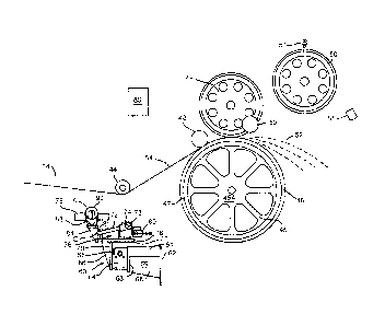
Figures 1 and 2 show a pertinent portion of a typical prior art system for
making
continuous fibers and then chopping the fibers, e.g. glass, polymer(s), co-
polymer(s), homo-
polymer(s) fibers, or fibers of mixtures of two or more such materials. Glass
fibers will be used
as an example. Molten glass is fed from a furnace and forehearth (not shown)
into a plurality of
electrically heated fiberizing bushings 2, each bushing having a bottom plate
with holes and
hollow tips therein through which the molten glass is extruded to form a
multitude of coarse,
primary fibers 4 which fall downwardly as the glass is extruded through the
tips forming an array
of primary fibers. Below each bushing and slightly beyond the array of fibers
is a sizing
applicator 6 for applying a chemical sizing to the fiber(s), usually once the
fiber(s) have been
started into the chopper. Above each applicator roll 6 and beyond an array of
primary fibers 4 or
running fiber(s) 3 and new fiber(s) 9 is a turning or pad wheel 8 which is
used to turn and guide
a new strand of primary fibers 9 or strands of running fiber(s) 11 in a
generally horizontal
direction towards a multi-grooved fiber(s) guide or guide roll 26 and a
chopper 10.
The chopper 10 comprises a frame (not shown) on which is mounted a backup roll
or cot
12 having an outer surface typically of polyurethane which is somewhat soft, a
pressure roll 13
which cooperates with a backup roll or cot 12 to pull strands of fiber into an
engaging nip
between a blade roll 20 and the backup roll 12. Blades spaced apart in the
blade roll 20 cut the
fiber strands into fiber(s) 14 of desired lengths and project them onto a
moving conveyor belt 15
which removes the chopped fiber(s) from the area and transports it to a
packaging station. As
used herein, the fiber(s) can be a single fiber, a plurality of fibers, a
single strand of fibers and/or
a two or more strands of fibers as explained above in the Summary.
A separator roll 26 can be mounted independently or mounted on the chopper 10
for
holding fibers from different bushings apart, normally in grooves 27 (see Fig.
2) so that they are
spread fairly evenly across the width of the blades in a blade roll 20. A
second guide, in this
instance a second guide roll 16, is located above and near the blade roll 20
and near and below
a starting or accelerating roll 18. The latter, once a sensor or trip switch
17 is activated as new
primary fiber(s) 9 are pulled over the top of the accelerating roll 18, is
driven at an accelerating
rate up to a desired surface speed such that the surface speed of the
accelerating roll 18 equals
or is near the desired pulling speed of the running fiber(s) 11 to produce the
fibers having a
11
desired diameter based on the molten glass flow rate per tip, and at or near
the speed of any
other fiber(s) 9 running into the chopper nip between the blade roll 20 and
backup roll 12. The
fiber(s) 9 passing over the accelerating roll 18 pass into a waste chute as
they are larger in
diameter than desired until they reach desired pulling speed. The new fiber(s)
9 as they are fed
onto the accelerating roll 18 are in transition between coarse primary fibers
at the beginning to
running fiber(s) 11 after the fiber(s) having the desired speed are moved such
that they feed into
the nip between the backup roll 12 and the blade roll 20. This chopper 10 has
an optional
strand-transitioning device located below and to the left of the pressure roll
13 comprising a
shaft 22 with a finger 24, in a resting position, on its extreme end. Once the
accelerating roll 18
has increased the speed of the new fiber(s) 9 to a desired speed, the finger
24 is moved
towards the chopper by retracting the shaft 22 along its axis parallel to the
axial center line of
the pulling roll 13 and the backup roll 12 by a fluid cylinder (not shown) for
the purpose of
engaging the fiber(s) 9 and pulling the fiber(s) 9 into the nip between the
pressure roll 13 and
the backup roll 12 where they become running fiber(s) 11 and are chopped
continuously into the
desired length. Once the new fiber(s) 9 are pulled into the chopping nip, the
finger 24 is moved
back to its resting position. However, the step of moving the new fiber(s)
into the nip is
preferably done by hand as explained herein coupled with moving the running
new fiber(s) into
the proper groove on a fiber strand separation roll 26.
This chopper is equipped or accompanied with the fiber strand separation roll
26 for
holding each fiber strand separate from the other strands and guiding the
plurality of strands
into the nip of the pressure roll 13 and the backup roll 12 in a desired
spaced apart relationship.
This first guide or separation roll 26 and chopper 10 is shown in plan view in
Figure 2 and
comprises the roll 26 having smooth, rounded valleys 27 on its surface, formed
by smooth,
rounded ridges 29 between the valleys 27, for the fiber(s) 11 to move through
rapidly. The first
guide roll 26 can be rigidly mounted on a shaft that is mounted on two or more
bearings and
very slowly rotated by a small gear drive to prevent the strands from wearing
flat spots where
they slide over the surface of valleys 27. Multi-grooved guides or guide roll
26 are well known
and preferred for use in the invention is a multi-grooved guide roll and
assembly like that
disclosed in U.S. Pat. No. 7,252,026.
Referring back to Figure 1, the two bushings 2 in the middle are running
fiber(s) 11 into
the chopper making chopped fiber and the bushing on the extreme right is
running a plurality of
12
CA 2776720 2018-06-12
CA 02776720 2012-05-15
new fiber(s) 9 (transitioning fiber(s)) onto the accelerator roll 18 in
preparation for being started
into the position to run into the nip for chopping. The bushing on the extreme
left has broken
out, beaded down and is running an array of coarse, primary fibers 4 into a
basement or waste
hopper 32 (a bushing running in this mode is described as "hanging"). To start
this "hanging"
bushing into the chopper, the operator will stand facing the array of primary
fibers, he will gather
the array together into a strand with both hands while letting the array slide
through his hands.
Once he has a tight strand, the operator will grab the strand in one hand
while pulling it down in
such a way that the array of primary fibers are pulled against a sizing
applicator roll 6 and then
pull the strand of primary fibers (fiber(s)) down around the pad wheel 8 and,
after breaking the
fiber(s) to get a new end, starts walking toward the chopper 10 while gripping
the fiber(s) 9 near
the new end. As the operator nears the chopper 10, and while continuing to
pull the primary
fiber(s) 9, the operator guides the primary fiber(s) 9 under the first guide
roll 26 into a starting
groove 31, and optionally, over the strand transition shaft 22 inside the
finger 24, over the
backup roll 12 (without touching the strand to the peripheral surface of the
backup roll), under
the second guide roll 16, actuating the switch or sensor 17 and over the
starting wheel 18,
pulling the primary fiber(s) 9 onto the surface of the top portion of the now
rotating accelerating
wheel 18. When the fiber(s) make contact with the surface of the top portion
of the accelerating
wheel 18, this wheel will take over pulling and accelerating the primary
fiber(s) 9, so the
operator releases the primary fiber(s) 9 just above the top surface of the
wheel 18, or
sometimes as soon as they contact the wheel. The fiber(s) 9 coming over the
accelerating
wheel 18 are projected by the accelerating wheel 18 into a waste chute 33 that
directs the
fiber(s) 9 to the scrap basement 32 or hopper. After a few seconds the
fiber(s) 9 will be up to or
near desired running speed at which time the fiber(s) 9 can be moved into the
nip between the
blade roll 20 and the backup roll 12 manually as described herein, or
optionally mechanically as
shaft 22 is automatically retracted moving finger 24 towards the chopper frame
engaging the
rapidly moving fiber(s) 9, pulling them into the nip between the backup roll
12 and the pressure
roll 13 at which time they become rapidly moving fiber(s) 11. At that time the
pressure roll 13
takes over from accelerating roll 18, the strand is cut by a cutter roll 20,
and the remainder of
the fiber(s) 9 is thrown into the waste chute by roll 18. Shaft 22 and finger
24 is then
automatically moved back to its starting position, roll 18 is shut down and
the system is ready to
start the next fiber(s) 9 while the running fiber(s) 11 continue to be
chopped.
The purpose of this start up procedure is to get the fiber(s) 9 up to proper
pulling speed,
thus producing the desired fiber diameter, before the new fibers 9 are fed to
the cutter or blade
13
roll 20. The chopped fiber(s) 14 are useful making non-woven mats for roofing
and other
products, for reinforcement in various organic and inorganic matrices such as
nylon,
polyurethane, gypsum, cement, rubber, metals and many other materials. This
prior art chopper
shown in Figs. 1 and 2, modified to remove the cylinder rod 22 and starting
finger 24, is used in
with the description of the fiber(s) manipulation invention below.
Figures 3A, 3B, 4A and 4B show four other prior art choppers for useful with
the
invention, the apparatus of the invention positioned in relation with the
guide roll 26A, 26B, 26C
and 26D respectively on each of these choppers in the same manner as is shown
in the figures
described below. The apparatus and method of the invention produces the same
advantages
and eliminates or reduces the same problems as on the chopper shown in Figs. 1
and 2 above.
In the prior art systems shown in Figs. 1 through 4B and methods of using
these choppers,
before the operator can walk back to tend the bushings, hanging fibers, or
other parts of the job,
the operator must first contact the just started, now rapidly moving, fiber(s)
11 with his palm or
thumb and push the just started rapidly moving fiber(s) 11 down out of the
starting groove 31 in
the guide roll 26 and move the rapidly moving fiber(s) 11 to an appropriate
empty running
groove 27. It is this act that sometimes causes injury from loose fibers,
pinching by the guide roll
26, and abrasion of the skin from the rapidly moving fiber(s) 11 rubbing on
the skin of the palm,
thumb or a finger. The apparatus and method of the invention eliminates this
undesirable, but
necessary step.
Figure 3A shows a prior art chopper 10A having most of the same elements as
the
chopper 10 shown in Figs. 1 and 2, but differs somewhat in that while the
chopper 10
discharges the chopped fibers 14 horizontally, the chopper 10A discharges
chopped fibers
vertically downward. Chopper 10 A comprises backup roll 12A, a blade roll 20A
containing
spaced apart blades, an accelerator roll 18A, a separator roll 26A located on
the fiber(s) feed-in
side of the chopper 10A, a guide roll 16A, a second guide roll 21A, a third
guide roll 23A, a
starting finger 24A and a slot 22A for the starting finger 24A to move through
in starting new
fiber(s) 9A onto a peripheral surface of the rotating backup roll 12A to start
its feeding into the
nip between the rotating backup roll 12A and the counter-rotating blade roll
20A to become
running fiber(s) 11A. Further details of the operation of this chopper can be
found in U.S. Pat.
No. 5,970,837.
14
CA 2776720 2018-06-12
Figure 3B shows a prior art chopper 10B having most of the same elements as
the
chopper 10A shown in Fig. 3A, but differs somewhat in that the chopper 10B
pivots around an
axis X to bring another side of the chopper into place having the same
elements, but having a
new backup roll 12B and/or new blades in a blade roll 20B. This pivoting
feature is not
described here, but it as well as the method of operation is fully described
in U.S. Pat. No.
5,970,837 mentioned above. Chopper 10B comprises the backup roll 12B, the
blade roll 20B
containing spaced apart blades, an accelerator roll 18B, a separator roll 26B
located on the
fiber(s) feed-in side of the chopper 10B, a guide roll 16B, a second guide
roll 21B, a third guide
roll 23B, a starting finger 24B and a slot 22B for the starting finger 24B to
move through in
starting new fiber(s) 9B onto a peripheral surface of the rotating backup roll
12B to start its
feeding into the nip between the rotating backup roll 12B and the counter-
rotating blade roll 20B
to become running fiber(s) 11B.
Figure 4A shows another prior art chopper 10C having some of the same elements
of
the choppers 10, 10A and 10 B described above, but having different elements
for starting new
fiber(s) 9C into the chopper 10C. Chopper 10C comprises a backup roll 120, a
blade roll 20C
containing a plurality of spaced apart blades 50, a separator roll 26C and a
turning roll 21C for
pulling running fiber(s) 11C into the chopper 10C and for chopping the running
fiber(s) 10C into
chopped fiber(s) 140 of desired lengths. The chopper 10C further comprises a
pivoting roll 19C
mounted on a pivoting arm 23C, a few new fiber(s) grabbers 28C spaced apart
around the front
periphery of the backup roll 12C and a set of accelerating pull rolls 25C for
starting the new
fiber(s) 9C into the chopper 10C to become running fiber(s) 110. This chopper
and its operation
are fully described in U.S. Pat. Nos. 4,551,160 and 7,703,362.
Figure 4B shows another prior art chopper 10D, being an improvement of the
chopper
shown in Fig. 4A and having some of the same elements of the choppers 10, 10A,
10 B and
10C described above, but having different elements for starting new fiber(s)
9D into the chopper
10D. Chopper 10D comprises a backup roll 12D, a blade roll 20D containing a
plurality of
spaced apart blades 5D, a separator roll 26D and a modified turning roll 21D
for pulling running
fiber(s) 11D into the chopper 10D, for supporting new fiber(s) 9D and for
chopping the running
fiber(s) 11D into chopped fiber(s) 14D of desired lengths. The chopper 10D
further comprises a
pivoting roll 19D mounted on a pivoting arm 23D, a an extension roll 37D
mounted on a short
arm 34D, a press roll 35D mounted on a second arm 39D that pivots on a pivot
36D, a bracket
CA 2776720 2018-06-12
CA 02776720 2012-05-15
38D for mounting a fluid cylinder 42D with clevis fastened to a second bracket
40D for moving
the pivoting arm 23D, a finger 41D also shown in a second position 43D and a
set of
accelerating pull rolls 25D for accelerating and starting the new fiber(s) 9D
into the chopper 10D
to become running fiber(s) 11D. This chopper and its operation are fully
described in U.S. Pat.
No. 7,703,362 mentioned in the previous paragraph.
Figure 5 is a front view of the fiber(s) manipulator 60 of the invention
located in a new
fiber(s) starting position upstream of a fiber chopper (only fiber(s)
contacting parts are shown),
like the chopper 10 shown in Figs. 1 and 2, but modified to eliminate the
cylinder rod 22 and the
starting finger 24 and to relocate the guide roll 16 to a new location as a
guide roll 55 to form a
different path for starting new fiber(s) coming from a bushing that has been
in the hanging
mode. Only the chopper fiber(s) contacting elements are shown in Figs. 5
through 16 and these
chopper elements comprise an idler roll 48, a backup roll 45 with an
elastomeric, peripheral
working layer 46 on a peripheral surface of a wheel 45A of the backup roll 45,
and an
elastomeric working layer 46 having a front face 47, a blade roll 49, the
guide roll 55, an
accelerator roll 50, a starting switch and a waste fiber(s) chute 51. The
fiber(s) manipulator 60
also works in cooperation with a separator roll 44, like the separator rolls
26, 26A, 26B, 26C and
26D shown in Figures 1-4B, the separator roll 44 separating running fiber(s)
54 coming from two
or more running bushings (not shown) being chopped to form chopped fibers 52.
The fiber(s) manipulator 60 comprises a frame 69 comprising a vertical or
generally
vertical mounting plate 62 for mounting to the side of a chopper, a beam or a
post, a linear drive
such as a fluid cylinder, a rack and pinion drive or preferably a linear
actuator 64 (lower portion)
and 80 (upper portion), a motor, preferably a servo motor 81 for the linear
actuator 64, a
pivoting finger or guide rod 72 attached to a rotatable shaft 74, in any known
manner including
being attached at one end to a rotary actuator 73, or other means to rotate
the finger, like a
servo motor or a fluid drive motor, a second rotary actuator 75 mounted to the
horizontal or
generally horizontal plate 77 or to an optional second plate 78 for ease of
removal or from the
fixed plate 77 or ease of disassembly. An optional reinforcing web 68 can be
attached to the
mounting plate 62 and to the plate 63, such as with welds, forming a stronger
frame or structure
69. Note that in the normal starting position of the fiber(s) manipulator 60,
the finger 72 is in the
down position C, i.e. rotated down to be horizontal or generally horizontal as
shown in Fig. 5
and the position for feeding new fiber(s) 53 to the fiber(s) manipulator 60.
The two rotary
actuators 73,75 are preferably fluid driven, preferably by compressed air, and
are preferably
16
CA 02776720 2012-05-15
cycled back and forth between two positions to rotate a shoe 90 and the
pivoting finger or guide
rod 72 by energizing one or two valves (not shown) at the proper time with a
signal from a
controller. The frame 69 in the embodiment shown in Figs, 5-15 further
comprises a second
vertical or generally vertical fixed plate 63 a vertical or generally
vertical, movable plate 70
having an optional reinforcing web 66 attached, such as with a weld, thereto
and to a horizontal
or generally horizontal plate 77, an optional second horizontal or generally
horizontal plate 78, a
bracket 79 for supporting the front part of the first rotary actuator 73
having the rotatable shaft
74, a second movable vertical or generally vertical moving plate 82 having a
reinforcing web 84
attached thereto, such as with weld(s), and to a short horizontal or generally
horizontal platform
86, a bracket 88 for supporting a front end of the rotary actuator 75 having a
rotatable shaft 83
(Fig. 7) on which the shoe 90 is attached and a controller 89 for controlling
the sequence of
events, explained below, and timing explained below..
One of ordinary skill in the art can readily select appropriate rotary
actuators 73, 75,
linear actuators 64 and linear thrusters 76, or functional equivalent
different types for these
rotary and/or linear drives, and a controller for providing the desired
sequence and amount of
movements of these drives. The types preferred and shown here follow. The
linear actuator is a
Tolomatic 0.200 lead 14 inch stroke #B3SD15 BML05 SK14 LMI TS2 YM013001 unit
available
from the R. M. Hoffman Co. of Sunnyvale, CA. The linear thruster 76 is a Bimba
linear thruster
#TE-314-EBIMT1 and the rotary actuators 73, 75, are Bimba #PT-098090-ASMT
and/or #PT-
098180-A2MT, all available from the Bimba Manufacturing Co. of University
Park, IL. The servo
motor 81 is an Allen Bradley servo motor #MPL-B1530U-VJ42AA and the controller
89 used
here is a CompactLogix TM controller, both available from Rockwell Automation,
Inc. of
Milwaukee, WI. The finger 72 and the shoe 90 can be made of a low friction,
good wearing
material and preferably is a rod having a circular cross section, preferably
about one inch in
diameter, this diameter is not critical, and made of Micarta TM , a close
weave fabric - epoxy
composite, or a carbon-graphite composite well known in the art as moving
fiber contact parts.
For safety purposes, a cut can be made around the finger 72 in a lower portion
near where it
enters a shaft clamp 67, e.g. see location 71 in Fig. 6, to reduce the
diameter of the finger 72 at
that location to a dimension in the range of about 0.2 to about 0.4 inch so
the finger 72 will
break off without injuring the operator or damaging the equipment if something
or someone gets
in the way of the finger 72.
17
CA 02776720 2012-05-15
The preferred fiber(s) manipulating apparatus 60 described above is shown in
more
detail in Figures 20-21 having the same element numbers as described above and
having
additional features as follows. The preferred fiber(s) manipulating apparatus
60 has an
additional safety features including sleeves 85 and 87 covering the shafts 74
for the finger 72
and the shaft holding the shoe 90. The sleeve 85 has the same outside diameter
as the outside
diameter of the finger 72 holder and shaft 74 clamp 97, thus removing a
potential pinch point
that could cause injury to an operators hand, and also protecting the
otherwise exposed shaft
74 from dust, fiber chemical sizing spray, loose fibers, etc. Likewise, the
sleeve 87 has the
same outside diameter as the outside diameter of the shoe base 91, thus
removing another
potential pinch point that could cause injury to an operators hand, and also
protecting the
otherwise exposed shaft holding the shoe 90 from dust, fiber chemical sizing
spray, loose fibers,
etc. The Figs. 19-20 show the servo motor 81 connected to the linear actuator
80 for moving the
shoe 90 and the fiber(s) in the groove 94 and the finger 72 towards and away
from the operator
location X, and also shows an optional second mounting structure 100. The
horizontal or
generally horizontal moving mechanism, the linear thruster 76 in Figs. 19-21
is provided on
each side with guide rods 98 and 99 to control the path of the shoe 90. In
this preferred
embodiment the rotary actuators 73 and 75 and the linear thruster are powered
with
compressed air and valves actuated appropriately and in a known manner by the
controller 89.
Instead of a servo motor drive, a stepping motor or other type of motor,
electric or fluid
such as compressed air, oil, etc. powered, can be used with either a linear
actuator or a rack
and pinion. Also, a fluid cylinder, air, oil or other fluid powered, can be
used instead to move the
shoe 90 towards or away from the separator roll 44 and backup roll 45. The
same options are
also available for the linear thruster 76 for moving the shoe 90 and finger 72
towards and away
from the operator position X.
Details of the shape of the shoe 90 is shown in Figs. 17A through 171-1 or in
Figs. 18A-18C. Referring to the preferred shoe 90 shown in Figs. 17A through
17H, the shoe 90
comprises one or more pieces comprising a base 91 having one or more holes 93
therein for
mounting to a shaft (not shown) and a hook nose 92 that with the base 91 forms
a valley or
groove 94 as a supporting and constraining surface. The hooknose 92 has a
shape such that in
one orientation of the hooknose 92 of the shoe 90, the hooknose 92 supports,
and constrains
the new fiber(s) in a first path and in another orientation, (17C or F)
releases the new fiber(s) to
reach a running path. Note that in a normal new fiber(s) starting position A,
the show is located
18
lower vertically than the separator roll 44 about 4 to about 8 inches and
spaced away from the
separator roll in a direction away from the backup roll 45 of the chopper a
distance in the range
of about 20 to about 30 inches. Also, in the starting position the hooknose 92
of the shoe 90 is
in the orientation to support and constrain new fiber(s), in a rounded groove
94, that are started
onto the accelerator roll 50, i.e. in the orientation shown in Figs. 17 E, G
and H. When the shoe
90 is rotated generally 90 degrees by the rotary actuator 75, as shown in
Figs. 17C or 17F, the
fiber(s) 53 are released from the groove 94 to find their desired path. The
shoe 90 can be made
from any good wearing, low friction material, preferably one that is easily
shaped, such as
Micarta TM, preferred, or Nylon or another plastic or a glass, or a carbon-
graphite or graphite or
a graphite-metal such as graphite-bronze, including materials known in the art
for using in
separator rolls, pad wheels, fiber(s) guides.
Any shape of shoe can be used that will in one orientation support and
constrain slowly
and rapidly running new fiber(s) 53 and in a different orientation will
release the rapidly running
new fiber(s) 53 to permit them to seek a new path. One example of such an
alternative shoe is
shown in end views in Figs. 18A, 18B and 18C. Fig. 18A shows a tapered or
modified pulley
shaped shoe 110 having a groove 111 for supporting and constraining new
fiber(s) 53 and in
this figure is in the A position. Fig. 18 B is like Fig. 18A, but shows new
fiber(s) 53 in the groove
111. The right half 112 of the tapered shoe 110 in Fig. 18A is normal pulley
shaped, but the left
half 113 is tapered down to allow the new running fiber(s) 53 to release from
the groove 111 in
the tapered shoe 110 to seek a new path. Fig. 18C shows the tapered shoe 110
in a different,
fiber(s) 53 releasing orientation, in the B position that is approximately 180
degrees rotated from
the A position and in this B position, shows how the new running fiber(s) 53
move out of the
groove 111, there being no constraint due to the tapered side of the left side
113, and up the
tapered side of the left side 113 of the tapered shoe 110.
Figure 5A shows starting new fiber(s) 53 coming from a bushing that has been
in a
"hanging mode" and that the operator is starting by pulling the new fiber(s)
53 towards the
chopper and placing the fiber(s) 53 under the hooknose 92 of the shoe 90, in
the groove 94,
onward up under the guide roll 55 and upward and over the accelerating roll
50, while tripping
the switch 57 that signals the controller 89 or another controller (not shown)
for the chopper and
the accelerator roll 50 to accelerate a peripheral surface 56 of the
accelerator roll 50 to or near
the running speed of the running fiber(s) 54 to accelerate the speed of the
fiber(s) 53. Note that
in this starting path, the new fiber(s) 53 between the groove 94 in the
hooknose 92 on the shoe
19
CA 2776720 2018-06-12
CA 02776720 2012-05-15
90 and the guide roll 55 pass in front of the face of the working layer 46,
and a front face of the
blade roll 49, in a path vertically below the upper most portion of the
working layer 46 and
vertically below the lowermost surface of the idler roll 48. Either of the
switch 17 being tripped,
an adjustable timer in the controller 89 timing out, or a manual operated
switch (not shown) on
the controller 89, on the chopper controller or elsewhere manually energized
by the operator will
start the sequence for the fiber(s) manipulator 60 to complete the motions of
the fiber(s)
necessary to move them onto the peripheral surface of the working surface 46
of the backup roll
45 and into the nip between the working surface 46 and the blade roll 49, and
into the desired
groove on the separator roll 44 to become running fiber(s) 54 without the
operator having to
again touch the now rapidly moving fiber(s) 53 or 54.
Figure 6, a front partial view of the fiber(s) manipulator 60, the separator
roll 44 and the
backup roll 45, shows the first step in the operating sequence whereby the
rotary actuator 73
rotates the shaft 74 to raise the finger 72 to a generally vertical position D
for guiding the fiber(s)
53 in subsequent steps. Figure 7 is an end view looking towards the backup
roll 45 of the
chopper of with the shoe 90 being in the A position and the finger 72 being in
the D position.
Only the new fiber(s) 53 are shown in Fig. 7, the running fibers 54 not shown
so the path of the
new fiber(s) 53 can be better seen. In Fig. 7, X shows the operator's side of
the fiber(s)
manipulator and separator shoe 44. In Fig. 7, the new fiber(s) 53 are not
touching the separator
roll 44, but are in a path located vertically beneath the separator roll 44
(see Figs. 5A and 6),
about midway along the grooves 27 of the separator roll 44 and touching or
nearly touching a
surface of the finger 72 on the side furthest from the operator side X.
Fig. 8 is the next step having as its purpose causing the path of the new
fiber(s) 53t0
rise up the front of the face 47 of the working layer 46 on the backup roll 45
until it reaches the
peripheral surface of the working layer 46 and moves under the idler roll 48,
due to its bias in
that direction (explained later) and into the nip between the working surface
46 and the blade
roll 49 to be chopped into chopped fiber(s) 52. This happens after, preferably
as soon as, the
moving speed of the new fiber(s) 53 has reached or nearly reached the speed of
the running
fiber(s) 54. This movement of the new fiber(s) 53 to accomplish this result is
done by the fiber(s)
manipulator 60 by the moving of the shoe 90 and the finger 72 away from the
operator side X,
i.e. away from the operator position X, by activation of the linear thruster
76. The finger 72
contacts the new fiber(s) 53, when necessary to move the fiber(s) 53 to the
position shown in
Fig. 8 while keeping the new fiber(s) 53 in the groove 94 of the hooknose 92.
CA 02776720 2012-05-15
After the new fiber(s) 53 have completed the step described above in Fig. 8
and
are now being chopped into chopped fibers 14, the next step is illustrated in
Fig. 9, in plan view.
The linear thruster 76 is now activated in a reverse direction to move the
shoe 90 with the
fiber(s) 53 in the groove 94 towards the operator position X sufficiently
until the fiber(s) 53 are in
a position beneath an empty or specific groove 27 for that particular new
fiber(s) 53. The control
of the linear thruster 76 to move the new fiber(s) to precisely to beneath the
desired groove 27
on the separator roll 44 can be accomplished in one of a few ways. First,
there can be a switch
for each of the grooves 27 in the separator roll 44 on the control panel 89
and the operator can
trip the proper switch for the bushing position that the new fiber(s) 53 are
coming from after
starting the new fiber(s) 53 onto the accelerator roll 18, and each switch
will control how far the
linear actuator 76 will move the shoe 90 and groove 94 towards the operator
position X.
Alternatively, a breakout detector at each bushing 2 position on the leg of
bushings 2, a
conventional sensor for detecting when a bushing breaks out and when it is
again being pulled
at the desired speed, can signal the controller 89 which bushing 2 the new
fiber(s) 53 are
coming from, freeing the operator from having to trip the correct switch. This
latter alternative
saves operator time and reduces operator errors. A further alternative is to
locate a sensor on
each of the pad wheels 8 that would signal the control panel 89 which bushing
position is just
now being started by the new fiber(s) 53 beginning to turn the pad wheel 8
below that bushing.
There are other alternatives as one of ordinary skill will readily figure out,
but the preferred
alternative is that which is the most simple, least costly and most error and
trouble free.
Figure 10 shows in front view the new fiber(s) 53 position and that of the
shoe 90 with
respect to the separator roll 44, and that the shoe 90 supporting and
constraining the now
rapidly running new fiber(s) 53 is ready to, or beginning to move in a
horizontal or generally
horizontal upstream direction, see the arrow, away from the separator roll 44
and the backup roll
45, with the shoe still in the A position and the finger 72 still in the D
position. Movement in that
direction will move the path of the new fiber(s) 53 upward towards the desired
groove 27 in the
separator roll 44, as shown in Fig. 11. Fig. 12 shows in front view after the
shoe 90 has been
moved with the linear actuator 81 so far upstream that the new fiber(s) are
now just below the
desired groove 27 in the separator roll and just after the finger has been
pivoted down to the C
position and with the shoe 90 still supporting and constraining the new
fiber(s) 53 with the
hooknose 92 and groove 94 in the A position.
21
CA 02776720 2012-05-15
The next step is to stop the linear actuator 80 by stopping the servo motor 81
and then,
as shown in the plan view of Fig. 14, and then the rotary actuator 75 is
energized by the
controller 89 and appropriate valve (not shown) to rotate the show 90 to the B
position with the
groove 94 in the up orientation, thus releasing the new fiber(s) 53 to move
into the desired
groove 27 on the separator roll and become running fiber(s) 54. The final
step, partially shown
in plan view in Fig. 15, is for the controller 89 to activate the linear
thruster 76 to move the shoe
90 away from the operator position X, to activate the rotary actuator 75 to
rotate the show back
to the A position and finally for the controller 89 to activate the servo
motor to cause the linear
actuator to move the shoe 90 and the finger 72 in a horizontal or generally
horizontal direction
towards the separator roll 44 and the backup roll 45 to the position shown in
front view in Fig. 5
where the fiber(s) manipulator 60 will be in position to start another new
fiber(s) 53. The time
between steps is controlled by the controller 89 utilizing adjustable timers
to permit flexibility for
changing conditions. Also, positive physical stops can be used to limit linear
and/or rotary
movements if so desired.
Figure 16 is a front view of a system for winding fiber(s) coming from one or
more
bushings, cakes, roving packages or bobbins. The new fiber(s) manipulator 60
in Fig. 16 is the
same as shown in Figs. 5 and 19-21 and the sequence of operations of the
fiber(s) manipulator
60 is the same as described above and shown in Figs. 5-15 with the following
exception. The
operator starts the new fiber(s) 53 winding around an outer hub of the mandrel
106 that extends
beyond the fiber(s) package 108 towards the operator to accelerate the new
fiber(s) to near the
running speed of the running fiber(s) 54 and then the new fiber(s) are
transferred to join the
running fiber(s) 54 by the motions of the shoe 90 and finger 72, the trailing
fiber(s) from the hub
of the mandrel 106 are cut, either by the operator or by conventional fiber(s)
cutting tool (not
shown) mounted in a known manner on the winder 101. The operator then removes
the waste
new fiber(s) 53 from the hub of the mandrel 106 for disposal.
While all of the figures have shown the invention with fiber(s) moving from
left to right,
the invention is equally applicable to situations in which the fiber(s) move
from right to left or
vertically or generally vertically. Different embodiments employing the
concept and teachings of
the invention will be apparent and obvious to those of ordinary skill in this
art and these
embodiments are likewise intended to be within the scope of the claims. The
inventor does not
intend to abandon any disclosed inventions that are reasonably disclosed but
do not appear to
22
CA 02776720 2012-05-15
be literally claimed below, but rather intends those embodiments to be
included in the broad
claims either literally or as equivalents to the embodiments that are
literally included.
23