Note : Les descriptions sont présentées dans la langue officielle dans laquelle elles ont été soumises.
CA 02776782 2012-04-03
WO 2011/044201 PCT/US2010/051583
Flow Distribution Device for Downflow Catalytic Reactors
FIELD OF THE INVENTION
[0001] This invention relates to a fluid distribution device for downflow
multi-bed catalytic
reactors. Reactors of this type are employed in the chemical and petroleum
refining industries
for effecting various reactions such as catalytic dewaxing, hydrotreating,
hydrofinishing and
hydrocracking. The present fluid distribution device is particularly useful
for effecting
mixed-phase reactions between a liquid and a vapor. More particularly, the
invention relates
to a device for improving the distribution and mixing of gas and liquid
egressing a distributor
plate above the top of a succeeding catalyst bed. The distributor device is
particularly suitable
for catalytic reactors in which gas-liquid mixtures are passed through beds of
solid catalyst
particles, particularly for downflow catalytic reactors used for hydrotreating
and
hydrocracking in oil refining operations.
BACKGROUND
[0002] Many catalytic processes are carried out in reactors that contain a
series of separate
catalytic beds. Reactors used in the chemical, petroleum refining and other
industries for
passing liquids or mixed-phase liquid/vapor mixtures over packed beds of
particular solids
are employed for a variety of different processes. Typical of such processes
in the petroleum
refining industry are catalytic dewaxing, hydrotreating, hydrodesulfurisation,
hydrofinishing
and hydrocracking. In these processes a liquid phase is typically mixed with a
gas or vapor
phase and the mixture passed over a particulate catalyst maintained in a
packed bed in a
downflow reactor.
[0003] In downflow reactors, it is necessary that gas and liquid are properly
mixed and
uniformly distributed across the horizontal cross section of the reactor prior
to entering the
1
CA 02776782 2012-04-03
WO 2011/044201 PCT/US2010/051583
catalyst beds. Uniform distribution helps ensure efficient utilization of
catalyst, reduced
catalyst top layer attrition, improved yields, improved product quality, and
increased run
lengths. Generally, in a multi-bed downflow catalytic reactor, a plurality of
catalyst beds is
arranged within the reactor and a distributor system for the proper mixing of
gas and liquids
is arranged in the region between two subsequent catalyst beds. This region is
normally
provided with a gas injection line underneath a catalyst bed, whereby
additional gas is
injected to compensate for the gas already consumed in the previous catalyst
bed. The
injected gas can also act as a quench gas. Generally, the injected gas is
hydrogen or
comprises hydrogen. The liquid falling downward from the above-lying catalyst
bed is
allowed to accumulate on a collector tray. The quench gas and liquid then pass
into a mixing
chamber where a swirling movement of the liquid is provided. This enables good
mixing of
the liquid and thereby even temperature conditions of the liquid. Gas-liquid
mixing also takes
place inside the mixing chamber. The fluid from the mixing chamber falls
downward onto a
deflector or impingement plate, whereby the flow is redirected onto a first
distributor tray
having a large number of downflow openings for the passage of liquid. For
cross-sectional
liquid flow distribution, the downflow openings can comprise one or more
conduits, or
chimneys. The chimney is a cylindrical structure with an open top and one or
more openings
in the upper portion of its height through which a gas phase can enter. The
gas phase travels
downward through the length of the chimney cylinder. The lower portion of the
chimney can
have one or more lateral openings for liquid flow through which a liquid phase
can enter the
cylindrical structure of the chimney and contact the gas phase. As liquids
accumulate on the
distributor tray, they rise to a level that covers the lateral opening or
openings in the chimney
so that the passage of gas is precluded and so that the liquid can enter
through the lateral
opening or openings into the cylindrical structure. Gases and liquids egress
via an opening in
the bottom of the chimney, through the distributor tray, and onto an
underlying catalyst bed.
2
CA 02776782 2015-10-26
Only limited mixing between the two phases happens in the cylindrical
structure because of
the low turbulence around liquid streams.
[0004] A good flow distribution device should meet the following four basic
requirements:
provide even distribution of feed to a catalyst bed over a range of gas and
liquid rates; be
tolerant to certain out-of-levelness of the distribution tray; provide good
gas-liquid mixing
and heat exchange, and require minimum catalyst bed height to fully wet the
underlying
catalyst bed. Because the driving force for liquid flow into the chimney is
the static liquid
height on the tray, standard chimneys can be deficient in meeting these
criteria due to poor
tolerance for deviations from levelness of the distributor tray. They also
suffer from
suboptimal spray discharge of fluids onto the underlying catalyst bed.
[0005] One of the key considerations in flow distributor design is the
discharge pattern of
liquid and gas from the device. A standard chimney distributor provides only
some point
contacts of liquid with the catalyst bed. As a result, it takes certain bed
height to adequately
wet the catalyst surface and for the desired catalytic reactions to occur. A
more uniform and
consistent spray pattern and more uniform catalyst wetting in a short length
of catalyst bed
are desired. It is an object of an aspect of this invention to achieve an even
distribution of
fluid over the top of the catalyst bed as a sustained spray. It is another
object of an aspect of
the invention to improve the tolerance for flow distributor design for
distributor tray out of
levelness.
3
CA 02776782 2012-04-03
WO 2011/044201 PCT/US2010/051583
SUMMARY OF THE INVENTION
[0006] In order to maximize the performance of multi-bed catalytic reactors,
chimneys that
allow good mixing of gas and liquids and evenly distribute the gas/liquid
mixture to an
underlying catalyst bed are important. In an embodiment, the invention
provides for a flow
distribution device for distributing a poly-phase fluid to a granular solid,
comprising at least
one gas conduit for introducing a gas phase into a mixing cavity having a
radial diameter
which is greater than a radial diameter of the gas conduit, the gas conduit
extending from a
gas inlet opening through a lower gas conduit opening into the mixing cavity,
the gas
conduit opening being positioned no lower than the lower extent of a liquid
conduit that is
provided for introducing a liquid phase into the mixing cavity; and a poly-
phase nozzle for
accelerating and dispersing the liquid and gas phases passing out of the flow
distribution
device, the nozzle having an nozzle inlet that is fixidly coupled to and co-
axially aligned
with the mixing cavity.
[0007] In another embodiment, the invention provides for a distributor tray
having at least
one chimney for distributing a downwardly flowing poly-phase mixture including
at least one
gas phase and at least one liquid phase, above at least one catalyst bed of
granular solid
catalytic material, the chimney including one flow distribution device that
has been retrofit
into the chimney, the flow distribution device comprising at least one gas
conduit for
introducing a gas phase into a mixing cavity having a radial diameter which is
greater than a
radial diameter of the gas conduit, the gas conduit extending from a gas inlet
opening
through a lower gas conduit opening into the mixing cavity, the gas conduit
opening being
positioned no lower than the lower extent of a liquid that is provided for
introducing a liquid
phase into the mixing cavity; and a poly-phase nozzle for accelerating and
dispersing the
4
CA 02776782 2016-12-13
liquid and gas phases passing out of the flow distribution device, the nozzle
having an nozzle
inlet that is fixidly coupled to and co-axially aligned with the mixing
cavity.
[0007a] In another aspect, there is provided a flow distribution device for
distributing a poly-
phase fluid mixture including at least one gas phase and at least one liquid
phase to a granular
solid, comprising: a. at least one gas conduit for introducing a gas phase
into a mixing cavity
having a radial diameter greater than a radial diameter of the at least one
gas conduit, and at
least one liquid conduit having a lateral liquid inlet opening-for introducing
a liquid phase
into the mixing cavity, the at least one gas conduit extending from a-at least
one gas inlet
opening located in a top capping portion, through a lower gas conduit opening
into the
mixing cavity, the gas conduit opening being positioned no lower than the
lower extent of a
liquid conduit; and b. a poly-phase nozzle for accelerating and dispersing the
liquid and gas
phases of the poly-phase fluid mixture passing out of the mixing cavity of the
flow
distribution device, the nozzle being fixedly coupled to and co-axially
aligned with the
mixing cavity, wherein the nozzle comprises a nozzle inlet in fluid
communication with the
mixing cavity, a bottom outlet, and a beveled inner wall.
[000713] In another aspect, there is provided distributor tray having at least
one chimney for
distributing a downwardly flowing poly-phase fluid mixture including at least
one gas phase
and at least one liquid phase, above at least one catalyst bed of granular
solid catalytic
material, the chimney including one flow distribution device that has been
retrofit into the
chimney, the flow distribution device comprising: a. at least one gas conduit
for introducing a
gas phase into a mixing cavity having a radial diameter greater than a radial
diameter of the at
least one gas conduit, and at least one liquid conduit having a lateral liquid
inlet opening for
introducing a liquid phase into the mixing cavity, the at least one gas
conduit extending from
at least one gas inlet opening located in a top capping portion,
CA 02776782 2016-12-13
through a lower gas conduit opening into the mixing cavity, the gas conduit
opening being
positioned no lower than the lower extent of a liquid conduit; and b. a poly-
phase nozzle for
accelerating and dispersing the liquid and gas phases of the poly-phase fluid
mixture passing
out of the flow distribution device, the nozzle being fixedly coupled to and
co-axially aligned
with the mixing cavity, wherein the nozzle comprises a nozzle inlet in fluid
communication
with the mixing cavity, a bottom outlet, and a beveled inner wall.
BRIEF DESCRIPTION OF THE DRAWINGS
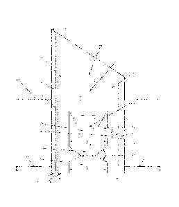
[0008] Figure 1 is a schematic, cut-away side view of an embodiment of the
flow distribution
device of the invention.
[0009] Figure 2 is a simplified schematic, perspective, side cut-away view of
the flow
distribution device of the invention in the context of a reactor vessel.
DETAILED DESCRIPTION OF THE INVENTION
[0010] The invention in one embodiment is a fluid distribution device for
distributing a
downwardly flowing poly-phase mixture including at least one gas phase and at
least one
liquid phase, above at least one catalyst bed of granular solid catalytic
material. The fluid
distribution device for receiving the liquid and gas phases has one or more
openings in the
top and/or upper portion of its height through which a gas phase can enter and
has a gas
conduit that opens to a mixing cavity within the device. The fluid
distribution device further
comprises one or more lateral openings for liquid ingress. The lateral opening
or openings
allow the liquid to enter a liquid conduit that opens to the internal mixing
cavity. The mixing
cavity allows intimate contact between the liquid and gas phases. The gas
inlet tube is
narrower than the mixing cavity, causing a venturi type effect, and creating a
lower pressure
in the interior of the fluid distribution device. The pressure differential
helps "pull- the liquid
5a
CA 02776782 2016-12-13
phase through the liquid conduit to the mixing cavity. Thus, rather than
static liquid height
on the tray, liquid flow rate through the lateral openings is at least in part
determined by the
venturi effect of the relatively narrow gas conduit. Therefore the flow
distribution device of
the invention allows greater tolerance for tray out of levelness than chimneys
of the prior art.
5b
CA 02776782 2012-04-03
WO 2011/044201 PCT/US2010/051583
The fluid (mixed gas and liquid phases) exits the fluid distribution device
via a tapered and
beveled venturi outlet as a wider spray pattern. The pressure drop across the
fluid distribution
device is minimized for energy saving and to reduce attrition on top bed
layer.
[0011] The fluid distribution device of the invention can be used in downflow
catalytic
reactors. In the downflow catalytic reactor the flow distribution device of
the invention
allows gas phase and liquid phase mixing and distributes the fluids as a well
dispersed spray
onto, for example, an underlying catalyst bed. As used herein, gas, liquid,
and combinations
thereof are referred to as "fluid" or "fluids".
[0012] The flow distribution device of the invention can be inserted into a
preexisting
chimney in a distribution tray assembly. In such a retrofit application the
flow distribution
device that can be inserted into a pre-existing chimney would thus be referred
to as a chimney
insert. In a new reactor design the flow distribution device can be installed
directly in the
distribution tray in place of a chimney. Generally, the fluid distribution
device of the
invention can range in size from about 1 inch in diameter to about 4 inches in
diameter,
although smaller or larger diameters are possible depending on the
application. In some such
embodiments, the fluid distribution device of the invention can range in size
from about 1.5
inch in diameter to about 3 inches in diameter The number of fluid
distribution devices of the
invention for use in a downflow catalytic reactor can vary and is selected
according to the
desired flow rates and other conditions desired in the downflow catalytic
reactor. The
selection process for the number of fluid distribution devices of the
invention is similar to the
conventional selection process for determining the number of standard chimneys
in a
downflow catalytic reactor.
[0013] In embodiments, the flow distribution device may be employed in a
retrofit
application. A pre-existing chimney can be used and the flow distribution
device inserted
into the existing chimney. For example, Figure 1 shows how the flow
distribution device 1
6
CA 02776782 2012-04-03
WO 2011/044201 PCT/US2010/051583
can be employed as an insert in which the diameter of the device is such that
it will insert into
a pre-existing chimney in distributor tray 85, forming an essentially fluid
tight seal with the
chimney wall 4. Figure 2 further illustrates a distribution of chimneys,
including the flow
distribution device 1, on a distributor tray. In embodiments, the fluid
distribution device
extends upwardly from the bottom of the chimney 65 to a height that is greater
than 50% or
greater than 75% of the distance between the bottom of the chimney 65 and the
top of the
chimney 70. The invention can be scaled so as to insert into a variety of
differently sized pre-
existing chimneys for retrofit application. Scaling can be accomplished by
measuring the
interior diameter of the pre-existing chimney and scaling the outer diameter
of the flow
distribution device of the invention to be smaller than the interior diameter
of the pre-existing
chimney. In embodiments, the diameter of the outer diameter of the device will
range from
about 1.5 inches to about 3 inches, although smaller or larger diameters are
not excluded and
depend on the application. In another embodiment, the invention can be
employed as a
standalone fluid distribution device.
[0014] In both retrofit and non-retrofit embodiments, the outer wall 5 forms a
cylindrical
structure. A top capping portion 6 caps the cylindrical structure formed by
the outer wall 5,
and is in fluid tight connection with the cylindrical outer wall. The top
capping portion 6
comprises at least one gas inlet opening 10. In embodiments, the gas inlet
opening ranges in
diameter from about 0.1 inches to about 1.0 inches, although smaller or larger
diameters are
not excluded and depend on the application. In some such embodiments, the gas
inlet
opening ranges in diameter from about 0.3 inches to about 0.7 inches. In an
embodiment, the
top capping portion 6 comprises a single centrally located gas inlet opening
10. The gas inlet
opening 10 opens to an axial gas conduit 15 for gas flow. The gas conduit 15
has a lower gas
conduit opening 20 that opens to a mixing cavity 25. In embodiments, the gas
conduit 15 is
coaxial with mixing cavity 25. In embodiments, the gas conduit is in a
vertical orientation.
7
CA 02776782 2012-04-03
WO 2011/044201 PCT/US2010/051583
As gas flows through the gas conduit, a pressure difference is created between
the pressure in
the mixing cavity 25 and the pressure at the gas inlet opening 10. This
pressure difference
between the lower relative pressure in the interior of the flow distribution
device and the
higher relative pressure on the exterior of the flow distribution device helps
drive liquids into
the interior of the flow distribution device through one or more lateral
openings 35. Due to
the liquid flow being at least in part due to the above described pressure
differential, any tray
out of levelness will have less of an effect on liquid flow. For example, as
long as the lateral
liquid opening or openings are below the surface of the liquid level 60, any
liquid flow
differentials caused by tray out of levelness will be minimized because the
majority of the
liquid flow is determined by the pressure differential caused by the gas flow
as opposed to
any pressure differential attributed to the varying liquid levels due to tray
out of levelness.
[0015] In embodiments, the liquid conduit 35 is positioned such that the gas
conduit
opening(s) 20 into the mixing cavity 25 is on a horizontal plane which is at
least as high (in a
vertical dimension) as the lower extent 75 of the liquid conduit 35. In some
embodiments,
the gas conduit opening 20 is on a horizontal plane between the lower extent
75 and the upper
extent 80 of the liquid conduit 35. In some embodiments, the gas conduit
opening 20 is on a
horizontal plane which is coincident with the upper extent 80 of the liquid
conduit 35. In
some embodiments the gas conduit opening 20 is on a horizontal plane no lower
than the
upper extent 80 of the liquid conduit 35.
[0016] The combination of a horizontal liquid conduit 35 and a vertical gas
conduit 20 which
is at least as high as the lower extent of the liquid conduit provides a flow
distribution device
which may be employed as a retrofit application in an existing chimney, having
an existing
side hole(s) 30 for liquid flow.
[0017] The number of lateral openings can vary depending on the desired flow
rate. The
embodiment of Figure 1 illustrates one lateral opening for liquid flow. In
other embodiments,
8
CA 02776782 2012-04-03
WO 2011/044201 PCT/US2010/051583
more than one lateral opening for liquid flow may be employed. In embodiments,
multiple
lateral openings are on the same horizontal plane with respect to each other.
In embodiments,
the lateral opening can range in diameter from about 0.2 inches to about 0.75
inches, although
smaller or larger diameters are not excluded and depend on the application. In
some such
embodiments, the lateral liquid inlet has a diameter of between 0.25 and 0.60
inches. In
embodiments, the lateral opening 30 for the liquid phase is circular and forms
the opening of
a cylindrical liquid passageway 35. In some such embodiments, the axis of the
cylindrical
liquid conduit is in a horizontal orientation. In some such embodiments, the
axis of the
lateral opening is radial to the gas conduit, i.e. is perpendicular to the gas
conduit. The
cylindrical liquid conduit 35 has a circular outlet opening 40 that opens to
the mixing cavity
25. In embodiments, the liquid flows in the liquid conduit in a direction
perpendicular to the
flow of gas in the gas conduit. In some such embodiments, at least a portion
(or all) of the
liquid flowing from the liquid conduit contacts the gas flowing from the gas
conduit in a
perpendicular direction. In general, the mixing cavity 25 has a radial
diameter B that is
greater than the radial diameter A of the cylindrical gas conduit 15, and
greater than the radial
diameter C of the liquid conduit 35. The shape of the mixing cavity can vary,
provided that
the mixing cavity has sufficient volume to allow mixing of the incoming gas
and liquid
phases prior to fluid egress. At the base of the mixing cavity 25 and below
the lateral liquid
opening 30 is a beveled and tapered poly-phase outlet nozzle 46. The poly-
phase nozzle 46
has a radial diameter D that is less than the radial diameter B of the mixing
cavity 25. In an
embodiment, nozzle inlet 45 of the poly-phase nozzle 46 is fixidly coupled to
and co-axially
aligned with the mixing cavity 25. In some such embodiments, the nozzle inlet
is co-axially
aligned with the gas conduit. The nozzle inlet 45 is centrally located at the
base of the
mixing cavity and coaxial with the cylindrical outer wall 5. The shape of the
nozzle imparts a
venturi effect to the egressing fluids by accelerating and dispersing the
liquid and gas phases
9
CA 02776782 2012-04-03
WO 2011/044201 PCT/US2010/051583
passing out of the mixing chamber. In embodiments, the bevel of the nozzle is
between 5
degrees to 85 degrees, wherein the angle of the bevel is measured from a plane
bisecting the
poly-phase nozzle 46 and parallel to the top capping portion. In some such
embodiments, the
bevel is between 30 degrees to 60 degrees, e.g. 45 degrees.
[0018] Fluids flow through the poly-phase nozzle 46 and exit the distribution
device through
a bottom opening 50 that is centrally located in the bottom wall 55. The
radial diameter E of
the bottom opening 50 is greater than the radial diameter of the most
restricted portion of the
poly-phase nozzle (D in the Figure). The fluids have a highly distributed
spray pattern upon
exiting the distribution device through the bottom opening to help ensure
uniform wetting of
an underlying catalyst bed (not shown). In an embodiment, the poly-phase
nozzle comprises
an inner wall 49. In an embodiment, the inner wall 49 is beveled. In some such
embodiments, the bevel of the inner wall is between 5 degrees to 85 degrees,
as measured
from a plane bisecting the nozzle opening. In some such embodiments, the bevel
of the inner
wall is between 30 degrees and 60 degrees, e.g. 45 degrees.
[0019] In another embodiment the inner wall can be flat. By flat it is meant
that the inner
wall is parallel to the bottom wall 55 and/or perpendicular to the side wall
S. In an
embodiment, the bottom opening has a radial diameter E that is less than the
radial diameter
F of the bottom wall. In another embodiment, the bottom opening has a radial
diameter E
that is equal to the radial diameter F of the bottom wall, i.e. the bottom
opening spans the full
basal area of the distribution device.
[0020] The flow distribution device of the invention allows greater tolerance
for tray out of
levelness than chimneys of the prior art. In addition, the flow distribution
device of the
invention can be used in retrofit applications, providing added economic
benefit and design
flexibility. Due to the design of the nozzle and diverging nozzle a spray
discharge pattern
CA 02776782 2012-04-03
WO 2011/044201 PCT/US2010/051583
that is uniform and completely wets the catalyst surface underneath the
distributor can be
achieved.
EXAMPLES
[0021] Example 1 (Comparative). Two identical chimneys, A and B, were
installed in an 11
in. diameter test cell with chimney A approximately 0.25 in. lower than
chimney B to
simulate tray out of levelness. The chimneys were approximately 6 in. apart.
The diameter
of each chimney was 2.5 in. Two lateral openings measuring 0.5 in. diameter
were present at
1.0 in. above the bottom of each of the chimneys A and B. The height of each
chimney was
6.5 in. Water with a flow rate of 2.6 gallons per minute (GPM) and air with a
flow rate of 8
standard cubic feet per minute (scfm) were used to simulate conditions in a
downflow
catalytic reactor. The water entered the chimneys through the lateral openings
and gas
entered through a top opening. The liquid flow rate was measured through each
of the
chimneys. Chimney A had a flow rate of 58.5% and chimney B had a flow rate of
41.5%.
[0022] Example 2 (invention). The experiment outlined in Example 1 was
repeated with the
flow distribution device of the invention inserted into each of the chimneys A
and B. Flow
rates were again measured through each of the chimneys. Chimney A had a flow
rate of
49.3% and chimney B had a flow rate of 50.7%.
[0023] The above examples demonstrate that the flow distribution device of the
invention
when used as a chimney insert in a retrofit type application (Example 2)
showed higher
tolerance for tray out of levelness than chimneys (Example 1) without the
insert. In addition,
the gas/liquid mixing was improved for Example 2 as compared with Example 1
and the
spray pattern for Example 2 was wider and more uniform than the spray pattern
for Example
1. Thus, the fluid distribution device of the invention demonstrated improved
characteristics
for use as a fluid distribution device when compared with a conventional
chimney.
11