Note : Les descriptions sont présentées dans la langue officielle dans laquelle elles ont été soumises.
CA 02777088 2012-05-18
FRICTIONAL NON ROCKING SEISMIC BASE ISOLATOR
FOR STRUCTURE SEISMIC PROTECTION
Inventor: Haisam Yakoub, Ottawa, Canada.
Description
General Character
This invention is related to seismic protection devices that have two main
categories. First category that
damps seismic forces transferred to a structure. Second category isolates
structures from seismic forces
and transfers fraction of seismic forces to a superstructure.
Description of the Related Art
Frictional Non Rocking Seismic Base Isolator For Structure Seismic Protection,
FNRI, is developed from an
existing art named Earthquake Protective Column Support that is invented in
1987 by Zayas Vector A.
However, search for prior arts gives the following other relevant patents:
4644714 Feb 24, 1987 06/803895 Zayas; Victor A.
62188834 Aug. 18, 1987 E04H 9/02 Shoichi
2256937 Oct.17, 1990 E04B 1/36 Hiroshi & Ikuo
US 4726161 Feb. 23, 1988 E04H 902 Nejde F. Yaghobian
6,572,071 June 3, 2003 E04H 9/02 Tsai; Chung-Shien
The main characteristics and disadvantages in the prior arts above are
summarized as follows:
1- The Earthquake Protective Column Support (EPCS) rocks like a pendulum under
seismic forces
where it has its own frequency depends on the vertical radius of the concave
base. As a result
resonance is possible in an EPCS isolated structure when EPCS period is equals
to the structure
period. Resonance results in detrimental effects on the isolated structures.
2- It generates high response displacements that result in higher costs in
manufacturing EPCS devices.
3- EPCS response forces are not low enough that it uses not low enough
friction factors due to
requirements for wind resistance during its lifecycle. If the EPCS has too low
coefficient of friction,
EPCS will rock under wind forces.
Comparatively high friction factors result in higher forces transferred to the
superstructure and
subsequently it results in higher costs to reinforce the structure against
higher seismic forces.
4- EPCS causes high stresses on the contact surfaces that causes maintenance
problems.
2/12
CA 02777088 2012-05-18
1- HASHIMOTO SHOICHI has Vibration Damping Supporter (VDS) where he claims a
device
comprising a base (3), a middle part (2) and a top part (1) and an edge (4).
The base # 3 in Vibration Damping Supporter (VDS) is a flat surface that
allows the middle part #2
to move under any horizontal force affects the isolated superstructure by VDS.
2- The most important shortcoming in the VDS is that the VDS is unstable
because the middle part is
free to rotate around its center (center of the middle part #2) that is fixed
into the upper part #1.
In engineering terms, the middle part is a roller support, that can't sustain
any horizontal force. In other
words, the structure able to move not only due to wind or earthquake forces
but also due to any
eccentricity in the construction that is inevitable in practise. As a result,
the Shoichi design is considered
unusable in its current configuration, in the FNRI inventor's opinion.
3- VDS allowable horizontal distance is too small that leads to crashing of
the base into the middle part
during an event and forcing the superstructures to vibrate or even overturning
the superstructure.
4- For very small earthquake displacements, slightly greater than '/a of the
base inner dimension, the
middle part might roll and the base slides under the middle part that will
roll over the edge and
overturn the whole system and might destroy the structure.
Tada Hiroshi and Shimoda Ikuo disclose an Oscillation Absorbing Device (OAD)
comprises many
parts. Specifically it comprises a base (5), a long rotating middle part (8
and 15) and top parts (7,10
and 17). (These numbers are shown on the drawings of Hiroshi-Ikuo patent).
1- The geometry of Oscillation Absorbing Device, OAD, doesn't sustain
horizontal forces that makes
the OAD unstable statically and subsequently unusable (similar to the VDS).
2- The OAD base is flat and holds the middle part # 8 that is able to rotate
around its center fixed into
the mass #10. This geometry- of the base and middle part is similar to that of
Shoichi VDS, where
the OAD is susceptible to rotate under any horizontal forces affect the
superstructure as well as
under earthquake horizontal forces.
In other words, the design is unstable under wind forces in its current
geometry. However, the
middle part of OAD does not roll over the base and the device will not be
overturned because the
OAD is set in an enclosed space into the ground.
3- The OAD upper mass # 10 hits the ground during an earthquake, otherwise the
whole system
including the superstructure turns over during an earthquake. In other words,
collision of the mass
#10, with the side walls of the ground, is unavoidable in order to stabilize
the system. This
collision imparts additional seismic forces into the superstructure and
reduces the efficiency of the
OAD isolation system.
3/12
CA 02777088 2012-05-18
Yaghobian claims an Earthquake Isolating Support, EIS, that has a spring (22),
friction dampers (40, 41,
42a and 42) and balls (11 and 18).
1- The Earthquake Isolating Support, EIS, has two degrees of freedoms in both
horizontal directions.
That means, it is subjected to movements due to slight winds, and slight
earthquakes. As a result
Earthquake Isolating Support (EIS) is not stable under earthquakes and will
fail during wind blow
or earthquakes.
2- There are no vertical vibrations impart horizontal movements into the
friction dampers. That
because the spring in the EIS is compressed one time under vertical weight of
structure and pushes
friction dampers outwards. Then the spring stays in that position while the
whole building rocks on
the balls. However, the vertical accelerations of earthquakes might cause
slight movements to the
spring and the friction dampers. Nonetheless, vertical displacements and
accelerations are usually
not of concern seismic protection of structures. That because vertical
accelerations are usually
much smaller and then less detrimental to structures, and because buildings
and structures
themselves withstand these additional vertical forces without any additional
reinforcements and
without any seismic protection devices. The reason for that is that material
strengths of concrete,
steel and wood and other construction materials increase about 20 % under
short term loadings
more than their normal strength under long term loadings. While horizontal
forces imparted by an
earthquake to a structure are usually few to many times greater than a
structure capacity when it is
designed only to sustain gravity and wind forces. (0.20% increase doesn't make
a difference)
3- Moreover, vertical accelerations might or might not be reduced when using a
seismic protection
device. However, that will not affect the usefulness of the seismic protection
device. Then, the EIS
friction dampers do not improve the performance of the EIS as they do not
affect response
horizontal forces and displacements of the superstructure.
4- There are no differential vertical movements produced or mitigated by the
EIS device that affect
horizontal response displacements of the device.
Shock Eliminator, SE, invented by Tsai, Chung-Shien has the following
disadvantages:
1- The inventor of Shock Eliminator, SE claims that SE withstands vertical and
horizontal vibrations
in a structure (He points out that prior arts do not address vertical
vibrations).
Fig. 3 and Fig. 4 show a similar base isolator to Zayas isolator with reversed
connection between
the slide block #31 and coupling post #21 that is fixed on the bottom of
carrier seat #20. Where the
coupling post is a convex type and slide block is concave (Zayas's isolator
has a concave at the top
and a convex in the bottom contacts a large base concave). However, the SE
above connection
serves and functions exactly similar to Zayas's device connection where both
allow rotations
around mutual centers if their contacted concaves and convex-es. Nevertheless,
springs #40, that are
4/12
CA 02777088 2012-05-18
distributed around the coupling groove to hook the bottom side of the carrier
seat to the slide block,
are too detrimental to the superstructure. That because the springs, in the
SE, work contradictory
the basic principal of the base isolators. Basic principle requires small
friction forces in order to
transfer less force that makes the isolators effective in seismic protection.
In other words the springs do make rotation of the slide block around the
coupling groove more
difficult, and thus imparting higher and avoidable additional seismic
horizontal and vertical forces
that is contradictory to the purpose of seismic base isolators.
2- The other version of the shock eliminator is illustrated in Fig. 8 and Fig.
9. This version is non
functional that because rigid connection between the slide block and the
carrier seat makes the
whole superstructure rotates around the bottom of the sliding block As a
result the superstructure
will turnover in the first few cycles of an earthquake.
Inventive Ideas in the FNRI are
= FNRI does not rock horizontally-. It moves slightly during a seismic event
due to Sliding Hammer
movements and stops immediately after ground movements stop because it is
locked after its first
return to its initial point at the lowest point of the Sliding Hammer concave.
= Resonance is not possible with structures isolated by FNRI as the Rotating
Anvil does not rock and
does not have a self period or frequency. However, Rotating Anvil returns to
lowest point of the
Sliding Hammer concave under superstructure loads and locked at that point. As
a result the
Rotating Anvil is forced to move by Sliding Hammer and it stops when Sliding
Hammer stops.
= Some of FNRI response horizontal movements are transformed to vertical
movements that reduces
the response energy transferred to horizontal displacements. Consequently,
maximum horizontal
displacements are less than maximum horizontal displacements of the other
mentioned devices such
as Earthquake Protective Column Support by Zayas.
= FNRI resists wind forces that affect superstructure during its lifecycle
that because of its Rotating
Anvil geometry that locks the Rotating Anvil and thus the superstructures at
the lowest point of the
Sliding Hammer concave.
= Contact stresses of FNRI isolator are much less than the other seismic
isolators, then maintenance
becomes less demanding.
= FNRI reduces horizontal forces by incorporating smoother surfaces between
sliding parts. This high
smoothness can be achieved by using solid lubricants that include but not
limited to Disulfides
Molybdenum, MOS2. Other lubricants may be used to have these surfaces smooth
FNRI relies on the superstructure itself to withstand seismic vertical forces,
where materials
withstand normally short term loads more than 20% than the their capacities
under static long term
loads.
5/12
CA 02777088 2012-05-18
= Although FNRI has very smooth contacted surfaces at the Rotating Anvil
bottom disk, Sliding
Hammer concave and the small concave and convex at the top of the Rotating
Anvil and Hook,
FNRI is stable in operational and non operational settings because it resists
all forces affect the
superstructure in three directions including horizontal wind forces.
= FNRI isolator is used effectively for very strong, diverse and different
frequency earthquakes, that
because there is no resonance and it produces much less response displacements
because of the
higher smoothness of its surfaces that can't be achieved in the Zayas model,
and because the
rotation of Rotating Anvil that reduces further the differential vertical
displacement and thus
horizontal displacements, then it transfers much less forces and displacements
to superstructures in
comparison with the other devices mentioned herein
System Full Description and Function
FNRI Base Isolator Function
The FNRI Base Isolator or briefly FNRI is used to isolate structures including
but not limited to
buildings, bridges, silos, factories and other structures, being made of
concrete, steel, wood or other
materials, from earthquake effects, by means of its smooth contacted surfaces
that reduces transmitted
seismic horizontal forces to superstructures and horizontal displacements
thereof.
An FNRI is installed under structure foundations or columns, one isolator
under each column or
foundation Superstructure is supported by the Hook that is the top part of the
isolator while the Sliding
Hammer, that is the bottom part, is fixed to a footing that spreads loads
carried by the isolator into ground.
Footings become sources of earthquake forces and displacements during an
event. Nevertheless, the whole
superstructure receives much smaller forces and displacements from the
isolator. That because the Rotating
Anvil receives small part of seismic forces from the Sliding Hammer, because
of smoothness of the
contacted surfaces, and transfers some of these displacements to vertical
displacements. As a result, the
Rotating Anvil reduces the maximum response horizontal displacements more than
any state of the art such
as EPOS.
There are no rigid connections between the superstructure and ground other
than the isolators in order to
ensure highest possible level of protection.
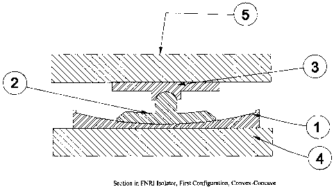
Isolator Description
Isolator parts are illustrated in Figures 1 and 2. The numbers in these
figures are as follows:
1) Sliding Hammer that is essentially a concave, number 1 in Figures 1 and 2.
6/12
CA 02777088 2012-05-18
2) Rotating Anvil that has a bottom spherical disk fixed to another top part
comprises a cylindrical neck
and a convex as in Figure 1, or cylindrical neck and concave as in Figure 2.
The cylindrical neck is
situated at the center and top of the Rotating Anvil bottom disk
3) Hook that is a disk has flat surface on the top. At bottom center of disk
there is a cylindrical neck and
concave fixed to the disk, as in Figure!, or a cylindrical neck and convex
fixed to the disk as in Figure 2.
4) Ground footing or ground.
5) Isolated Superstructure.
1. A sliding hammer is the first part,1, in Figures 1 and 2. A sliding hammer
is the bottom part that has
one flat side fixed into a ground footing that is the fourth part, 4, in
Figures I and 2, while the other upper
side of the sliding hammer is a spherical part (concave) has two radii,
vertical radius and horizontal radius.
Vertical radius is calculated from the requirements for self returning to a
stationary position at the lowest
point of the sliding hammer concave, while the horizontal radius is calculated
from the largest displacements
expected in a region for the most credible design earthquake. Horizontal
radius is slightly larger than the
largest earthquake displacement described above. The concave surface has very-
low friction coefficient.
Because the isolator design is safe for wind, friction coefficient is the
lowest possible by the industry of
lubrication so that the sliding hammer induces just smallest possible forces
to the isolated structures.
2. Rotating Anvil is a unique part in the FNRI isolator that distinguishes it
from prior arts. Rotating Anvil
comprises a thick bottom spherical disk cut from a thick spherical surface
that has an outside radius
equals to vertical radius of the Sliding Hammer concave as shown in Figures 1,
or the spherical surface
has a central part that has a radius equals to the radius of the Sliding
Hammer and the surrounding part
of the bottom disk has slightly smaller radius than Sliding Hammer to allow
tapered space that provides
for smooth rotation of the Rotating Anvil. Rotating Anvil has a top part
convex fixed onto the bottom
disk via a cylindrical neck as shown in Figure 1, or top part depressed
concave fixed onto the bottom
disk by the cylindrical neck as in Figure 2. Rotating anvil cylindrical neck
and its concave/ convex are
situated at center and top of the bottom disk In addition the top part of the
Rotation Anvil fits closely
into /around a small concave / convex that has approximately the same radius.
3. The Rotating Anvil is illustrated as the second part, # 2, in Figures 1 and
2. When one side of Sliding
Hammer moves, in the first quarter of Sliding Hammer period, towards Rotating
Anvil that is situated in
its stationary position at the lowest point of the Sliding Hammer Concave.
Sliding Hammer forces the
bottom disk of Rotating Anvil to rotate around Rotating Anvil top concave or
convex and pushing up the
whole superstructure that consumes part of imparted energy in vertical
movements and then reduces
7/12
CA 02777088 2012-05-18
horizontal displacements, where both rotations and vertical movements are
possible only if said Sliding
Hammer moves because of earthquakes.
4. When the above mentioned side of Sliding Hammer, in its second quarter of
its period, moves away from
said Rotating Anvil that moved, as mentioned above already to a higher point
of said Sliding Hammer
Concave, the Rotating Anvil slides down towards the lowest point of said
Sliding Hammer concave
because of gravity loads of the superstructure and Sliding Hammer forces the
bottom disk of said
Rotating Anvil to rotate around said Rotating Anvil top concave or convex
while it is returning back to
the lowest point of said Sliding Hammer.
5. Rotating Anvil offers two main advantages make FNRI a unique seismic
isolator. First advantage is that
it generates smaller response horizontal displacement of superstructure -a-
here parts of horizontal
displacements transferred to vertical vibrations that can be sustained by the
structure without extra
reinforcement because buildings or structures are able to sustain additional
short term vertical forces
(parallel to gravity) as it's known that material resistance increase under
short term loads. Vertical
vibrations happen because the Rotating Anvil rotates due to sliding hammer
horizontal movements
around the centre of small convex -concave joint that connects the Rotating
Anvil to the Hook of the
isolator and that does not coincide with the rotating center or the Rotating
Anvil base that coincides with
center of the Sliding Hammer concave.
6. Another very essential advantage is that the Rotating Anvil prevents the
superstructure from moving by
wind forces; no matter how smooth and slippery are the contacted surfaces of
the Sliding Hammer and
the Rotating Anvil of the isolator.
7. Hook, is the top part of the Isolator (third part, 3, in Figures 1 and 2).
This part has a bottom concave
or convex that fits around or into the Rotating Anvil top part that is a
compatible convex or concave. The top
side of the Hook is flat and fixed to a superstructure that is the fifth part,
5, in Figures 1 and 2.
The FNRI described herein protects buildings and many others structures from
earthquake forces. This
protection happens by permitting very small (unprecedented small) forces to
superstructures, thus offers
unprecedented reduction of construction, maintenance and /or rehabilitation
costs.
However, flexible connections with the main sanitary, water pipes and other
utilities are required along
with sufficient spaces around those connections and enough horizontal spaces
between retaining walls and
the isolators. Horizontal displacement are grater than the greatest design
earthquake horizontal displacement
expected in the region in order to eliminate seismic induced damages due to
collisions between isolators and
the building or structure foundations or retaining wall.
8/12