Note : Les descriptions sont présentées dans la langue officielle dans laquelle elles ont été soumises.
CA 02777165 2012-04-10
Elevator
The present invention concerns a lift having a drive unit. The
invention further concerns a wind power installation having a lift.
Nowadays lifts are usual in particular in large wind power
installations for transporting people and material. That makes it
unnecessary for example for maintenance engineers who have to perform
operations in the pod of the wind power installation to make a strenuous
and time-consuming climb by way of the ladders which generally lead
perpendicularly upwardly in the pylon. In the case of wind power
installations with hub heights of about 140 m which are not unusual
nowadays, that would more specifically involve a vertical climb up (and
naturally also a subsequent climb down) over precisely that distance of 140
m. If it is further considered that a maintenance team may be active in a
number of wind power installations in the course of a working day, it will
quickly be clear that using the ladders can involve an extreme physical
stress.
To the extent to which the size of the wind power installations is
increasing and the importance of wind power is growing, more and more
installations are being erected of a size in which a lift is at least
desirable if
not even a necessity. As a result the lifts are becoming more and more a
cost factor because they no longer occur occasionally in wind power
installations.
At this point as state of the art attention is directed generally to the
following publications: DE 10 2005 009 500 Al, WO 97/11020 Al, DE 101
04 351 Al and DE 10 2006 034 299 Al.
Therefore the object of the present invention is to reduce the costs of
the lift and thus make the lift economically more attractive.
For that purpose the lift of the kind set forth in the opening part of
this specification is characterised by a cupboard which is used as a lift car.
In that respect the invention is based on the realisation that a
cupboard or cabinet in its basic structure with a bottom, side walls and a
CA 02777165 2012-04-10
2
door does not differ from a lift car produced specifically for a lift.
Naturally
there are differences, for example in the suspension and operation of the
door, but those differences can be removed, insofar as they are an obstacle
to use of a cupboard as a lift car, so that the complication and expenditure
overall is always still less than the complication and expenditure on a lift
car constructed specifically for the lift.
To permit the lift to be transported to its location of use in a space-
saving fashion, provided at the top side of the lift car at opposite sides are
substantially horizontally arranged holders and carriers arranged extending
substantially vertically thereon for the drive unit, wherein the carriers are
releasably connected to the holders and are vertically displaceable. In that
way the drive unit can be pushed into the lift car for transport so that, for
transport purposes, only the outside dimensions of the lift car are relevant
and the drive unit does not require any additional space for transport
thereof.
For that purpose in the first position the connection is made between
the drive unit and the lift car in the operating position so that all of the
internal space in the lift car is available for transporting freight and/or
people while in the second vertically displaced position the drive unit is
held
in a lowered position in the lift car, which saves on transport space.
The change between the transport position and the operating
position only involves releasing the connection between the drive unit and
the lift car, moving the drive unit into the desired position and restoring or
tightening the connection in the correspondingly different position. There is
no need for further interventions. In that way the change between the
transport position and the operating position can be effected very easily
and with a time saving.
In a preferred development of the invention the lift system is
characterised by a drive unit having a capstan winch. That means that
there is no need for a complicated and expensive rail arrangement within
the pylon.but it is only necessary to provide two appropriately sized cables.
One for normal operation and one as a catch cable to be able to stop the lift
in the event of a technical failure.
CA 02777165 2012-04-10
3
Particularly preferably the entire control is arranged in the drive unit
and an operating element connected to the control extends down into the
lift car so that a change in the drive unit between the transport position and
the operating position is possible without any intervention into the control
and/or the operating element connected thereto.
A further possible way of cost savings is afforded if, instead of a
particular lift car, a cupboard which is usually employed as a switch cabinet
is used as the car for a lift. Switch cabinets can be produced in large
numbers at lower cost, they can be used as cars for lifts and they can be
easily adapted to the particular demands involved as a car for a lift so that
the cost advantage is also not lost as a result of that.
Particularly advantageously the lift according to the invention is used
in a wind power installation as there, apart from erection, the lift is only
used occasionally and therefore has to meet the fundamental demands
made on a lift, but particular comfort is not required.
A conventional wind power installation which can be equipped with a
lift according to the invention includes at any event a foundation or another
base on which a pylon, in particular a tubular steel or concrete pylon, is set
up, at the upper end of which is arranged a wind power installation pod.
Fixed to the pod is an aerodynamic rotor which is to be caused to rotate by
means of wind and which for that purpose has at least one and usually
three rotor blades. The pod further includes some elements for operation of
the wind power installation, which can usually include the generator
coupled to the aerodynamic rotor, as well as various other elements such
as a drive unit for rotating the pod to change the azimuth position thereof,
or for example aviation lights to make the pod better visible to air traffic,
to
give just some examples. The lift according to the invention is to be
provided in particular in the pylon in order to convey one or more people
and/or articles from the base of the pylon to the pod, and/or vice versa.
The invention is described in greater detail hereinafter with reference
to the Figures in which:
Figure 1 shows an overall perspective view of a lift according to the
invention,
CA 02777165 2012-04-10
4
Figure 2 shows a switch cabinet body,
Figure 3 shows the switch cabinet body with door and side portions,
Figure 4 shows a switch cabinet body as shown in Figure 3 and in
addition a drive unit,
Figure 5 shows a switch cabinet body as shown in Figure 4 but with
the drive unit lowered into the lift car,
Figure 6 shows a simplified view of the operating portion in the
interior of the lift car,
Figure 7 shows a simplified view of the operating portion on the
outside on the lift car, and
Figure 8 shows a view of the control cabinet from the side towards
the interior of the lift car.
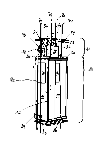
Figure 1 shows the complete lift with the lift car 10 and the drive unit
11. The lift car 10 substantially includes a switch cabinet body 12 as a load-
bearing structure. Fitted into that switch cabinet body 12 is a sliding door
14 in which a window 16 is in turn provided. Side portions and naturally a
rear wall (not shown in this Figure) are also installed. The side portion 18
having a window 20 can be clearly seen in this Figure.
In addition, shown at the left-hand side which is visible in this Figure
are guide cable rollers 22 for the guide cable 74 and a carrier cable guide
24 through which the carrier cable 70 is guided. Corresponding guide cable
rollers are disposed on the opposite side of the lift car 10 according to the
invention, that side however is not shown in this Figure. There, there is
also a catch cable guide (also not shown in this Figure) for the catch cable
72 which holds the lift car for example upon failure of the normal lift drive.
Holders 30 are mounted at the top side of the switch cabinet body 12
and carriers 32 which extend perpendicularly upwardly are in turn attached
to the holders 30. Disposed on the carriers 32 is a roof plate 34 which
protects the lift from articles which drop down. Also mounted to the holders
32 is a capstan winch 36, by means of which the lift can travel upwards or
downwards in the desired direction on the carrier cable 70. There is also a
control cabinet 38 in which the entire control system is disposed. This
Figure also shows a catch device 50 which as a safety device holds the lift
CA 02777165 2012-04-10
on a catch cable 72 if the drive consisting of the capstan winch 36 and the
carrier cable 70 should fail. In addition to the carrier cable 70 and the
catch
cable 72 there are also guide cables 74 which guide the lift so as to avoid
swinging movement of the lift.
5 Provided for the power supply is a cable 92 which is passed into the
drive unit by way of a cable guide 90. Finally the Figure shows a bottom or
floor switch 80 which detects when the lift encounters the floor (or another
obstacle) and which can stop the lift.
Figure 2 shows a perspective view of a switch cabinet body 12 which
according to the invention forms the load-bearing structure of the lift car
10. Such a switch cabinet body 12 is nowadays a component which is
produced in large numbers and which therefore is relatively inexpensive but
which enjoys sufficient strength and load-bearing capability to be able to
provide for transporting people and material.
Figure 3 shows that switch cabinet body 12 with an installed sliding
door 14 in which there is a window 16. This Figure further shows a side
portion 18 having a further window 20 while illustrated in the lower region
of the side portion 18 are guide cable rollers 22 and a carrier cable guide
24.
It can be clearly seen in this Figure that by relatively simple
measures, the switch cabinet body 12 can be made into a car for a lift,
which meets all requirements, but which overall is markedly less expensive
than a standard lift car.
In Figure 4 the view in Figure 3 has been supplemented by holders
30 which are fixed at the top on the switch cabinet body 12. Carriers 32 are
in turn mounted perpendicularly to the holders 30. A roof plate 34 is fitted
on the carriers 32. The roof plate 34 prevents articles being able to drop
from above into the lift car or the drive. Arranged on the carriers is a
capstan winch 36, a control cabinet 38 and a catch device 50, by means of
which the essential functions of the lift can be performed. There are also
guide cable rollers 22 which guide the lift during operation along guide
cables which are provided, and which thus prevent the lift from swinging.
Shown at the underside of the lift car 10 is a floor switch 80 which detects
CA 02777165 2012-04-10
6
when the lift encounters the floor or meets an obstacle and can
immediately stop the lift.
The carriers 32 are releasably connected to the holders 30 and can
be displaced in the direction of the vertical axis of the lift. In that way
the
drive unit carried by the carriers 32 can be lowered into the lift car 10 so
that the lift requires less room for transport, namely essentially the space
in the lift car 10.
That is shown in Figure 5. The roof plate 34 can be seen in Figure 5
above the holders 30 while the remainder of the drive unit is lowered with
the carriers 32 (not shown in this Figure) into the lift car 10.
In addition this perspective view shows the right-hand side of the lift
with a right-hand side wall 19 and a right-hand side wall window 21, as
well as an external operating portion 60 shown on the right-hand side wall
19 and guide cable rollers 26 and a catch cable guide 28.
To be able to operate the lift at least one operating unit is naturally
required. Figure 6 shows such an operating unit 62 which is provided in the
interior of the lift car and which besides operating buttons for moving
upwards or downwards includes a switch for switching on the control
system, a reset button, an emergency stop switch and an operation/fault
light. In that way the essential lift functions can be controlled and
operational readiness or a fault can be signalled.
Figure 7 shows an external operating portion 60 by way of which the
fundamental functions can be operated, for example when transporting
material. That external operating portion 60 is used when people transport
is not involved. Then the lift which is filled with material can be set in
operation for example with the 'up' button in order to transport the
material upwardly from the base of the installation. The 'down' button
causes automatic travel in the opposite direction, that is to say
downwardly.
Figure 8 shows the side 40 of the control cabinet 38 which is towards
the interior of the lift car. Provided at that side of the control cabinet 38
is a
multiplicity of lights and switches which signal different operating states or
which make it possible to actuate given functions. In normal operation the
CA 02777165 2012-04-10
7
lift is operated by way of the operating portion 60 or the operating portion
62. As soon as a fault is displayed at one of those operating portions
however, the operator can obtain further information about the nature of
the fault, with a glance upwardly, namely to the underside 40 of the control
cabinet 38, which is shown in Figure 8.
The switch labelled 'lighting' serves for switching the lighting on and
off.
The light identified by 'control voltage 24 V ok' shows whether the 24
V voltage required for satisfactory operation of the control is available and
the lift can be operated.
The light 'fault rotary field' shows whether the rotary field at the
motor for the desired operation is or is not in order. A light which is
switched on indicates a fault. That can be for example a missing phase in
the power supply or a wrong connection of the rotary field.
The 'door open' light shows precisely that, namely that the door of
the lift is not correctly closed. If the door is correctly closed that display
can
also indicate a defective door switch. More specifically, both mean that the
lift cannot be set in operation. That ensures that the lift moves only when
the door is securely and correctly closed.
The 'limit switch down' light shows triggering of the lower limit switch
(the so-called car floor switch), for example when the lowermost position is
reached or the switch is actuated by an obstacle. Triggering of the upper
limit switch or the emergency stop function is signalled by the 'limit switch
up/emergency stop' light. Continuous lighting thereof shows that the lift
has reached the upper operating position while flashing shows the
uppermost emergency stop position.
The 'overload' light indicates overloading of the lift and the 'catch
device triggered' light indicates that the catch device has fixed the lift on
the catch cable so that further movement of the lift is not possible without
releasing the catch device.
As human lives also depend on reliable functioning of the drive and
the safety devices, a maintenance interval is prescribed, within which those
components have to be repetitively checked. In the present example this
CA 02777165 2012-04-10
8
involves a 200 hour interval. A display light is also provided for that
purpose to indicate the expiry of that interval to the user. That light is
labelled '200 h maintenance'.
Finally there is a 'bridging limit switch down' switch which permits
bridging of the limit switch and thus enables that switch to be taken out of
operation, if that is required for example upon installation for re-starting
the arrangement or also when changing the cables.