Note : Les descriptions sont présentées dans la langue officielle dans laquelle elles ont été soumises.
CA 02779447 2012-04-30
WO 2011/062649 PCT/US2010/003046
-. 1 -
COAXIAL TUBE SOLAR HEATER WITH NIGHTTIME COOLING
Technical Field
This disclosure relates generally to solar water-heating-
systems,. and more specifically to an improved coaxial tube
solar water-heating-and-cooling-system capable of providing
reliable heating, and, when warranted, cooling.
Background Art
United States Patent no.. 6,014,968 entitled "Tubular
Heating-Pipe Solar Water-Heating-System With Integral Tank"
that issued January 18, 2000, on a=patent application filed in
the name of Siang Teik Teoh ("the '968 patent") discloses a
solar water-heating system having collector core that includes
a plurality of hollow heating-pipes. Each heating-pipe has a
longitudinal axis and an interior. that is surrounded by an
outer wall. When assembled into the collector core of the
solar water-heating system, the. heating-pipes are aligned
substantially parallel to each other, and in use are adapted
to be inclined to the horizontal. Thus, when in use each of
the heating-pipes has an open upper end that is elevated above
the heating-pipe's closed lower end. The open upper end of the
heating-pipes disclosed in the '968 patent extend directly to,
open into, and communicate directly with:
1. a lower level of a hot-water storage-tank; or
2. a lower portion of another the solar water-heating-
panel.
Each of the hollow heating-pipes has an outer wall that
surrounds a hollow cooler-water -return-pipe. The cooler-water
return-pipe within each of the heating-pipes has an internal
cross-sectional area that is approximately equal to one-third
(1/3) to one-half (1/2) of an internal cross-sectional area
enclosed by the surrounding heating-pipe's outer wall. The
cooler-water return-pipe within each of the heating-pipes also
has a length that is slightly longer than a length of the outer
wall of the heating-pipe. Thus, the open upper end of the
cooler-water return-pipe extends'beyond the open upper end of
the heating-pipe's outer wall. In this way the upper end of
CA 02779447 2012-04-30
WO 2011/062649 PCT/US2010/003046
- 2 -
the cooler-water return-pipe extends into and communicates
directly with:
1. the lower level of a hot-water storage-tank; or
2. the lower portion of another the solar water-heat-
ing-panel.
A lower end of each.cooler-water return-pipe is perforated so
fluid may flow outward from within the lower end of each
cooler-water return-pipe toward. the surrounding outer wall of
the heating-pipe.
Preferably, the solar water-heating system disclosed in
the '968 patent includes a transparent cover, usually made of
glass, that is disposed immediately adjacent to and shields the
heating-pipes. The solar water-heating-system disclosed in the
'968 patent when assembled with evacuated glass thermosyphon
coaxial heating tubes exhibits the highest thermal efficiencies
of all presently known solar water-heating systems.
Existing solar hot water panels are susceptible to
mechanical damage if water in the heating-pipes freezes and
cracks the heating-pipes. Prior systems have addressed this
problem through an indirect system in which solar radiation
heats an antifreeze solution in heating-pipes, or is heated at
a condenser portion of heat pipes. The hot antifreeze solution
then circulates through a heat exchanger located in the hot-
water storage-tank to heat the'=water. This type of solar
water-heating-system is inefficient since. the water is only
indirectly heated by the antifreeze solution. Consequently,
this indirect solar water-heating-panel system heats less water
than a direct solar water-heating-system in which the water
being heated circulates through' heating-pipes. Moreover,
indirect solar water-heating panel systems are more expensive
and complicated than direct solar water-heating-systems, and
require maintenance including regular topping up of any
intermediate -working=liquid antifreeze solution if such is
used.
Another problem sometimes experienced with prior water
filled solar hot water panels occurs if the hot-water storage-
tank's and heating-pipes'. water supply is accidentally
interrupted for a few weeks.' During the water supply interrup-
CA 02779447 2012-04-30
WO 2011/062649 PCT/US2010/003046
- 3 -
tion the hot-water storage-tank and heating-pipes can boil dry.
After the hot-water storage-tank and heating-pipes boil dry,
restoring the water supply to the solar hot water panel on a
hot day introduces cold water swiftly into hot heating-pipes.
Swift introduction of cold water into hot heating-pipes can
cause the heating-pipes to bend to such an extent that they cam
shatter either:
1. a glass tube of an evacuated thermosyphon coaxial
heating tube that surrounds the solar hot water
panel's outer wall and'hollow cooler-water return-
pipe; or
2. an immediately adjacent transparent glass cover.
Disclosure
The present disclosure provides a very high efficiency
collector array panel for an improved solar water-heating-and-
cooling-system. The'very high efficiency collector array panel
includes coaxial heating tubes that are similar to those
disclosed:
1. in United States 'Statutory Invention Registration
US H2231 H entitled '!Tubular Heating-Pipe Solar
Water-Heating-System With Integral Tank" that was
published on August 4, 2009, on an application filed
in the name of Siang Teik Tech ("the H2231 SIR"),
and also
2. in the '968 patent.
However, the solar water-heating-and-cooling-system disclosed
herein offers enhanced resistance to thermal shock damage that
may result from unintentionally, introducing cold water or cold
heating fluid into empty, hot heating tubes on a sunny day
where the heating :tubes have remained exposed to solar
radiation prior to filling.
An object of the present disclosure is to provide an
efficient solar water-heating-and-cooling-system.
Yet another object of the present disclosure is to provide
a highly efficient coaxial heating tube solar water-heating-
and-cooling-system that exhibits enhanced resistance to thermal
shock damage.
CA 02779447 2012-04-30
WO 2011/062649 PCT/US2010/003046
4 -
Yet another object of the' present disclosure is to provide
a solar water-heating-and-cooling-system that advantageously
captures nighttime radiative cooling capability of coaxial
solar heating tube collectors that present conventional solar
water-heating-systems fail to utilize.
Yet another object of the present disclosure is to provide
a solar water-heating-and-cooling-system that is simpler and
easier to install.
Yet another object of the present disclosure is to provide
a solar water-heating-and-cooling-system that less architectur-
ally intrusive.
Yet another object of the present disclosure is to provide
a solar water-heating-and-cooling-system that is less visible.
Briefly, in one aspect this disclosure includes a solar
heating system that has at. least one collector array panel.
The collector array panel is adapted for being located on a
sloping roof of a -building, ' and includes a plurality of
thermosyphon heating tubes. The solar heating system also
includes a liquid source adapted for supplying liquid to the
collector array panel's heating tubes. Finally, the solar
heating system includes a cut-off valve coupled both to:
1. a mains supply for receiving liquid therefrom; and
2. the liquid.source.
Configured in this way, the cut-off valve automatically blocks
liquid received by the cut-off valve from the mains supply from
filling the collector array panel ',s heating tubes whenever such
filling could damage the collector array panel.
In another aspect this disclosure includes a solar heating
system that has at least one collector array panel. The
collector array panel is adapted. for being located on a sloping
roof of a building, and includesa plurality of thermosyphon
heating tubes, each heating tubes being open at a lower end
thereof. The solar heating system also includes an intermedi-
ate manifold coupled to lower, ends of the collector array
panel's heating tubes for supplying liquid thereto. The solar
heating system further includes a liquid source adapted for
supplying liquid via the intermediate manifold to lower ends
of the collector array panel's heating tubes. Finally, the
CA 02779447 2012-04-30
WO 2011/062649 PCT/US2010/003046
-
solar heating system includes a pressure reducing valve that
is:
1. coupled between a- mains supply and the liquid
source; and
5 2. set at a low pressure and flow rate.
Configured in this way the pressure reducing valve limits a
rate at which the collector array panel.'s heating tubes slowly
fill with liquid thereby preventing filling of the heating
tubes from damaging the collector array panel.
In yet another aspect this disclosure includes a solar
heating-and-cooling system that has at least one collector
array panel. The collector array panel is adapted for being
located on a sloping roof of. a building, and includes a
plurality of thermosyphon heating/cooling tubes. Each
heating/cooling tube is open both:
1. at an upped' end of the collector array panel; and
2. at a lower end thereof.'
The disclosed solar heating-and-cooling system also includes
a heated-liquid chamber that is located above the collector
array panel's upper end. The heated-liquid chamber is coupled
to the collector array panel.'s heating tubes for receiving hot
liquid warmed within the collector array panel. Finally, the
solar heating-and-cooling system includes a cold liquid storage
tank that is located below the collector array panel's lower
end. The cold liquid storage tank is coupled to the collector
array panel's heating/cooling tubes for receiving cool liquid
chilled within the collector array panel.
In yet another aspect this disclosure includes a solar
cooling system that has at least one collector array panel
adapted for being located on a'sloping roof of a building. The
collector array panel includes a plurality of thermosyphon
cooling tubes each 'of which is open at a lower end of the
collector array panel. Finally, the solar cooling system
includes a cold liquid storage tank located below the collector
array panel's lower end. The cold liquid storage tank is
coupled to the collector array panel's cooling tubes for
receiving cool liquid chilled within the collector array panel.
CA 02779447 2012-04-30
WO 2011/062649 PCT/US2010/003046
6
In a final aspect this disclosure includes a solar heating
system that has at least one collector array panel adapted for
being located on a sloping roof of a building. The collector
array panel includes a plurality 'of thermosyphon heating tubes,
each heating tube being open at an upper end of the collector
array panel. The collector array panel also includes an upper
manifold located at the collector array panel's upper end that
exchanges liquid with the collector array panel's heating
tubes. The solar heating system further includes a
heated-liquid chamber located above the collector array panel's
upper end that receives hot liquid warmed within the collector
array panel. Finally, the solar heating system includes a
heated-liquid coaxial tube that conducts liquid, via the upper
manifold, between collector array panel's heating tubes and the
heated-liquid chamber.
These and other features, objects and advantages will be
understood or apparent to those of ordinary skill in the art
from the following detailed description of the preferred
embodiment as illustrated in the various drawing figures.
Brief Description of'Drawings
FIG. 1A is a partially cut, away perspective view of a
solar water-heating-and-cooling-system including a collector
array panel, the solar . water-heating.-and-cooling-system
providing both heating and cooling in accordance with the
present disclosure.
FIG. 1B is a partially cut away perspective view of a hot
water storage tank and a portion of a collector array panel
resting on a roof of a house taken along the line 1B-1B in FIG.
1A.
FIG. 2 is a diagram illustrating arrangement of FIGs.
2A - 2E into a cross-sectional plevational view of the entire
solar water-heating-and-cooling-system depicted in FIG. 1A when
heating water during daytime.
FIG. 2A is a cross-sectional 'elevational view of a hot
water storage tank included in the solar water-heating-and-
cooling-system depicted in FIG. 1A when heating water during
daytime.
CA 02779447 2012-04-30
WO 2011/062649 PCT/US2010/003046
7 .
FIG. 2B is a cross-sectional elevational view of a glazed
collector array panel included in, the solar water-heating-and-
cooling-system depicted in FIG. LA when heating water during
daytime.
FIG. 2C is a cross-sectional elevational view of an
intermediate manifold included in the solar water-heating-and-
cooling-system's collector array panel depicted in FIG. 1A when
heating water during daytime..
FIG. 2D is a cross-sectional elevational view of a cold
water storage tank included in the solar water-heating-and-
cooling-system depicted in FIG. lA when heating water during
daytime.
FIG. 2E is a cross-sectional elevational view of a cooling
radiator included in the solar water-heating-and-cooling-system
depicted in FIG. 1A when heating water during daytime, and a
support frame therefor.
FIG. 3 is a diagram illustrating arrangement of FIGs.
3A - 3E into a cross-sectional elevational view of the entire
solar water-heating-and-cooling-system depicted in FIG. 1A when
cooling water during nighttime.
FIG. 3A is a cross-sectional elevational view of the hot
water storage tank included in the solar water-heating-and-
cooling-system depicted in FIG: 1A when cooling water during
nighttime.
FIG. 3B is a cross-sectional elevational view of the
glazed collector included in the solar water-heating-and-
cooling-system depicted in FIG. lA when cooling water during
nighttime.
FIG. 3C is a cross-sectional elevational view of the
intermediate manifold included in the solar water-heating-and-
cooling-system's collector array panel depicted in FIG. lA when
cooling water during,nighttime.
FIG. 3D is a cross-sectional elevational view of the cold
water storage tank included in the solar water-heating-and-
cooling-system depicted in FIG; lA when cooling water during
nighttime.
FIG. 3E is a cross-sectional elevational view of the
cooling radiator included in the solar water-heating-and-
CA 02779447 2012-04-30
WO 2011/062649 PCT/US2010/003046
-.8 -
cooling-system depicted in FIG. 1A when cooling water during
nighttime, and the support frame therefor.
FIG. 4A is a cross-sectional elevational view of the hot
water storage tank included in- the solar water-heating-and-
cooling-system taken along the line 4-4 in FIG. 1A when filled
with water.
FIG. 4B is a cross-sectional elevational view of the hot
water storage tank included in the solar water-heating-and-
cooling-system taken along the line 4-4 in FIG. 1A if the solar
water-heating-and-cooling-system has' boiled dry.
FIG. 5 is a cross-sectional elevational view of the glazed
collector array panel included in the solar water-heating-and-
cooling-system taken along the line 5-5 in FIG. lA.
FIG. 6 is a cross-sectional elevational view of the
intermediate manifold included in the solar water-heating-and-
cooling-system's collector array panel taken along the line 6-6
in FIG. 1A.
FIG. 7 is a cross-sectional elevational view of the
unglazed collector array panel included in the solar water-
heating-and-cooling-system taken along the line 7-7 in FIG. 1A.
FIG. 8 is a partially* cut away perspective view of the
intermediate manifold when operating to heat water during
daytime that is included in *the solar water-heating-and-
cooling-system's collector array panel of FIG. 1A.
FIG. 9 is a partially cut away perspective view of the
intermediate manifold when operating to cool water during
nighttime that is included. in, the solar. water-heating-and-
cooling-system's collector array panel of FIG. lA.
FIG. 10 is a partially cut 'away perspective view of an
alternative embodiment of the intermediate manifold that has
enlarged diameter pipes when, operating to heat water during
daytime that may be included in' the solar water-heating-and-
cooling-system's collector array panel of FIG. 1A replacing the
intermediate manifold depicted in FIGs. 8 and 9.
FIG. 11 is a partially cut away perspective view of an
alternative embodiment a solar water-heating-and-cooling-system
including a single -connection collector array panel, the solar
CA 02779447 2012-04-30
WO 2011/062649 PCT/US2010/003046
- 9 -
water-heating-and-cooling-system in accordance with the present
disclosure providing'both heating and cooling.
FIG. 12 is a partially cut away perspective view of an
upper manifold included in the single connection collector
array panel depicted in FIG. 11' during daytime heating.
FIG. 13 is a perspective view of an alternative embodiment
solar water-heating-and-cooling-system including a single
connection collector array panel, the. solar water-heating-and-
cooling-system in accordance 'with the present disclosure
providing only heating.
FIG. 14 is a partially cut. away perspective view of a
hinged-opening lower tube holder, that receives lower ends of
heating/cooling tubes included- in the collector array panel
depicted in FIG. 13 when used only for heating.
FIG. 15 is a plan cross-sectional view of the hinged-
opening lower tube holder that receives lower ends of heat-
ing/cooling tubes included .in the collector array panel
depicted in FIG. 13 indicating movement of a bottom tube holder
responsive to the heating/cooling tubes' expansion and contrac-
tion when used only for heating.
FIG. 16 is a cut-away cross.-sectional view of yet another
alternative embodiment solar, water-heating-and-cooling-system
that includes a pair of glazed collector array panels each of
which rests on a different roof, .surface that abut each other
at a ridge of the roof located beneath the hot water storage
tank and are connected in parallel to-the cold water storage
tank.
Best Mode for Carrying Out the Disclosure
Drawing FIGs. 1A-10 included in this patent application,
in conjunction with the disclosure respectively of the '968
patent and of the H2231 -SIR, provide sufficient detail
information to permit. assembling and using various solar water-
heating-and-cooling systems disclosed herein. The '968 patent
and the H2231 SIR are' both hereby incorporated by reference as
though fully set forth here.
If a solar water-heating system of the type disclosed in
the '968 patent and the H2231 SIR having evacuated glass
CA 02779447 2012-04-30
WO 2011/062649 PCT/US2010/003046
-
`thermosyphon coaxial heating tubes ' experiences dry stagnation,
temperature inside evacuated thermosyphon.coaxial heating.t.ube
can. se to 250 .C. :When such hot, empty evacuatedthermosyphon
coaxial heating tubes fill from the top down. ,,as `.generally
..'5 occurs the speed of liquid flowing down through;.hot.;.heat:ing
pubes cannot,be::controlled because gravit y dr vese cold
(liquid 1:6. downward- trickle flow. If such a solar water-heating
system is empty and thermosyphon'coaxial heating tubes remain
exposed to solar radiation for one or two hours on a hot sunny
10 day, upon filling the coaxial heating tubes with cold water or
heating liquid from the top the tubes exhibit slight temporary
arcing or bending. Arcing or bending occurs because the cold
liquid trickling down'the hot heating tubes causes.each heating
tube's lower half cross-section to contract suddenly while the
upper. half cross-section remains dry and hot and therefore
Uncontracted. Such sudden uneven contraction across the. tube -I..s
cross-section urges the heating tubes to arc upwards slightly
and in.extreme cases to contact and even shatter an adjacent
transparent glass cover or a surrounding evacuated glass tube.
The H2231 SIR addresses this problem by utilizing corrugated
heating tubes which are more flexible and thus less prone to
exert any strong force on the enclosing glass tube or glass
cover. if the inner corrugated tube were .to arcs slightly.
However, to avoid damage even corrugated heating tubes that
exhibit lesser arcing still must be spaced further away from
the glass tube or glass cover. 'Spacing corrugated heating
tubes further away from the glass cover restricts. heating tube
diameter. The solar water-heating-and-cooling system disclosed
herein avoids the extreme heating tube bending caused by the
cold water or heating liquid trickling down the hot heating
tube by filling tubes through a manifold or tank located below
the tubes, and not from above as disclosed in the '968 patent
and in the H2231 SIR.
Some flat plate tube and fin solar thermosyphon solar
water-heating systems such as that disclosed in United States
Patent no. 4,084,578. entitled "Solar Water Heater of Natural
Circulation Type,!' that issued' April 18, 1978, on a patent
application filed in the name of Toshihiro Ishibashi ("the '578
CA 02779447 2012-04-30
WO 2011/062649 PCT/US2010/003046
11 ,-
patent"), also disclose filling the collector from below.
However, thermosyphon solar water-heating systems of the type
depicted in the 1578 patent are less thermally efficient in
comparison with a system having evacuated glass coaxial heating
tubes.when used.in the solar water-heating systems disclosed
both in the 1968-patent and in the H2231 SIR. Consequently,
under dry stagnation thermosyphon solar water-heating systems
such as that disclosed in the '578 patent do nor reach as high
a temperature as that exhibited by collector array panels
having evacuated glass coaxial'heating tubes. Avoiding the
extreme bending of evacuated thermosyphon coaxial heating tubes
during cold fill on a hot day by.controlling the rate of cold
liquid inflow upward into the collector array panel's coaxial
heating tubes as disclosed herein permits safely locating the
solar water-heating-and-cooling system's coaxial thermosyphon
heating tubes closer to the glass tube or glass cover thereby
increasing solar collection efficiency.
Furthermore, the solar water-heating-and-cooling system
disclosed herein preferably also'preheats infilling liquid by:
1. first passing it through a heat-exchange-coil
located in a hot water storage tank; and
2. then initially filling coaxial thermosyphon heating
tubes of a.lower, unglazed collector array panel;
before liquid rises slowly into the coaxial thermosyphon
heating tubes of an upper, glazed collector array panel.
Filling the coaxial thermosyphon heating tubes of the upper,
glazed collector array panel in this way reduces temperature
difference between liquid and hot coaxial thermosyphon heating
tubes of the upper, glazed collector array panel.
Moreover, the solar water-heating-and-cooling system
disclosed herein may advantageously include a pressure reducing
valve set to very low pressures of 5 psi or less and a flow
control valve, both of which connect in series along a cold
water or liquid supply pipe. Including such a pressure
reducing valve and flow control'.valve regulates the flow rate
of water or liquid filling the collector array panel's coaxial
thermosyphon heating tubes so-the liquid's level rises slowly
CA 02779447 2012-04-30
WO 2011/062649 PCT/US2010/003046
12.
in the glazed heating tubes thereby avoiding sudden extreme
arcing or buckling of the heating tubes.
The slow infill flow rate does 'not affect the flow rate
or pressure of hot water drawn off to hot showers or for other
uses because hot water is drawn from the solar water-heating-
and-cooling system disclosed herein through a pressurized heat-
exchange-coil, depicted inFIGs.= 2A, 3A 4A and 4B, that is
immersed in the hot water storage tank. Thus, the flow rate
or pressure of hot water drawn off for hot showers or other use
is from the mains water supply or household water pump, and
therefore the hot water pressure. can be set to any desired
value.
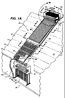
FIG. 1A depicts an overall view of the solar water-
heating-and-cooling system referred to by the general reference
designation 20. Specifically, FIG. lA illustrates a portion
of the solar water-heating-and-cooling system 20 installed over
roof tiles 22 of a sloping roof 24 of a single story building
26. Included in the solar water-heating-and-cooling system 20
depicted in FIG. lA are:
1. an optional unglazed collector array panel 32;
2. a thermally insulated intermediate manifold 34; and
3. a glazed collector array panel 36 of the solar
water-heating-and-cooling system 20.
A thermally insulated hot-water storage-tank 38 of the solar
water-heating-and-cooling system 20 rests on a ridge 42 of the
roof 24 as better illustrated in FIG. 2. A cold water storage
tank 46 and a cold radiator array 48 of the solar
water-heating-and-cooling system 20 are located below the roof
24 inside the building 26. For the solar
water-heating-and-cooling system 20 depicted in FIGs. lA, 1B
and 2, thermosyphon coaxial heating tubes included in the
unglazed and glazed collector array panels 32, 36 respectively
extend directly into the hot-water storage-tank 38, the
intermediate manifold 34, and the cold water storage tank 46.
Resting on the sloping roof 24, hoter liquid in the thermo-
syphon coaxial heating tubes of the unglazed and glazed
collector array panels 32, '36 =rises toward the hot-water
storage-tank 38, and cooler liquid in the hot-water
CA 02779447 2012-04-30
WO 2011/062649 PCT/US2010/003046
13
storage-tank 38 descends through the thermosyphon coaxial
heating tubes towards the bottom of the unglazed and glazed
collector array panels 32, 36..
FIGs. 5-7 provide differing cross-sectional views of
thermosyphon coaxial heating/cooling tubes 52 included in the
unglazed collector array panel 32 and glazed collector array
panel 36. In the illustration of FIG. 5, evacuated glass tubes
54 of the glazed collector array panel 36 enclose preferably
corrugated outer heating/cooling tubes 56 that in turn enclose
inner heating/cooling tubes 58.,'For the unglazed and glazed
collector array panels 32, 36 included in the solar
water-heating-and-cooling system 20 depicted in FIGs. 1A, 2 and
2B through 2C, the outer and inner tubes 56, 58 are open both
at the upper end of the unglazed and glazed collector array
panels 32, 36 and at the lower end thereof. All that appears
in FIG. 6's cross-sectional view=of the intermediate manifold
34 are ends of the outer and inner tubes 56, 58 that are
included in the glazed collector array panel 36. Similarly,
FIG. 7's view of the, unglazed collector array panel 32, that
lacks the glass tubes 54, depicts only cross-sections of the
outer and inner tubes 56, 58. Also depicted in FIGs. 5 and 7
is a highly reflective surface 62, such as reflective aluminum
foil or other reflective metal sheet, that is corrugated so
each of the thermosyphon coaxial heating/cooling tubes 52 lies
at a corrugation's focus.
The illustration of FIG.. 5 also depicts an optional
transparent protective cover 63, preferably made from a sheet
of acrylic material such as.* Peispex or from a sheet of
tempered glass, that spans across lateral edges.of the glazed
collector array panel 36. above the thermosyphon coaxial
heating/cooling tubes 52. Adding' the'transparent protective
cover 63 to the glazed collector. array panel 36 increases its
resistance to hail damage. Alternatively, while exhibiting'a
lesser thermal performance than a glazed collector array panel
36 having vacuum glass tubes 54, a less expensive glazed
collector array panel 36 can be assembled by omitting the
vacuum glass tubes 54 and including the. transparent protective
cover 63.
CA 02779447 2012-04-30
WO 2011/062649 PCT/US2010/003046
14 -
The cross-sectional views of FIGs. 2 and 2A-2E illustrate
the solar water-heating-and-cooling system 20 when being heated
during daytime when thermosyphon'coaxial heating/cooling tubes
52 included in unglazed and glazed collector array panels 32,
36 absorb radiation from the sun through absorptive black
coated surfaces to heat water therein as described in the '968
patent and the H2231 SIR. During daytime water inside outer
heating/cooling tubes 56 of the glazed collector array panel
36 between surfaces of outer heating/cooling tubes 56 and inner
heating/cooling tubes 58 rises upward to the hot-water
storage-tank 38 while cooler water descends downward from the
hot-water storage-tank 38 through the inner heating/cooling
tube 58 of the glazed collector array panel 36. At the bottom
of the solar water-heating-and-cooling system 20, cold water
descends to the cold water storage tank 46 while warmer water
rise upward therefrom to thereby return again to the
thermosyphon coaxial heating/cooling tubes 52 of the unglazed
and glazed collector array panels 32, 36. Perforated ends of
the inner heating/cooling tubes 58 at the top of the cold water
storage tank 46 allow descending cooler water in inner
heating/cooling tubes 58, which is warmer than the water in the
cold water storage tank 46, to rise upward between surfaces of
outer and inner tubes 56, 58. In this way, during daytime heat
captured by the glazed collector array panel 36 of the solar
water-heating-and-cooling system 20, and if included the
unglazed collector, array panel 32 of the solar
water-heating-and-cooling system' 20, heats water in the
hot-water storage-tank 38 but' does not warm cooler water
present in the cold.water storage tank 46.
The cross-sectional views of FIGs. 3 and 3A-3E show the
solar water-heating-and-cooling system 20 operating to provide
cooling through radiation to the nighttime sky. In the
unglazed and glazed collector array panels 32, 36 facing the
night sky the outer heating/cooling tubes 56 radiatively cool
through their absorptive/radiative black surfaces and so water
between surfaces of the outer and-inner tubes 56, 58 becomes
cooler than water in the inner heating/cooling tubes 58.
Consequently, water inside the inner heating/cooling tubes 58
CA 02779447 2012-04-30
WO 2011/062649 PCT/US2010/003046
- 15 -
rises and the water between surfaces of the outer and inner
tubes 56, 58 descends. At, the top of the solar
water-heating-and-cooling system-20, perforated upper ends of
the inner heating/cooling tube 58 located at the bottom of a
lower heated-liquid' chamber=74'in, the hot-water storage-tank
38 allow rising water, that is cooler than water in the
hot-water storage-tank 38, descend between the outer and inner
tubes 56, 58. In this way hot water in the hot-water
storage-tank 38 is not diluted. by cooler water during nighttime
cooling.
At the very bottom of the solar water-heating-and-cooling
system 20 depicted in FIGs. 2D-2E and 3D-3E, thermosyphon
coaxial cooling tubes of the cold radiator array 48 depend
beneath the cold water storage tank 46. Preferably, the
thermosyphon coaxial cooling tubes of the cold radiator array
48 are the same as or similar to the thermosyphon coaxial
heating/cooling tubes 52 included in the unglazed collector
array panel 32. Cool water in the thermbsyphon coaxial cooling
tubes of the cold radiator array . 48- absorbs heat from within
the building 26 through the tubes' black absorptive surfaces.
Hotter water inside the tubes rises up between surfaces of
outer and inner coaxial tubes of the cold radiator array 48
while cooler water descends in the inner coaxial tubes. In
this way the thermosyphon coaxial heating/cooling tubes of the
cold radiator array. 48 absorb heat from the room thereby
cooling the room. During nighttime, water heated in this way
in the thermosyphon coaxial cooling tubes of the cold radiator
array 48 eventually rises to the hot-water storage-tank 38 atop
the roof 24 where it contributes to heating the hot-water
storage-tank 38. Therefore. the heat collected from the room
is eventually reused as hot water, making for a very efficient
heat recovery system.
Mitigating Thermal Shock
When Filling The System 20 .
As best illustrated in FIGS. 4A and 4B and as described
comprehensively both in the '968 patent and in the H2231 SIR,
upper ends of a number of parallel thermosyphon coaxial
CA 02779447 2012-04-30
WO 2011/062649 PCT/US2010/003046
- 16 -
heating/cooling tubes 52 included-in the glazed collector array
panel 36 extend upward into the bottom of the hot-water
storage-tank 38. As depicted in FIGs. 4A and 4B, in accordance
with the present disclosure the hot-water storage-tank 38
includes a float valve 64. 'located in a vented upper
liquid-supply chamber 66 situated high in the hot-water
storage-tank 38. The upper liquid-supply chamber 66 provides
a source of liquid from which a pipe 68 conveys a gravity flow
of liquid from the bottom of the upper liquid-supply chamber
66 to the intermediate manifold 34 not illustrated in FIGs. 4A
or 4B. A vent tube 72 extends from the top of the lower
heated-liquid chamber 74 situated at the bottom of the
hot-water storage-tank 38 upward into the upper liquid-supply
chamber 66 and extends above a liquid level established therein
by operation of the float valve 64.
In a preferred embodiment of the solar
water-heating-and-cooling system 20, the hot-water storage-tank
38 further includes a cut-off 'valve 76 that connects in series
with the float valve 64. The cut-off valve 76 operates respon-
sive to sensed water temperature and/or to daylight to
automatically block water from filling the solar
water-heating-and-cooling system 20 when that might possibly
damage the glazed collector array panel 36. Activating the
cut-off valve 76 when the solar water-heating-and-cooling
system 20 is likely to be too hot ensures that the hot-water
storage-tank 38 atop the roof 24 fills with water only at night
when it is cooler, and does not fill during periods of intense
solar radiation. Limiting de-activation of the cut-off valve
76 to intervals of low or no solar radiation prevents severe
thermal shock to the hot-water storage-tank 38 in the solar
water-heating-and-cooling system 20 and to thermosyphon coaxial
heating/cooling tubes 52 of the unglazed and glazed collector
array panels 32, 36.
Also, as described above, the flow rate of water into the
hot-water storage-tank 38 may be further regulated by a
pressure reducing valve 78 that=,.as'depicted in FIGs. 4A and
4B, connects in series with the cut-off valve 76 and the float
valve 64. The pressure reducing' valve 78 is set at a low
CA 02779447 2012-04-30
WO 2011/062649 PCT/US2010/003046
- 17' -
pressure and flow rate to thereby further reduce the possibili-
ty that the glazed collector array panel 36 will experience
sudden thermal shock. Typically, the pressure reducing valve
78 is set to a pressure that does not exceed 0.3 bar (3 meters
water height) and a flow rate that does not exceed 1.0 liter
per minute.
Configured as described above, the float valve 64 connects
in series via the cut-off valve 76, the pressure reducing valve
78, and a warming heat-exchange,-coil' 82 located-in the lower
heated-liquid chamber 74 of the hot-water storage-tank 38 to
a water mains supply 84. Connected in this way the float valve
64 operates to maintain a constant supply of water in the upper
liquid-supply chamber 66 of the hot-water storage-tank 38 while
water pressure is applied to the water mains supply 84. As is
readily apparent to those skilled in the art, water present in
the upper liquid-supply chamber.66 flows by gravity via the
pipe 68 and the intermediate manifold 34:
1. to lower ends of thermosyphon coaxial heat-
ing/cooling tubes 52 of the glazed collector array
panel 36; and
2. if the solar water-heating-and-cooling system 20
includes a unglazed collector array panel 32, to
upper ends'of thermosyphon coaxial heating/cooling
tubes 52 included therein.
During normal operation of the solar water-heating-and-cooling
system 20 illustrated in FIG. 4A, while the water mains supply
84 supplies water to the solar water-heating-and-cooling system
20 the glazed collector array panel 36 receives water by
gravity flow from the upper liquid-supply chamber 66 via the
pipe 68 and the intermediate manifold 34 thereby ensuring that
water flows upward through the thermosyphon coaxial heat-
ing/cooling tubes 52 before filling the lower heated-liquid
chamber 74 to thereby submerge the warming heat-exchange-coil
82. Consequently, water. flowing' first into the upper
liquid-supply chamber 66 of the hot-water storage-tank 38 and
then via the intermediate manifold 34 into the thermosyphon
coaxial heating/cooling tubes 52,bf the glazed collector array
CA 02779447 2012-04-30
WO 2011/062649 PCT/US2010/003046
18
panel 36 is preheated by first passing through the warming
heat-exchange-coil 82.
During an extended water mains supply disruption that
happens to occur on a sunny day, as described in greater detail
above the hot-water storage-tank 38 of the solar
water-heating-and-cooling system 20 and thermosyphon coaxial
heating/cooling tubes 52 being starved for water can become
superheated. If superheat-ing occurs, the hot warming
heat-exchange-coil 82' in the hot-water storage-tank 38 preheats
water admitted via the water mains supply 84 to the upper
liquid-supply chamber 66 which is advantageous for preventing
damage due to thermal shock.' Furthermore, water flowing
through the warming.heat -exchange -coil 82 from the water mains
also cools the hot warming heat-exchange-coil 82 and surround-
ing hot-water storage-tank 38 thereby reducing thermal shock
to the warming heat-exchange-coil 82 and surrounding tank when
water ultimately refills the lower heated-liquid chamber 74.
Yet another aspect of the hot-water storage-tank 38
depicted in FIG. 4B mitigates superheating of the hot-water
storage-tank 38 of the solar water-heating-and-cooling system
20 and thermosyphon coaxial heating/cooling tubes 52 in the
unglazed and glazed collector array panels 32, 36. As depicted
in FIG. 4B, if the hot-water storage-tank 38 were to boil dry
during an extended water mains supply disruption a pair of
vents 86, 88 coupled respectively into the top and into the
bottom of the hot-water storage-tank 38 at both ends thereof
permit air circulation through the hot-water storage-tank 38
and the thermosyphon coaxial, heating/cooling tubes 52 of the
unglazed and glazed collector array panels 32, 36. Arrows in
FIG. 4B indicate air circulation that occurs if the hot-water
storage-tank 38 boils dry-. Air circulating through the
hot-water storage-tank 38 and the thermosyphon coaxial
heating/cooling tubes 52 of the unglazed and glazed collector
array panels 32, 36 reduces their maximum temperatures if the
hot-water storage-tank 38 were to. boil dry thereby maintaining
the temperature within safe limits and preventing damage due
to overheating and during a sudden cold fill on a hot day.
When during normal operation of the solar
CA 02779447 2012-04-30
WO 2011/062649 PCT/US2010/003046
- 19 -
water-heating-and-cooling system 20 the hot-water storage-tank
38 is full of water:
1. the water inherently blocks air circulation through
the hot-water storage-tank 38 and the heat-
ing/cooling tubes-so'there is no undue heat loss;
2. the vents .86, 88 operate as conventional water or
heating liquid expansion vents for hot vapor and/or
liquid; and
3. as indicated in FIGs. 1B, 4A and 4B the upper vents
88 can provide a gravity fed source of hot water to
the building 26.
As depicted in FIGs. 4A and 4B, an outlet of the warming
heat-exchange-coil 82 that connects to the pressure reducing
valve 78 also connects to a hot water outlet 92 for supplying
hot water at the pressure of the water mains supply 84 to
showers or for other use within the building 26.
FIG. 8 illustrates liquid flowing while the solar
water-heating-and-cooling system 20 heats water during daytime:
1. in thermosyphon coaxial heating/cooling tubes 52 of
the unglazed and glazed collector array panels 32,
36 adjacent to the intermediate manifold 34; and
2. through the intermediate manifold 34.
As indicated by various arrows in FIG. 8, cooler water
descending away from the hot-water, storage-tank 38 through the
inner heating/cooling tubes 58 of the thermosyphon coaxial
heating/cooling tubes 52 included in the glazed collector array
panel 36 exits:
1. through perforations that pierce the inner heat-
ing/cooling tubes 58 adjacent to the intermediate
manifold 34 to flow' upward. toward the hot-water
storage-tank 38 between outer and inner tubes 56, 58
of each thermosyphon coaxial heating/cooling tube 52
of the glazed collector array panel 36; and
2. through the open end of the inner heating/cooling
tubes 58 into the intermediate manifold 34 to flow
therefrom-either:'
a. upward toward the hot-water storage-tank 38 be-
tween outer and inner tubes 56, 58 of
CA 02779447 2012-04-30
WO 2011/062649 PCT/US2010/003046
- 20 -
thermosyphon coaxial heating/cooling tubes 52
included in the glazed collector array panel
36; or
b. across the intermediate manifold 34 to enter
one of the inner heating/cooling tubes 58
included in the thermosyphon coaxial heat-
ing/cooling tubes,52 of the unglazed collector
array panel 32.
Analogously, warmer water rising toward the hot-water
storage-tank 38 between outer and inner tubes 56, 58 of
thermosyphon coaxial heating/cooling tubes 52 included in the
unglazed collector array panel 32 enters:
1. the inner heating/cooling tube 58 of the
thermosyphon coaxial heating/cooling tube 52 through
perforations that. pierce the inner heating/cooling
tubes 58 adjacent to the intermediate manifold 34 to
flow downward away from, the intermediate manifold 34
through the inner heating/cooling tube 58; and
2. the intermediate manifold 34 through the open end of
the thermosyphon coaxial heating/cooling tube 52 to
flow either:
a. downward back into the inner heating/cooling
tube 58 of thermosyphon coaxial heating/cooling
tubes 52 included in the unglazed collector
array panel 32 and, away from the intermediate
manifold 34; or
b. across the intermediate manifold 34 to enter
one of the thermosyphon coaxial heating/cooling
tubes,52 included in the glazed collector array
panel 36 to flow upward toward the hot-water
storage-tank 38 between outer and inner tubes
56, 58 thereof.
Reversing the flows described above for FIG. 8, FIG. 9
illustrates liquid flowing while the solar
water-heating-and-cooling system 20 cools water during nighttime:
1. in thermosyphon coaxial heating/cooling tubes 52 of
the unglazed and glazed collector array panels 32,
36 adjacent to the intermediate manifold 34; and
CA 02779447 2012-04-30
WO 2011/062649 PCT/US2010/003046
- '-21 -
2. through the intermediate manifold 34.
As indicated by various arrows. in FIG-. 9, cooler water
descending away from the hot-water storage-tank 38 between
outer and inner tubes 56, '58 'of each thermosyphon coaxial
heating/cooling tube '52 of the glazed collector array panel 36
enters:
1. the inner heating/cooling tube 58 of the
thermosyphon coaxial heating/cooling tube 52 through
perforations that pierce the inner heating/cooling
tube 58 adjacent to the intermediate manifold 34 to
then rise . toward the hot-water storage-tank 38
through the inner heating/cooling tube 58; or
2. the intermediate manifold 34 through the open end of
thermosyphon coaxial, heating/cooling tubes 52 to
flow therefrom either:
a. upward toward the hot-water storage-tank 38
through the inner heating/cooling tube 58 of
thermosyphon coaxial heating/cooling tubes 52
included in the glazed collector array panel
36; or
b. across the intermediate manifold 34 to enter
one of the thermosyphon coaxial heating/cooling
tubes 52 included in the unglazed collector
array panel 32 between outer and inner tubes
56, 58 thereof.
Analogously, warmer arising toward the hot-water storage-tank
38 through the inner heating/cooling tube 58 of thermosyphon
coaxial heating/cool.ing tubes. 52 included in the unglazed
collector array panel 32 exits:'
1. through perforations that pierce the inner heat-
ing/cooling tubes 58 adjacent to the intermediate
manifold 34 to flow downward away from the interme-
diate manifold 34:bet=ween outer.and inner tubes 56,
58 of each thermosyphon coaxial heating/cooling tube
52 of the unglazed collector array panel 32; and
2. through the open end of the thermosyphon coaxial
heating/cooling tubes '52 into the intermediate
manifold 34 to flow either:
CA 02779447 2012-04-30
WO 2011/062649 PCT/US2010/003046
- 22
a. downward back into thermosyphon coaxial heat-
ing/cooling tubes 52 included in the unglazed
collector array panel 32 and away from the
intermediate manifold 34 between outer and
inner tubes 56, 58 of each thermo'syphon coaxial
heating/cooling tube 52 of the unglazed collec-
tor array panel 32; or
b. across the intermediate manifold 34 to enter
one of the inner heating/cooling tubes 58 of
thermosyphon coaxial heating/cooling tubes 52
included in the glazed collector array panel 36
to flow upward toward the hot-water
storage-tank 38 through the inner heat-
ing/cooling tube 58.
FIG. 10 depicts an alternative embodiment of the interme-
diate manifold 34 depicted in FIG'. 8 when heating water during
daytime. Those elements depicted in FIG. 10 that are common
to the intermediate manifold 34 illustrated in FIG. 8 carry the
same reference numeral distinguished by a prime ("'") designa-
tion. Similar to FIG. 8, FIG.. 10 illustrates liquid flowing
while the solar water-heating-and-cooling system 20 heats water
during daytime:
1. in of the unglazed and glazed collector array
panels 32, 36 adjacent to the intermediate manifold
34'; and
2. through the intermediate manifold 34'.
The most notable difference between the intermediate manifold
34 depicted in FIG: 8 and the intermediate manifold 34'
appearing in FIG. 10 is the' inclusion in the intermediate
manifold 34' of enlarged interconnecting tubes 94 which,
differing from thermosyphon coaxial heating/cooling tubes 52'
appearing in FIG. 10, lack an inner tube. Liquid flow within
each individual interconnecting tube 94 while the solar
water-heating-arid-cooling system 20 heats water is essentially
the same as that within the intermediate manifold 34 depicted
in FIG. 8. Though not depicted in any FIG., liquid flow within
each of the interconnecting tube 94 while the solar
water-heating-and-cooling system 20 cools water is essentially
CA 02779447 2012-04-30
WO 2011/062649 PCT/US2010/003046
23 -
the same as that within the intermediate manifold 34 depicted
in FIG. 9.
The other noteworthy difference between the intermediate
manifold 34 illustrated in FIG*. 8 and the intermediate manifold
34' illustrated in FIG. 10 is that the intermediate manifold
34' does not permit introducing, water from the hot-water
storage-tank 38 into.the thermosyphon coaxial heating/cooling
tubes 52' of the glazed collector array panel 36' via the
intermediate manifold 34'. Consequently as described in
greater detail below, water 'that flows from the hot-water
storage-tank 38 depicted in FIG. 1A into the thermosyphon
coaxial heating/cooling tubes 52 of empty unglazed and glazed
collector array panels 32, 36 via the pipe 68 must bypass the
intermediate manifold 34' depicted in FIG. 10 and instead flow
into the cold water storage tank 46. As is readily apparent,
when filling the solar water.-heating-and-cooling system 20,
water supplied via the pipe 68' depicted in FIG. 10 to the cold
water storage tank .46 first enters the thermosyphon coaxial
heating/cooling tubes 52 of the unglazed collector array panel
32 from the cold water storage tank- 46 before rising to the
thermosyphon coaxial heating/cooling tubes 52 of the glazed
collector array panel 36.
FIG. 11 illustrates an alternative embodiment of the solar
water-heating-and-cooling system 20 of the present disclosure.
Those elements depicted in FIG. 11 that -are' common to the solar
water-heating-and-cooling system 20 illustrated in FIGs. lA,
1B, 2, 2A-2E, 3, 3A-3E, and 4A-4B carry the same reference
numeral distinguished by a prime designation. As
illustrated in FIG. 11, the 'solar water-heating-and-cooling
system 20' shown there includes one or more glazed collector
array panels 36' and no unglazed, collector array panels 32.
Furthermore, in addition to intermediate manifolds 34' at lower
ends of the glazed collector. array panels 36', each of the
glazed collector array panels 36' includes an upper manifold
102 into which thermosyphon coaxial heating/cooling tubes 52
thereof extend. For the solar water-heating-and-cooling system
20' illustrated in FIG. 11, each glazed collector array panels
36' has:
CA 02779447 2012-04-30
WO 2011/062649 PCT/US2010/003046
- 24. -
1. only a single heated-liquid coaxial tube 104 con-
necting from the upper manifold 102 upward to the
hot-water storage-tank 38'; and
2. only a single cool-liquid coaxial tube 106 connect-
ing from the intermediate manifold 34' downward to
the cold water storage-tank 46'.
The individual coaxial tubes 104, 106 carry both hot and cold
water between the glazed collector' array panels 36' and the hot
water and cold water storage ' tanks 38', 46'. Both the
intermediate and upper manifolds 34', 102 share the same design
or can be adapted by closing off the unused outlets of the
multiple connector intermediate manifold 34 depicted in FIGs.
1A, 2, 2C, 3, 3C, and 8-10. The solar
water-heating-and-cooling system 20' depicted in FIG. 11 may
be preferable to that depicted in FIGs. lA, 2 and 2A-2E:
1. for structural reasons; or
2. for aesthetic reasons if it is desirable to:
a. hide the hot-water storage-tank 38' inside a
ceiling attic space or behind a wall 108;
and/or
b. hide the coaxial tubes 104, 106 from the glazed
collector array panels 36' to one or more hot
water and cold water' storage tanks 38', 46';
and/or
c. limit the number -of piping penetrations through
the roof 24' or through walls 108 of the build-
ing 26'.
Having fewer or only individual' co axial tubes 104, 106 makes
it easier to hide them by routing them under the roof tiles 22'
or behind walls 108. For the solar water-heating-and-cooling
system 20' depicted in FIG. 11, to enable thermosyphon circula-
tion one must ensure that there is sufficient slope between the
glazed collector array panels' 36' and the hot-water
storage-tank 38' above and the, cold water storage tank 46'
below. Also, as much of. the coaxial tubes 104, 106 as
possible, respectively extending between the intermediate and
upper manifolds 34','102 and hot water and cold water storage
tanks 38', 46', must be exposed to the sun and nighttime sky
CA 02779447 2012-04-30
WO 2011/062649 PCT/US2010/003046
- 25 -
to accelerate upward and downward flows in the coaxial tubes
104, 106. To avoid heat absorption or radiation which might
adversely affect flows in the upper portion of the cool-liquid
coaxial tube 106 outside the building 26' that is exposed to
air, the length thereof inside. the house building 26' that
connects to the cold-water storage tank 46' must be thermally
insulated.
In addition to filling the'glazed collector array panel
36' with water flowing via the pipe 68 from the hot-water
storage-tank 38 through the intermediate manifold 34' to the
base of the glazed collector array panel 36' as depicted in
FIGs. 1A, and 11, those FIGs further indicate another path by
which water from the hot-water storage-tank 38' may ultimately
fill the glazed collector array panel 36'. Similar to FIG. 1A,
FIG. 11 depicts this alternative path by a dashed line downward
extension of the pipe 68' that' bypasses the intermediate
manifold 34' to enter the top of the cold water storage tank
46'. For a solar water-heating-and-cooling system 20' having
this alternative path for filling. the glazed collector array
panel 36', after the solar water-heating-and-cooling system 20
is full of water the pipe 68' advantageously permits any air
trapped in the cold water- storage tank- 46' to escape by
bubbling upward inside the pipe 68' to the upper liquid-supply
chamber 66'.
FIG. 12 illustrates the upper manifold 102 of the glazed
collector array panel 36' depicted in FIG. 11, and if inverted
illustrates the intermediate manifold 34'. Although connec-
tions of single coaxial tubes =104, 106 respectively to the
intermediate and upper manifolds 34', 102 constrain upwards and
downwards flows in compari'son=with the multiple connector
intermediate manifold 34 depicted in FIGs. 8-10, the flows of
hotter and cooler water remain separated inside both of the
coaxial tubes 104, 106. Consequently, there is no mixing of
upward flowing hotter water and.downward flowing cooler water.
The advantage of the upper manifold 102 depicted in FIG.
12 over other thermosyphon collector panels with single one way
manifolds like that disclosed in the '578 patent is that
thermosyphon efficiency increases because lateral flow extends
CA 02779447 2012-04-30
WO 2011/062649 PCT/US2010/003046
- 26:
only half way across the width of the collector array panel
compared to known solar water heating systems such as that
disclosed in the '578 patent where the horizontal flow extends
the full width of the; collector array panel., Having a shorter
horizontal . flow distance across a manifold increases
thermosyphon efficiency. Furthermore, the coaxial tubes 104,
106 connecting glazed collector array panels 36' to the hot
water and cold water storage tank's 38', 46' increase thermal
efficiency due to preheating and precooling occurring because
the outer tube surrounds the inner tube of the coaxial tubes
104, 106.
Moreover, if installation of the solar
water-heating-and-cooling system 20' hides the hot-water
storage-tank 38' only one penetration hole need be made through
the roof tiles 22' or concrete of a wall 108. In comparison,
hiding the tank disclosed in the '578 patent behind a wall or
inside a ceiling attic space requires making two (2) penetra-
tion holes, i.e. one for the `hot water flow and one for the
cooler water return flow. Requiring only a single penetration
speeds up and simplifies = installation of a solar
water-heating-and-cooling system 20', reduces labor costs, and
reduces the possibility of leakage.
FIG. 13 depicts the simplest alternative embodiment of the
solar water-heating-and-cooling system 20 of the present
disclosure that only heats water. Those elements depicted in
FIG. 13 that are common to the solar water-heating-and-cooling
system 20 illustrated in FIGs. lA, 1B, 2, 2A-2E, 3, 3A-3E, 4A-
4B, and 11 carry the same reference 'numeral distinguished by
a double prime , (""") designation. The solar
water-heating-and-cooling system 20" includes only a single
glazed collector array panel 36:"' that a single heated-liquid
coaxial tube 104" connects to the hot-water storage-tank 38".
Similar to the solar water-heating-and-cooling system 20
depicted in FIG. 11; the hot --vater. storage- tank 3811 of the
solar water-heating-and-cooling system 20" depicted in FIG. 13
can be hidden inside the ceiling attic space. Installed in
this way, only the glazed collector array panel 36" is visible
from outside the building 26". The glazed collector array
CA 02779447 2012-04-30
WO 2011/062649 PCT/US2010/003046
- 27 -
panel 36" depicted in. FIG. 13 does not need and therefore lacks
a intermediate manifold '34. For the solar
water-heating-and-cooling system 20" depicted in FIG. 13,
lacking an intermediate manifold.34, rather than the pipe 68
supplying cold water to the intermediate manifold 34, cold
water flowing by gravity from the upper liquid-supply chamber
66" of the hot-water storage-tank 38" enters the lower
heated-liquid chamber 74" of the hot-water storage-tank 38" at
the bottom thereof with the pipe 68" connecting to one of the
lower vents 86".
Because the glazed collector array panel 36" depicted in
FIG. 13 lacks the intermediate manifold 34, it may instead
advantageously include a set of opening tube holders 122,
depicted in FIGs. 14 and 15, that 'preferably are equal in
number to the number of thermosyphon coaxial heating/cooling
tubes 52". Each tube holder 122- mates individually with a
lower end 124 of a thermosyphon.'coaxial heating/cooling tube
52". As depicted in FIGs.. 14 and 15, each tube holder 122
includes:
1. a flat plate 126 having a hole 128 formed there-
through; and
2. a curved section 132.
As best illustrated in FIG. 15, a= hinge 136 secures one end of
each flat plate 126 to a frame =138 of the glazed collector
array panel 36". When securing a. thermosyphon coaxial
heating/cooling tube,52" to the frame 138, the flat plate 126
becomes oriented essentially perpendicular to the frame 138.
A hinge 142 located at the end of the flat plate 126 that is
furthest from the hinge 136 and the.frame 138 secures one end
of the curved section 132 to the, flat plate 126. The end of
the curved section 132 furthest from the flat plate 126 and
hinge 142 has a lip 144 formed thereat for securing that end
of the curved section 132 to the frame 138.
When securing a thermosyphon coaxial heating/cooling tube
52" to the frame 138, as depicted'in FIG. 15 a slot 146 at an
end of the frame 138 furthest from the hinge 136 receives the
lip 144 of the tube holder 122. ,When the slot 146 receives the
lip 144, the tube holder 122 orients the curved section 132 so
CA 02779447 2012-04-30
WO 2011/062649 PCT/US2010/003046
- 28
it presents a concave, essentially circular curved-shape toward
the hinge 136. A threaded end of a bolt 152 that passes
through a hole 154 in the lip..144'and through a matching hole
156 in the frame 138 mates with threads of a nut 158 thereby
securing the lip 144 to the frame 138 when the lip 144 is
located in the slot 146. In disposing the lip 144 in the slot
146 when mating the tube holder. 122 with lower end 124 of the
thermosyphon coaxial heating/cooling tube 52", the hole 128 in
the flat plate 126 receives a cup-162 made from PVC material.
Also, a silicon rubber O-ring 164 received into the cup 162
fits between the cup 162. and the lower end 124 of the
thermosyphon coaxial heating/cooling tube 52". As indicated
by the dashed line depiction of the curved section 132 in FIG.
15, compliance of the tube holder 122 permits accommodating
expansion and contraction of the,thermosyphon coaxial heat-
ing/cooling tube 52" that occurs- due to changing temperature
such as diurnal heating and cooling.
FIG. 16 depicts yet another alternative embodiment solar
water-heating-and-cooling system 20. Those elements depicted
in FIG. 16 that are common to the solar
water-heating-and-cooling system 20 and 20' respectively
illustrated in FIGs. lA, 1B, 2, 2A-2E, 3, 3A-3E, 4A-4B and 11
carry the same reference numeral distinguished by a triple
prime ("""') designation. The solar water-heating-and-cooling
system 20"' depicted in FIG. 16 differs from those other
embodiments by including a pair of glazed collector array
panels 36"' each of which rests on a different roof surface
168, the roof surfaces 168 abutting each other at the ridge
42"' immediately beneath the hot-water storage-tank 38"'. As
illustrated in FIG. 16, intermediate manifolds 34"' of the
solar water-heating-and-cooling system 20"' respectively
connect in parallel to opposite ends of the cold water storage
tank 46"'.
In equatorial regions of the earth and in the tropics,
some part of non-planar roofs 24"' having an inclination to the
horizontal of more than 25 degrees (25 ) to the horizontal face
away from the sun or are even in shade at different times of
the day or at different seasons of the year. For roof surfaces
CA 02779447 2012-04-30
WO 2011/062649 PCT/US2010/003046
- 29
168 that respectively face east and west, the west facing roof
surface 168 is in shade or faces away from the sun at sunrise
and through some part of the morning. Correspondingly, the
east facing roof surface 168 faces' away from the sun at sunset
and through the later part of the afternoon and evening. At
the equator, for roof surfaces 168 that respectively face north
and south, the north facing roof surface 168 faces away from
the sun from October until February, and the south facing roof
surface 168 faces away from the sun from April to August.
Having glazed collector array panel 36"' located on roof
surfaces 168 that face away from the sun increases the cooling
capacity of the solar water-heating-and-cooling system 20".'.
For instance, during late afternoon or evening the glazed
collector array panel 36"' located on the roof surface 168 that
faces east begins radiating heat' out to the sky during daytime
thereby beginning to cool water a few hours sooner than the
glazed collector array panel 36"' located on the roof surface
168 that faces west. Correspondingly, the roof surface 168
that faces west continues radiating heat out to the sky thereby
continuing to cool water a few hours later during daytime than
the glazed collector array panel 36"' located above the roof
surface 168 that faces east. Furthermore, a steeper slope for
roof surfaces 168 increases the difference in solar exposure
between two (2) glazed collector array panel 36"' respectively
located thereon. .
Considering the solar water-heating-and-cooling system
20"' illustrated in FIG. 16 for'clear sky conditions, it is
evident that hot water in the glazed collector array panel 36"'
that is exposed to the 'sun rises into the hot-water
storage-tank 38"', and hot water does.not descend into the cold
water storage tank 46"'. Correspondingly, cooled water in the
glazed collector array panel 36"',that is not exposed to the
sun does not rise into the hot-water storage-tank 38"', but
rather descends into the cold water storage tank 46"'. Due to
perforations in upper and lower ends of inner heating/cooling
tubes 58"' of the glazed collector array panels 36"', heated
and cooled water respectively in each of the glazed collector
array panels 36"' flows independently of the flow in the other
CA 02779447 2012-04-30
WO 2011/062649 PCT/US2010/003046
- 30t -
glazed collector array panel 36"'. Consequently, the solar
water-heating-and-cooling system 20"' 'illustrated in FIG. 16
avoids any mixing of 'respective flows of hot and cold water in
the pair of glazed collector array panels 36"'.
In this way, a pair of glazed collector array panel 36"'
arranged as depicted in FIG. 16 supplies hot water to the
hot-water storage-tank 38" for more time each day in comparison
with a solar water-heating-and-cooling system 20 having only
a single glazed collector array panel 36. Thus, the arrange-
ment of the glazed collector array panel 36"' illustrated in
FIG. 16 provides the solar water.-heating-and-cooling system
20"' with better heating and cooling efficiencies in comparison
with a solar water-heating-and-cooling system 20 having all its
glazed collector array panels 36 facing in the same direction.
North of the Tropic of Cancer, a glazed collector array
panel 36"' that faces directly north receives no direct solar
radiation, but does receive indirect solar radiation reflected
from clouds and the sky. This indirect solar radiation might
be only a third or less of that received by a south facing
glazed collector array panel 36."'. Furthermore, depending on
weather conditions the directly north facing glazed collector
array panel 36"' radiates more or 'less heat. On overcast
cloudy days incoming solar radiation is diffuse, perhaps being
one-third or less 'of that on. a sunny day. However, such a
weather condition spreads solar radiation more evenly through-
out the sky. Consequently, it is readily apparent that whether
a solar collector facing away from the sun receives solar
radiation or radiates heat depends on- various conditions, e.g.
orientation of the ridge 4211 slope of roof surfaces 168, sky
condition such as clear blue sky or. overcast, latitude at which
the solar water-heating-and-cooling system 20"' is installed,
time of year and time of day, etc.
Values of heat absorption or-heat loss for a particular
location and orientation., for the solar
water-heating-and-cooling system 20"' and time can be assessed
using a computer program that incorporates the sun's path for
the installation location of the solar
water-heating-and-cooling system.20"'. Recognizing that the
CA 02779447 2012-04-30
WO 2011/062649 PCT/US2010/003046
31
sun's path across the sky is a curve and not a straight line,
between the Tropics of Cancer and. Capricorn, which constitutes
a large fraction of the earth's surface, most installations of
the solar water- heat ing-and-. cooling system 20"' generally
exhibit both cooling and heating during daytime throughout the
year regardless of the orientation of the roof surfaces 168.
So in that region of the world additional two (2) or more
glazed collector array panel 3611' located on different roof
surfaces 168 are generally advantageous. Outside of the
Tropics, a pair of east and west facing glazed collector array
panels 36"' benefit from increased heating and cooling, while
a pair of glazed collector array panel 36"' respectively facing
south and north provides heating from one glazed collector
array panel 36"' and-cooling from the other glazed collector
array panel 36"' which during daytime generally behaves more
like radiator. Accordingly, in most instances multiple glazed
collector array panels 36"'' on differently oriented roof
surfaces 168 prove advantageous for increasing the heating and
cooling capacities of the system regardless where the system
is located geographically.
Industrial Applicability
One or more drains 174 located in the base of the cold
water storage tank 46 and illustrated in FIGs. 2D, 3D and 16
permit:
1. drawing a gravity flow of cold water from the cold
water storage tank 46, for household or other use;
2. pumping cold water around a closed circuit within
the building 26 to radiators other than the cold
radiator array 48-or for other similar uses thereby
e f f e c t i v e l . y u sin g t h e s o l a r
water-heating-and-cooling system 20 as a cooling
tower; and'
3. draining substantially all water from the solar
water-heating-and-cooling system 20 except for that
in the cold radiator array 48, for example when the
solar water-heating-and-cooling system 20 requires
maintenance.
CA 02779447 2012-04-30
WO 2011/062649 PCT/US2010/003046
- 32
Note that draining water from the cold radiator array 48
requires removing screw caps 176, illustrated by an enlargement
within FIG. 16, from the lower end of each thermosyphon coaxial
cooling tube included in the cold radiator array 48.
Analogous to the cold water storage tank 46 providing a
low pressure source of cold water for various uses as described
above, a low pressure supply of hot water may. be drawn from the
hot-water storage-tank 38 via the'upper vents 88 as described
above, or via the lower vents 86.
Similar to the warming. heat-exchange-coil 82 located in
the lower heated-liquid chamber 74 of the hot-water
storage-tank 38, the' cold water storage tank 46 may advanta-
geously also have an equivalent cooling heat-exchange-coil 172
located therein. The cooling heat-.exchange-coil 172 equips the
solar water -heating- and- cooling' system 20 for providing a
supply of cold liquid, separate from that present within the
solar water-heating-and-cooling' system 20, that may be used for
various purposes depending upon the particular type of liquid
supplied thereto. For example,'if potable water, such as that
supplied via the water mains supply 84 to the hot-water
storage-tank 38, is also supplied to the cooling
heat-exchange-coil 172, then the cooling heat-exchange-coil 172
can supply cold drinking water-to the building 26. Alterna-
tively, similar to drains 174 included in the base of the cold
water storage tank 46, cold water 'may be pumped around a closed
circuit that includes the cooling heat-exchange-coil 172 to
radiators other than the cold radiator array 48 or for other
similar uses thereby again effectively using the solar
water-heating-and-cooling system 20 as a cooling tower.
Similarly, for industrial applications that require cooling hot
fluids such as hot refrigerant from an air conditioning
compressor or heat exchanger, the hot fluid can be cooled by
passing it through- the cooling heat-exchange-coil 172 in the
cold water storage tank 46.
Parts of the solar water-heating-and-cooling system 20
that are outside a building 26 or other, type of building, such
as the hot-water storage-tank 38, unglazed and glazed collector
array panels 32, 36 respectively and the intermediate and upper
CA 02779447 2012-04-30
WO 2011/062649 PCT/US2010/003046
- 33
manifolds 34, 102 respectively, can be incorporated into
various components of the building such as its roof 24 or walls
108. The unglazed and/or glazed collector array panels 32, 36
can even be incorporated into windows'and/or skylights because
if they omit the highly reflective surface 62. some light passes
through the thermosyphon coaxial heating/cooling tubes 52. If
the solar water-heating-and-cooling system 20 is to heat a
building, the hot-water storage-'tank 38 can be incorporated
into the building's internal' structure such as a ceiling, floor
or internal wall where it can radiate heat directly into a
room. Similarly, if the solar water-heating-and-cooling system
is to cool a building, the cola water storage tank 46 and
the cold radiator array 48 can also be incorporated into the
building's internal structure such as ceilings, ceiling
15 cornices, internal walls and partitions, load bearing struc-
ture, columns, floors and floor skirting boards, etc., where
such components of the solar water-heating-and-cooling system
20 can absorb heat' directly from the room. Integrating
components of the solar water-heating-and-cooling system 20
20 directly into a building as outlined above will both reduce
building cost and improve aesthetics.
For office buildings anywhere in the world, having
someunglazed and/or glazed collector array panels 32, 36 facing
away from the sun during the daytime such as'described for the
solar water-heating-and-cooling system 20"' depicted in FIG.
16 eliminates from roofs of building noisy, visually obtrusive,
vibration and maintenance prone air conditioning cooling
towers. If only hot air conditioning refrigerant or other hot
fluids need be cooled only some of the time, the cold water
storage tank 46 may be located on the roof 24 or exterior wall
108 of the building, and have opening or adjustable movable
insulated covers over the cold 'water storage tank 46, not
illustrated in any of the FIGs,' both to an interior space
within the building and to the outside. - Whenever hot refriger-
ant flows through the cooling heat-.exchange-coil 172, these
covers when closed to the interior of the building prevent hot
fluid in the cooling heat-exchange-coil 172 from radiating heat
back into the building that is to be cooled. On moderately
CA 02779447 2012-04-30
WO 2011/062649 PCT/US2010/003046
- 34, -
warm days, the cold water storage tank 46 connected to unglazed
and/or glazed collector array panels 32, 36 facing away from
the sun functions as a passive radiative cooler with insulated
covers open into the.building, and closed to the outside. On
very hot days when the air conditioning system of the building
is operating and the hot refrigerant from a compressor flows
through the cooling heat-exchange-coil 172 with the solar
water-heating-and-cooling system 20 functioning as a cooling
tower, then the insulated covers to cold water storage tank 46
open to the outside and close to the interior of the building.
Replacing air conditioning cooling towers with the unglazed
and/or glazed collector array panels 32, 36 will be cost
effective particularly if they' are incorporated into the
building's roof 24. Because the unglazed and/or glazed
collector array panels 32, 36 are relatively maintenance free,
silent, passive with no moving parts and require no electrical
energy, they constitute an elegant replacement for air condi-
tioning water cooling towers worldwide.
Deciding whether to incur additional expense to increase
the heating capacity by -installing the type of solar
water-heating-and-cooling system 20"' depicted in FIG. 16
depends on various considerations mentioned above. In general,
for northern hemisphere locations installing an extra solar
collector on a south facing roof surface is advantageous. For
east-west facing roof surfaces` 168, having multiple glazed
collector array panel 36"'. facing in opposite directions,
doubles heating capacity of the solar water-heating-and-cooling
system 20"'. If the solar water-heating-and-cooling system
20"' is to produce significant cooling, then directing one
glazed collector array panel 36"' away from the sun is
particularly advantageous.
Exploiting evaporative cooling of water from the unglazed
and/or glazed collector array panels 32, 36, the solar
water-heating-and-cooling system. 20= is able to capture and
store extra cooling effect of passing rain showers. Lacking
the solar water-heating-and-cooling system 20, the cooling
effect of rain is transient, lasting for only a short interval
until the sun comes out. Furthermore, the effect of a rain
CA 02779447 2012-04-30
WO 2011/062649 PCT/US2010/003046
shower is limited to a building's roof 24, and therefore does
not effectively cool the building's interior. The solar
water-heating-and-cooling system 20 permits capturing a rain
shower's full cooling effect,.. and storing the cooling effect
5 in the cold water storage tank 46. Furthermore, if the
building captures rainwater or if mains water supply is
plentiful such as the Tropics, on hot afternoons water can be
sprayed onto the unglazed and/or glazed collector array panels
32, 36 facing away from the sun to increase cooling. As
10 explained above, water applied to unglazed and/or glazed
collector array panels 32, 36 facing away from the sun does not
cool hot water stored in the hot-water storage-tank 38.
A cost benefit analysis ' for installing currently available
solar collectors that only absorb heat and do not cool is
15 necessarily limited solely to assessing whether the heat gained
is worth the expense. As explained below, the solar
water-heating-and-cooling system, 20, 20' and 20"' disclosed
herein effectively changes the cost benefit analysis by halving
the cost when both heating and, cooling are required. A
20 decision whether to install additional glazed collector array
panel 36"' on another roof surface 168 or the same slope
requires evaluating- whether extra heating or cooling is
required, and after a detailed analysis such as that outlined
above.
25 The efficiency of the solar water-heating-and-cooling
system 20, 20', 20" and 20"' lies in its being a naturally
reversible passive solar collector or radiative cooler
depending on conditions and time of day and season of the year.
The solar water-heating-and-cooling system 20, 20', 20" and
30 20"' wastes no incoming heat; and the hot-water storage-tank
38, 38', 38" or 38"' stores all incoming heat safely.
Similarly, the solar water-heating-and-cooling system 20, 20'
and 20"' wastes no cooling absorbing all available chilling and
stores it in the cold water storage tank 46, 46' or 4611"
.
35 Thus. in terms of cost efficiency, the solar
water-heating-and-cooling systetn 20, 20', 20" and 20"'
significantly advances solar water-heating technology by
improving reliability, and 'providing glazed collector array
CA 02779447 2012-04-30
WO 2011/062649 PCT/US2010/003046
36
panels 36, 36' and 36"' that double-as a passive and natural
heater and cooler without any pumps, manual switches or timers
etc. thereby reducing costs and maintenance.
For the preceding,- reasons, the solar
water-heating-and-cooling system, 20, 20', 20" and 20"' are
advantageous both for residential and for commercial applica-
tions, particularly. for geographic. locations between the
Tropics of Cancer and Capricorn=when both heating and cooling
are desired. Compared with currently available solar water-
heating systems and water-cooling systems, the solar
water-heating-and-cooling system.20, 20' and 20"' effectively
halve the initial cost of solar collectors and installation,
and roof space required by effectively using both or all roof
surfaces 168. In this way a= building owner may maximize
collection of heat energy incident upon and cooling capability
of every roof surface 168 on a building, a significant
consideration if roof space is at a premium.
A solar water-heating-and-cooling system 20 in accordance
with the present disclosure may omit the upper liquid-supply
chamber 66 and the float valve 64' replacing them with an
automatic control valve, not illustrated in any of the FIGS,
that controls the liquid level within the lower heated-liquid
chamber 74. When substituting an automatic control valve for
the upper liquid-supply chamber 66 and the float valve 64, the
automatic control valve is coupled to the water mains supply
84 and supplies water to the lower heated-liquid chamber 74.
The automatic conrol valve responds to liquid pressure in the
lower heated-liquid chamber 74 for.maintaining a proper amount
of liquid in the unglazed and glazed collector array panels 32,
36 and lower heated-liquid chamber 74 of the solar
water-heating-and-cooling system 20. Various suppliers offer
automatic control valves which may be used for replacing the
upper liquid-supply chamber 66' and the float valve 64. Yi
Thoong of China markets an automatic control valve suitable for
controlling fluid level in the lower heated-liquid chamber 74.
Although the present invention has been described in terms
of the presently preferred embodiment, it is to be understood
that such disclosure is purely illustrative and is not to be
CA 02779447 2012-04-30
WO 2011/062649 PCT/US2010/003046
37
interpreted as limiting. Consequently, without departing from
the spirit and scope of the disclosure, various alterations,
modifications, and/or alternative applications of the disclo-
sure will, no doubt, be suggested to those skilled in the art
after having read the preceding disclosure. Accordingly, it is
intended that the following claims be interpreted as encompass-
ing all alterations, modifications, or alternative applications
as fall within the true spirit and scope of the disclosure..