Note : Les descriptions sont présentées dans la langue officielle dans laquelle elles ont été soumises.
-1-
Title: Encasing for a door operator
Description
The invention relates to an encasing for a door drive which is
adapted to open and/or to close a connected door leaf.
Door operators, namely door drives or door closers, are
provided for actuating a door leaf of a door system. With
1o pivotable doors, such door operators are installed most of the
time at the top side at a door transom or a wall and are
operatively connected to an associated door leaf via an arm
assembly. There are door operators which are configured with
an electro-motor or with electro-hydraulics. Such door drives,
for opening the door, are activated most of the time by means
of a momentary contact switch or a motion-sensor, and they
serve for executing both the opening procedure of the door leaf
and the mostly time-delayed closing procedure. Furthermore,
door operators are known which, for the purpose of controlling
an escape route for example, are coupled to a bus of a building.
Fully automatic door operators are very common in particular in
public buildings, as well as in the infrastructure area of larger
building complexes, which have a higher volume of people
passing through.
-2-
For the installation, the door operator has a mounting plate,
which is stationarily affixed to a carrying body, namely a door
transom, a wall, a casing, a door leaf or a door frame for
example, by means of a screw-connection or any other known
type of connection. Once the mounting plate is installed at the
carrying body, the door operator itself is installed on the
mounting plate. For mounting the door operator, the plate has
for example pre-fabricated threaded bores or through-openings
for screw-connections, in order to firmly connect the door
operator to said carrying body via the mounting plate.
From the state-of-the-art encasings are known, that are realized
by means of covering hoods which are simply open towards the
mounting plate of such a door operator. This means, they
encase the door drive towards all visible sides, respectively
they cover the door drive to these sides. Such covering hoods
are disadvantageous in that, for each type of door operator with
a different length, different covering hoods need to be
manufactured. In addition, appropriate devices are to be
provided in the covering hoods such that control elements or
display elements, such as switches or the like are accessible
from outside.
Therefore, it is the object of the present invention to eliminate
the above mentioned disadvantages.
-3-
This problem is solved by means of the subject matter of the
claims 1 and 6. Advantageous further developments of the
invention are indicated in the dependent claims.
An inventive door operator is adapted to open and to close a
connected door leaf. It is furthermore adapted to be stationarily
affixed to a carrying body, such as a casing, a transom, a door
leaf or the like. The door operator has at least one lateral
screen and a covering hood. In the installed condition, the
1o covering hood is configured to be open towards the respective
lateral screen. This means the at least one lateral screen, and
not the covering hood, forms the frontal termination of the so-
formed encasing for the door operator. According to the
invention, the door operator has fastening devices, which are
configured to stationarily receive the respective lateral screen at
a respective frontal side of the door operator. In addition the
door operator has fastening devices, which are configured to
stationarily receive the covering hood. On the one hand, it is
thereby possible to have the door operator exclusively retain
the parts of the encasing, namely the lateral screen(s) and the
covering hood, which makes installation easy in so far as the
parts only need to be placed onto the door operator.
Furthermore, it is still possible to completely cover the door
operator towards the respective frontal side by means of
associated lateral screen(s) and to the other sides by means of
-4-
the covering hood, like a traditional covering hood would
achieve on its own.
Preferably the door drive has appropriate fastening devices and
lateral screens for each frontal side. This feature allows for
manufacturing covering hoods which are open towards both
frontal sides. This feature also allows for manufacturing endless
extruded parts having for example a C-shaped or U-shaped
cross-section that matches the desired cross-sectional shape of
1o the covering hood. The manufactured profile just needs to be
cut to length at the desired locations, which results in very
simple and inexpensive manufacturing. In particular no control
elements need to be affixed to the newly created covering
hoods, if it is not desired. Therefore, in order to access said
control elements and/or display elements, it is furthermore
advantageous that it is no longer required to remove the
covering hood including the above elements with the risk of
tearing off the electrical lines or the like. With the covering hood
being removed, the lateral screen(s) and thus the control
elements and/or the display elements remain preferably
installed.
Furthermore, the door operator has preferably, at least at one
frontal side, a fastening device which is configured to
stationarily receive an associated electronic component at a
respective frontal side of the door drive. Such components may
-5-
include switches, display elements or the like, which are
advantageously disposed on a printed circuit board.
Uninstalling/installing the associated lateral screen is thus
possible without having to remove the electronic component, in
addition to the advantage of lowering the risk of damaging for
example electrical lines, as already described in conjunction
with the covering hood.
It is preferred each lateral screen advantageously comprises
1o devices such as through-bores and the like, which allow for
accessing or seeing the control and/or display elements, such
as switches, LEDs, displays etc, from the outside with regard to
the door drive. Therefore, it is no longer required to manipulate
the covering hood, and it no longer needs to have such drive
specific devices.
As an alternative or in addition, at least one lateral screen has
at least one through-bore, which, in the installed condition,
extends along a longitudinal extension of the door drive and is
aligned with a cooling air stream of the door drive in the area of
this lateral screen. An air stream for cooling the door operator,
respectively parts thereof, such as the power supply unit,
electronic components, the control and the like, can thus be
realized. This means, neither in this case, the covering hood
needs to be machined.
-6-
A mounting method for such a door drive includes a step of
placing onto, respectively inserting at least one lateral screen
into the associated fastening devices of the door drive and a
step of placing the covering hood onto the door drive provided
with the one or more lateral screens.
If the door operator has in addition, as mentioned above, at
least one electronic component to be frontally mounted,
according to the invention, the mounting method furthermore
1o includes a step of fastening this electronic component to the
associated frontal side of the door operator. This step is
executed prior to installing the lateral screen to be installed at
the same frontal side of the door operator.
Hereinafter, further measures enhancing the invention will be
illustrated in detail in conjunction with the description of one
preferred embodiment of the invention based on the Figures, in
which:
Figure 1 shows a door drive according to an embodiment of
the invention,
Figure 2 shows the door drive of Figure 1 without covering
hood and with a lateral screen which is modified
compared to Figure 1,
-7-
Figure 3 shows partial views of the door drive of Figure 1 with
regard to affixing the switch part of Figure 1,
Figure 4 shows partial views of Figure 1 with regard to
affixing the lateral screen of Figure 1,
Figure 5 shows partial views of the door drive of Figure 1,
with regard to affixing a lateral screen to the frontal
side of the door drive which is concealed in Figure
1,
Figure 6 shows parts of the door drive of Figure 1 in an
exploded view,
Figure 7 shows a method for mounting the encasing for the
door drive of Figure 1 according to a first
embodiment of the invention, and
Figure 8 shows a method for mounting the covering for the
door drive of Figure 1 according to a second
embodiment of the invention.
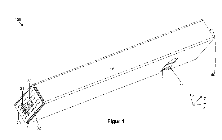
Figure 1 shows parts of a door drive 100 according to an
embodiment of the invention. This embodiment is configured for
a door leaf which is independently actuated by a door drive 100.
-8-
For the sake of clarity, the driving components of the door drive
100 are not illustrated.
The door drive 100 has a mounting plate 1, which, in a known
way, is affixed to a likewise not illustrated carrying body, such
as a door casing, a door transom, a door leaf or the like.
A covering hood 10 is "put over" the mounting plate 1 so the
latter is concealed to the outside. In Figure 1 at least at the side
1o pointing downwards, namely in -z coordinate direction,
preferably however also at the opposite non-visible side,
namely pointing into the +z coordinate direction, the covering
hood 10 has a respective recess, or opening 11, which serves
to expose the respective end of an output shaft of the door drive
100 so it can be coupled in a known manner for example to a
driving linkage system.
In Figure 1, a lateral screen 20, by way of example in the shape
of a perforated screen, is disposed at the left side, which screen
frontally terminates the entire covering, respectively the
covering hood 10 and therefore frontally encases, respectively
covers the door drive 100. This means the lateral screen 20 has
the function of a terminal cap and, in the illustrated example,
allows for disposing a switch member 30, by way of example
having two switches 31, 32. In this case, to the left of the
switches 31, 32, again by way of example, the lateral screen 20
-9-
has matrix-like disposed through-openings which form a
ventilating grille 21.
The ventilating grille 21 serves the purpose of letting air flow
into the inside between the covering hood 10 and the mounting
plate 1 or of evacuating warm air from the inside to the outside.
Warm air develops when operating such electric door drives
100, i.e. motor-driven door drives. Heat development may occur
in the door drive 100, when a motor 101 of the door drive 100,
1o illustrated in Figure 2, is under load while opening, respectively
closing the connected door leaf, respectively when the electrical
components, such as the power supply units and the like, for
supplying power and controlling, are under load. If the heat
would not be evacuated, the door drive 100 could overheat and
be damaged. The same may obviously apply to potential other
components such as a light curtain, radar alarm or the like,
which may be likewise covered by the covering hood 10. In
order to prevent damage, the heat needs to be evacuated, by
either convection or by active ventilators. In order to guarantee
ventilation, cold air needs to be supplied to at least one location
from the outside to said inside and, at least at one other
location, it needs to be evacuated from said inside to the
outside.
If a frontal side or the lateral screen 20 thereof is disposed to
have a minimum distance to a neighbouring wall, so the air can
-10-
flow unhindered into one frontal side of the arrangement 20 and
flow out of the other frontal side, the solution embodied by the
aforementioned ventilation grille 21 is suggested. A lateral
screen 40, which will be explained later in detail, is disposed at
the right concealed end in Figure 1, which, with respect to the
air flow, is configured similarly to the lateral screen 20. Thereby
an almost invisible air flow is realized.
Figure 2 shows the door drive 100 of Figure 1 without the
1o covering hood 10, but with a lateral screen 20 which is modified
compared to Figure 1. In this case, as can be seen, the
ventilating grille 21 is omitted. As driving components, the door
drive 100 has the above mentioned motor 101, the non-visible
driving shaft thereof, to the right side in Figure 2, being
operatively coupled to a gear, which is received in a housing
103. In Figure 2, in the right terminal area of the gear housing
103, a connecting module 110 is attached to the latter.
The connecting module 110 mainly serves to electrically couple
the door drive 100 to an external power supply and has
appropriate electrical connections not illustrated in detail.
By way of example, the motor 101 has a drive shaft exiting at
both sides. The end exiting on the left side is operatively
coupled to a blocking device 102, which, for example, may be a
part of a non-illustrated closing sequence control.
-11-
A system carrier 120 of the door drive 100 is located adjacent to
the left side of the gear housing 103. Preferably the system
carrier 120 is adapted to stationarily receive or to retain
additional driving components such as power supply unit,
driving control, sensors and the like.
The lateral screen 20 and the switch member 30, as will be
explained below, are preferably affixed to the left frontal side of
1o the system carrier 30, namely at the side facing away from the
gear housing 103.
Figure 3 shows partial views of the door drive 100 of Figure 1,
with regard to affixing the switch member 30 of Figure 1,
respectively in an enlarged cut out. In this case, Figure 3a
shows the door drive 100 in an arrangement of Figure 1 without
the covering hood 10 and mounting plate 1. Figure 3b shows
this arrangement in a section along a line A-A of Figure 3a in an
essentially rear perspective, which differs from Figure 3a.
As shown in Figure 3a, by way of example at its left frontal side,
the door drive 100 is equipped with an electronic component,
which is configured for example as a switch member 30.
Furthermore, the lateral screen 20 is disposed at this frontal
side, by way of example in the shape of a perforated screen.
The lateral screen 20 terminates the frontal side of the door
-12-
drive 100. This means the lateral screen 20 has the function of
a terminal cap and, in the illustrated example, allows for
disposing the switch member 30, which by way of example, has
two switches 31, 32. Below the switches 31, 32, the lateral
screen 20 has through-openings which are disposed in a matrix
and form the aforementioned ventilating grille 21.
As indicated above, the ventilating grille 21 serves the purpose
of having air flow into the inside chamber, between the non-
1o illustrated covering hood 10 and through the driving
components 101 to 103, in this case indicated by way of
example, or to evacuate warm air from this inside chamber to
the outside. With regard to the system carrier 120 and the
connecting module 110, the air may likewise flow through these
parts of the door drive 100 in order to cool additional
components such as the power supply unit, the control and the
like.
By way of example, the switch member 30 comprises a printed
circuit board 33 on which the switches 31, 32 are disposed.
Furthermore, a connecting cable 34 starts at the printed circuit
board 34 and leads to a non-illustrated control device. During
installation, the switch member 30 is inserted into the system
carrier 120 from the top in Figure 3, preferably without any
additional fastening means. Thereafter, the lateral screen 20 is
placed onto the system carrier 120 at the frontal side thereof.
-13-
By way of example, the system carrier 120 comprises a support
surface 122. The support surface 122 thus forms a support for
the switch member 30, respectively the printed circuit board 33
thereof.
Preferably the switches 31, 32 of the switch member 30 offer
support in the system carrier 120. As shown in Figure 3c, the
system carrier 120 preferably has latching projections 123,
1o which extend towards each other at the side of the switch
member 30. Each switch 31, 32 has a plate-shaped part
including a break-through for a respective electrical switch
element 31 a, 32a of the respective switch 31, 32. By way of
example, the switch elements 31a, 32a are configured as
rocker switches. The plate-shaped parts serve as support
portion 31b, respectively 32b. The switches 31, 32, with their
portions 31 b, 32b, come to bear on the latching projections 123
from the outside with regard to the system carrier 120. Towards
the printed circuit board 33 of the switch, preferably resiliently
configured clamping portions 31c, 32c, which are configured
laterally at the switches 31, 32 and respectively protrude in the
direction of the associated latching projection 123, are adjacent
to the portions 31b, 32b. They are configured in such a way
that, with the support portions 31b, 32b, they surround the
latching projections 123, so the switches 31, 32 are supported
and the entire switch member 30 is held in position.
-14-
The installation procedure is as follows: Initially, the printed
circuit board 33 of the switch is inserted from the top, namely in
the -y coordinate direction in Figure 3c, into the system carrier
120. Once the latching projections 123 are located between the
clamping portions 31c, 32c and the printed circuit board 33 of
the switch, the switches 31, 32 are simply pushed as far
towards the latching projections 123, namely in the
+x coordinate direction in Figure 3c, until the clamping portions
31c, 32c have overcome the latching projections 123, and
therefore latch therein and the switch member 30 has thus
reached the position shown in Figure 3c.
Figure 4 shows partial views of the door drive 100 of Figure 1
with regard to mounting the lateral screen 20. In this case,
Figure 4a is a sectional view through the system carrier 120
along a line, which is displaced a little bit in the direction of the
lateral screen 20 and parallel to line A-A. The lateral screen 20
has through-openings, respectively switch openings 22 for the
switches 31, 32 to pass therethrough, so once installed, the
switches can be manipulated from the outside.
In order to have air circulate from the lateral screen 20,
respectively the ventilating grille 21 thereof to the parts of the
door drive 100, respectively in opposite direction, the system
carrier 120 has a through-opening 121, which, in the installed
-15-
condition, is aligned with a cooling air flow passing through the
ventilating grille 21.
At the side facing the system carrier 120, the lateral screen 20
has fastening devices in the shape of projections 23, 24
projecting in the direction of the system carrier 120. By way of
example, they include a quadrangle with rounded corners. The
projections 23 thus disposed in the corner areas of this
quadrangle serve to push the lateral screen 20 onto the system
1o carrier 120 in a guided manner. In cross-section, the thus
configured push-on projections 23 are not straight, but angled,
respectively as illustrated here and seen in the longitudinal
direction of the system carrier 120, they are configured to be
concave and arched at the sides facing each other. At
corresponding locations, the system carrier 120 has essentially
complementary guiding portions 124, namely configured to be
convex. This is how the lateral screen 20 is already pre-
positioned when being pushed-on, respectively when being
inserted into the system carrier 120, just the insert depth is not
determined yet.
In order to be able to fix the insert depth of the lateral screen
20, a latching mechanism is provided in this case. The arched
shape of the projections 23 interferes with a flexible resiliency of
the projections 23. Therefore, they are rather not suited for a
latching mechanism. This is why, in addition, the
-16-
aforementioned projections 24 are provided, which in cross-
section are configured to be flat and resilient. At their free ends,
by way of example the latching projections 24 have latching
noses 25 facing each other. When being inserted into the
system carrier 120, the latching noses 25 reach engagement
with corresponding latching recesses of the system carrier 120.
In the illustrated example, these latching recesses are
configured by means of a respective latching groove portion
125 of the system carrier 120. Each latching groove portion 125
1o has a plurality of latching grooves which are not identified in
detail, extend parallel with regard to each other and essentially
transversely to the insertion direction of the lateral screen 20. In
Figure 4b, the insertion direction is suggested by means of a
block arrow. It is thereby possible, depending on the respective
conditions, to be able to vary the insertion depth of the lateral
screen 20.
Figure 4a shows particularly well the latching engagement of
the latching noses 25 in a respective latching groove, in this
case of a visible portion 125. Figure 4b shows the disposition
prior to installing the lateral screen 20 along the block arrow.
Obviously, instead of several latching grooves, respectively one
latching recess corresponding to the latching nose 25 may be
configured, however linked to the disadvantage of the missing
variable insertion depth.
-17-
This positioning mechanism allows for an installation, which
simply consists of inserting the lateral screen 20 into the system
carrier 120, respectively of pushing it on the latter. The portions
23, 24, 124 ensure that the above described switches 31, 32
can pass through the associated through-openings 22 of the
switch member 20, and that, as already described above and
by way of example, the ventilating grille 21, for the cooling air
stream, is aligned with the aeration opening, respectively
1o through-opening 121 of the system carrier 120.
Figure 4c shows the system carrier 120 in the direction of the
frontal face facing the non-illustrated lateral screen 20.
Furthermore, as can be seen, the system carrier 120 has two
projections 126, which extend in the direction of the lateral
screen 20 and serve as an abutment, respectively as a contact
surface for the non-illustrated lateral screen 20. This means, the
abutment projections 126 determine the maximum insertion
depth of the lateral screen 20 with regard to the system carrier
120.
Figure 5 shows the connecting module 110 of the door drive
100 in different views, each time in conjunction with a lateral
screen 40. In this case, the lateral screen 40 closes the frontal
face which is opposite to the one in Figure 3 of the door drive
100 represented by means of the connecting module 110. An
-18-
exemplary ON-OFF switch 2 for the door drive 100 passes
through the lateral screen 40, similarly to the lateral screen 20.
Preferably, the lateral screen 40 is latched to the connecting
module 110. By way of example, this is done by means of two
tongues as the fastening projections 43, only one being visible
in Figure 5a. By means of a latching recess 44, each fastening
projection 43 latches with an associated latching nose 111
configured at the connecting module 110.
1o Figure 5b shows the disposition of Figure 5a from another
perspective and prior to installing the lateral screen 40 onto the
connecting module 110 in the direction of the block arrow. In
this case, the two fastening projections 43, in the shape of a
respective latching tongue, with a respective latching recess 44
located inside, are particularly well visible. Furthermore,
preferably an additional fastening projection 45 with a latching
nose 46 is provided, which is configured at the free end of the
fastening projection 45. In the illustrated example, the latching
nose 46 is configured so that the latching projection thereof (not
indicated) points upwards in Figure 5b. In the installed
condition, the latching nose 46 engages behind an associated
latching surface 112 of the connecting module 110. Thereby,
the lateral screen 40 is kept in the installed position by means
of three latching mechanisms 111, 43, (44) and 112, 46. In
addition and by way of example, the lateral screen 40 has a
through-opening 41 which serves for the above indicated switch
-19-
2 to pass therethrough. Furthermore, preferably the lateral
screen 40 has insert projections 42 which protrude in the
direction of the connecting module 110. They engage, as can
be seen in Figure 5c, in corresponding insert openings 113 of
the connecting module 110. The fastening projections 43, 45
are thereby relieved from positioning the lateral screen 40 at the
connecting module 110. In addition, a latching nose 46, a
latching projection 43 with latching opening 44, as well as the
latching nose 46 with associated latching surface 112 can be
1o seen.
Preferably the lateral screen 40 has moreover pre-punched
break-away areas 47, for example to possibly pass external
power supply lines through the broken-away areas 47 of the
lateral screen 40.
Figure 6 shows the system carrier 120, the connecting module
110 and the covering hood 10 in an exploded view. In order to
fasten the covering hood 10, at surfaces, facing each other, of
its non-identified lateral legs, the hood has groove-shaped
recesses 12, which preferably extend over the entire length of
the covering hood. When placing the hood along the block
arrow, the recesses 12 reach a latching engagement with
corresponding projections 127, 114, in this case only visible at
one side, of the system carrier 120, respectively of the
connecting module 110, what represents a very simple
-20-
mounting of the covering hood 10. Instead of several latching
projections 127, or 114, respectively one latching projection
127, or 114 may be provided, which is configured to be
continuous.
Figure 7 shows an installation method for the encasing, which is
composed of the lateral screen(s) 20, 40 and of the covering
hood 10. After starting with step S1, if electronic components
(for example the switch member 30) in conjunction with one of
1o the lateral screens 20, 40 are to be mounted (branch YES
following step S2), in a subsequent step S3 the respective
component is placed onto the respective fastening device(s)
122, 123 of the door drive 100 or they are inserted into the
device(s). Thereupon, or if no more electronic components are
to be installed (branch NO following step S2), in a following step
S4, the one or more lateral screens 20, 40 are placed onto the
associated fastening device(s) 124, 125, 127 of the door drive
100 or are inserted into the device(s). Finally, in a step S5, the
covering hood 10 is placed onto the door drive 100, or better
onto the fastening devices 114, 127. Should one of the lateral
screens 20, 40 be spaced apart from the covering hood 10, in
an additional step, not-illustrated in this case, it may be
provided to move these lateral screens 20, 40 further towards
the covering hood 10. Thereupon the installation is finished in a
step S6.
-21 -
Figure 8 shows an installation method which, compared to
Figure 7, is modified. Unlike in the previous embodiment, the
steps S4 and S5 are interchanged. This means the covering
hood 10 is mounted prior to mounting the lateral screens 20,
40. This is advantageous in that the lateral screens 20, 40 can
be correctly installed with regard to their insert depth when
putting them in place, because the covering hood 10 is already
installed.
1o The invention in its configuration is not limited to the above
described embodiments.
The fastening devices 23 to 25; 42 to 46 of the lateral screens
20, 40 may be interchanged or they may be combined with
each other. In this case, the system carrier 120 and the
connecting module 110 are correspondingly configured.
Instead of the system carrier 120 and of the connecting module
110, other parts as well, such as the gear housing 103, may be
configured to stationarily receive one of the respective lateral
screens 20, 40.
The latching recesses 12 and the corresponding latching
projections 127, 114 may be interchanged. Furthermore, these
latching means may be configured at other parts, such as at the
gear housing 103.
-22-
The door drive 100 may be replaced by any type of door drive
or door closer, as long as it includes fastening devices for
lateral screens.
The above described installation method may be modified in so
far that in case of two lateral screens 20, 40, the steps S3 and
S4 are processed in an interlaced manner. This means, the
electronic components for a lateral screen 20, 40 are installed
(S3). Thereupon, the associated lateral screen 20, 40 is
installed (S4). Thereupon, the electronic components for the
other lateral screen 40, 20 are installed (S3). Finally, the
second lateral screen 40, 20 is installed (S4).
The through-openings of the above described ventilating grille
21 may be likewise used to make switches or display elements
accessible, respectively visible from the outside.
As a result, the invention provides a simple and installation-
friendly covering, respectively a facing for a door operator.
-23-
List of reference numerals
1 mounting plate
2 switch
10 covering hood
11 recess
12 latching recess
20 lateral screen
21 ventilating grille
22 switch opening
23 fastening projection
24 fastening projection
25 latching nose
30 switch member
31 switch
31 a switch portion
31 b support portion
31 c clamping portion
32 switch
32a switch portion
32b support portion
32c clamping portion
33 printed circuit board of the switch
-24-
34 connecting cable
40 lateral screen
41 switch opening
42 insert projection
43 fastening projection
44 latching opening
45 fastening projection
46 latching nose
47 break-away area
100 door drive
101 motor
102 blocking device
103 gear housing
110 connecting module
111 latching nose
112 latching surface
113 insert opening
114 latching projection
120 system carrier
121 through opening
122 support surface
123 latching projection
124 guide portion
125 latching groove portion
-25-
126 projection
127 latching projection
x coordinate
y coordinate
z coordinate
S1-S6 step