Sélection de la langue

Search

Sommaire du brevet 2781172 

Énoncé de désistement de responsabilité concernant l'information provenant de tiers

Une partie des informations de ce site Web a été fournie par des sources externes. Le gouvernement du Canada n'assume aucune responsabilité concernant la précision, l'actualité ou la fiabilité des informations fournies par les sources externes. Les utilisateurs qui désirent employer cette information devraient consulter directement la source des informations. Le contenu fourni par les sources externes n'est pas assujetti aux exigences sur les langues officielles, la protection des renseignements personnels et l'accessibilité.

Disponibilité de l'Abrégé et des Revendications

L'apparition de différences dans le texte et l'image des Revendications et de l'Abrégé dépend du moment auquel le document est publié. Les textes des Revendications et de l'Abrégé sont affichés :

  • lorsque la demande peut être examinée par le public;
  • lorsque le brevet est émis (délivrance).
(12) Brevet: (11) CA 2781172
(54) Titre français: DISPOSITIF D'ELEMENT D'USURE POUR UN OUTIL DE TRAVAIL
(54) Titre anglais: WEAR PART DEVICE FOR A WORK TOOL
Statut: Accordé et délivré
Données bibliographiques
(51) Classification internationale des brevets (CIB):
  • A01B 15/06 (2006.01)
  • A01B 23/02 (2006.01)
  • E02F 09/28 (2006.01)
(72) Inventeurs :
  • SKJAEVELAND, MAGNE (Norvège)
(73) Titulaires :
  • KVERNELAND GROUP OPERATIONS NORWAY AS
(71) Demandeurs :
  • KVERNELAND GROUP OPERATIONS NORWAY AS (Norvège)
(74) Agent: SMART & BIGGAR LP
(74) Co-agent:
(45) Délivré: 2017-10-31
(86) Date de dépôt PCT: 2010-12-15
(87) Mise à la disponibilité du public: 2011-06-23
Requête d'examen: 2015-09-02
Licence disponible: S.O.
Cédé au domaine public: S.O.
(25) Langue des documents déposés: Anglais

Traité de coopération en matière de brevets (PCT): Oui
(86) Numéro de la demande PCT: PCT/NO2010/000461
(87) Numéro de publication internationale PCT: NO2010000461
(85) Entrée nationale: 2012-05-17

(30) Données de priorité de la demande:
Numéro de la demande Pays / territoire Date
20093547 (Norvège) 2009-12-17

Abrégés

Abrégé français

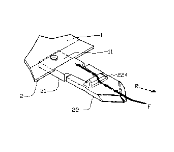
L'invention porte sur un dispositif remplaçable (22) d'élément d'usure destiné à être fixé sur un bord antérieur (2) d'un outil de travail (1), au moins une partie du bord antérieur (2) étant constituée d'un support d'élément d'usure (21), l'élément d'usure (22) étant doté d'une première surface coulissante (222), et le support d'élément d'usure (21) étant doté d'une seconde surface coulissante (213) conçue fondamentalement comme une extension de ladite première surface coulissante (222), et la seconde surface coulissante (213) étant dotée d'une surface de bord coulissante antérieure (214) définissant la surface coulissante (213) vis-à-vis de l'élément d'usure (22), une éminence (224) étant disposée sur la première surface coulissante (222), laquelle éminence est conçue de façon à pouvoir orienter un écoulement de matériau (F) à l'écart d'au moins une partie de la surface coulissante (213) du support d'élément d'usure (21).


Abrégé anglais

There is described a replaceable wear part device (22) for attachment on a forward edge (2) on a work tool (1), where at least a portion of the forward edge (2) is formed of a wear part holder (21), as the wear part (22) is provided with a first sliding surface (222), and the wear part holder (21) is provided with a second sliding surface (213), which essentially is arranged as an extension of said first sliding surface (222), and the second sliding surface (213) is provided with a forward sliding edge surface (214) defining the sliding surface (213) against the wear part (22), where on the first sliding surface (222) is arranged an eminence (224) arranged to be able to lead a material flow (F) away from at least a portion of the sliding surface (213) of the wear part holder (21).

Revendications

Note : Les revendications sont présentées dans la langue officielle dans laquelle elles ont été soumises.


9
claims
1. A
replaceable wear part device for attachment on a forward
edge of a work tool, wherein at least a portion of the
forward edge of the work tool comprises an attachment
section having spaced engagement surfaces, the wear part
device comprising:
a rear edge having an attachment section with spaced
engagement surfaces,
wherein the attachment section of the wear part device is
complementary to the attachment section of the work tool,
wherein the respective engagement surfaces are configured
to be mutually and slidably engageable so as to hold the
wear part device when the wear part device is attached to
the work tool,
wherein the wear part device further comprises an
elongated eminence arranged crosswise to an intended
operating direction of the work tool and immediately
forward of the attachment section of the wear part,
wherein the eminence extends laterally across a first
sliding surface by a distance at least equal to a distance
between the mutually engaged engagement surfaces,
wherein the eminence is configured such that material
dislodged by the work tool is deflected by the eminence
away from the attachment section of the work tool.

10
2. The device according to claim 1, wherein the eminence is
provided with a front surface tilting in the operating
direction of movement of the work tool from a top of the
eminence toward the first sliding surface.
3. The device according to claim 1 or claim 2, wherein the
eminence exhibits a height from the first sliding surface
to a top of the eminence, and wherein the height is at
least 10mm.
4. The device according to claim 1 or claim 2, wherein the
eminence exhibits a height from the first sliding surface
to a top of the eminence, and wherein the height is at
least 12mm.
5. The device according to any one of claims 1 to 4, wherein
the eminence is arranged adjacent to the rear edge of the
wear part device, and wherein the rear edge forms an
abutment for the attachment section of the work tool.

Description

Note : Les descriptions sont présentées dans la langue officielle dans laquelle elles ont été soumises.


CA 02781172 2012-05-17
WO 2011/074983 PCT/N02010/000461
1
WEAR PART DEVICE FOR A WORK TOOL
The invention relates to a replaceable wear part device for
attaching to the forward edge of a work tool, where at least
a portion of the forward edge is formed by a wear part
holder, as the wear part is provided with a first sliding
- surface, and the wear part holder is provided with a second
sliding surface, which is essentially arranged as an exten-
sion of said first sliding surface, and the second sliding
surface is provided with a forward sliding edge surface de-
fining the sliding surface against the wear part, more par-
ticularly by there on the first sliding surface being ar-
ranged an eminence arranged to be able to lead a material
flow away from at least a portion of the wear part holder's
sliding surface.
From work tools provided with an edge, rim, prong, tooth or
the like arranged to be able to work against and move uncom-
pacted material such as earth, gravel, pebbles etc., it is
known to use replaceable wear parts to increase the working
life of the portion/portions being exposed to hard wear. The
applicant's own patent publication EP 1259105 discloses such
a wear part for fitting to a forward edge of a work tool, as
a holder is arranged on the work tool and forms at least a
portion of the forward edge, and the wear part is provided
with cooperating guide elements forming a slidable fit of the
bell-and-spigot type for quick replacement of the wear part

CA 02781172 2017-01-11
2
without the use of attachment means or other means than a
hitting tool.
It has turned out that on some types of tools, such as ploughs
and cultivators, said wear part holder is exposed to as high
wear as the wear part itself. In such situations the benefit of
a replaceable wear part is lost by the very fact that the wear
part and the wear part holder has the same working life and must
be replaced simultaneously.
SUMMARY
n It is therefore desirable to remedy or reduce at least one of
the disadvantages of the prior art, or at least provide a useful
alternative to prior art.
In an aspect, there is provided a replaceable wear part device
for attachment on a forward edge of a work tool, wherein at
n least a portion of the forward edge of the work tool comprises
an attachment section having spaced engagement surfaces, the
wear part device comprising: a rear edge having an attachment
section with spaced engagement surfaces, wherein the attachment
section of the wear part device is complementary to the
20 attachment section of the work tool, wherein the respective
engagement surfaces are configured to be mutually and slidably
engageable so as to hold the wear part device when the wear part
device is attached to the work tool, wherein the wear part
device further comprises an elongated eminence arranged
25 crosswise to an intended operating direction of the work tool
and immediately forward of the attachment section of the wear
part, wherein the eminence extends laterally across a first
sliding surface by a distance at least equal to a distance
between the mutually engaged engagement surfaces, wherein the

CA 02781172 2017-01-11
2a
eminence is configured such that material dislodged by the work
tool is deflected by the eminence away from the attachment
section of the work tool.
In the following the term "length" unless otherwise expressly
s said, is to be understood as the extent of en element in the
operative direction of movement of a wear part when the wear
part is arranged on the forward edge of a work tool, and
possibly the extent of an axis lying in a plane coincident with
said direction of movement. The term "width", unless otherwise
n expressly said, is then to be understood as the extent of the
element perpendicularly to said plane coincident with the
operational direction of movement of the wear part. By the term
"height", unless otherwise expressly said, is then to be
understood as the extent of the element upward from a plane
Is coincident with that side face on the wear part that the element
is arranged on.
On a wear part for a forward edge on a work tool provided with
an edge, rim, prong, tooth or the like arranged to be able to
work against and move uncompacted material such as earth,
20 gravel, pebbles etc., there is on a sliding face

CA 02781172 2012-05-17
WO 2011/074983 3 PCT/N02010/000461
tilted relative to and facing in the operative direction of
movement of the wear part, at least partly crosswise to said
direction of movement and spaced from the delimitation of the
sliding surface against the corresponding sliding face of a
wear part holder arranged an extended ridge, in the following
also called an eminence. The eminence extends at least over a
part of the width of the sliding surface and is advanta-
geously arranged perpendicularly to said operative direction
of movement. The width-wise extent of the eminence is at
least as large as the width-wise extent of contact surfaces
arranged between the wear part and the adjacent wear part
holder. The height of the eminence over the sliding surface
is preferably at least 10mm, and advantageously at least
12mm. At least against the front of the wear part, the back
exhibits preferably a tilted side face. The eminence is ad-
vantageously arranged as close to the wear part holder as
technically possible, as a rear side face of the wear part
defines the eminence.
Through extensive test operation it has surprisingly turned
out that said ridge has a very positive effect on the working
life of the wear part holder relative to the wear part with-
out the working life of the wear part being impaired. The ef-
fect is most probably due to the ridge leading the material
flow to a sufficient degree away from the proximal, down-
stream sliding surfaces and also the interconnecting parts
between the wear part and the wear part holder, so that these
to a lesser extent come into contact with the material flow.
In adhesive earth masses some earth builds up on a portion
downstream of the eminence, an indication that the material
flow pressure against the sliding surfaces has been greatly
reduced. By making the eminence of a material having at least
as good wear properties as the rest of the wear part, the
eminence maintains its protective effect in a large part of

CA 02781172 2012-05-17
WO 2011/074983 4 PCT/N02010/000461
the working life of the wear part, as the working life of the
wear part in the main is determined by how fast it is short-
ened down by wearing down of the forward edge of the wear
part.
More particularly the invention relates to a replaceable wear
part device for a work tool for attaching on a forward edge
of a work tool, where at least a portion of the forward edge
is formed by a wear part holder, as the wear part is provided
with a first sliding surface, and the wear part holder is
lo provided with a second sliding surface essentially arranged
as an extension of said first sliding surface, and the second
sliding surface being provided with a forward sliding surface
edge defining the sliding surface against the wear part, cha-
racterized in that on the first sliding surface is arranged
an eminence arranged to be able to lead a material flow away
from at least a portion of the sliding surface of the wear
part holder.
The eminence may have an extension essentially cross-wise the
operative direction of movement of the work tool. This gives
better utilisation of the wear part material without the
sliding surface properties of the wear part being impaired
worth mentioning.
The cross-wise extension of the eminence may at least be co-
incident with a width-wise extension of fastening elements
arranged on the wear part holder and the wear part. Protec-
tion of portions of the wear part and the wear part holder
being of essential significance for the fastening of the wear
part in the work tool is thereby achieved.
The eminence may be provided with a front surface tilting in
the operative direction of movement of the work tool from an
eminence top toward the first side surface. Thereby is pro-

CA 02781172 2012-05-17
WO 2011/074983 5 PCT/N02010/000461
vided an inclined plane improving the material flow over the
wear part.
The eminence may exhibit a height from the first side surface
to the eminence top of minimum lOmm, and more advantageously
minimum 12mm. This has turned out to give sufficient effect
on the working life of the wear part holder without impairing
worth mentioning the material flow over the wear part.
The eminence may be arranged adjacent a rear edge of the wear
part. Such a positioning gives a maximum extension of the
area of the wear part holder being influenced by the emi-
nence.
In the following is described an example of a preferred em-
bodiment illustrated in the accompanying drawings, wherein:
Fig. 1 shows a section of a forward edge on a schemati-
cally pictured work tool in perspective, where a
wear part holder is attached;
Fig. 2 shows a wear part according to the invention in
perspective;
Fig. 3 shows at a smaller scale a perspective view of an
assembled work tool having a wear part of the in-
vention;
Fig. 4 shows at a larger scale a plan view of the wear
part and also a section of the wear part holder
socket; and
Fig. 5 shows a longitudinal section through the wear part
as indicated V-V in figure 2.
Referring now to the drawings in the following, there Will
now be described preferred embodiments of a replaceable wear

CA 02781172 2012-05-17
WO 2011/074983 6 PCT/N02010/000461
part of the invention adapted for fitting on a work tool hav-
ing one or more working, forward edges or fronts arranged to
be able to work in a specific material, and which is exposed
to wear over time.
The preferred embodiment examples being described are associ-
ated with earth working tools for use in agriculture, but it
is to be understood that the invention has further applica-
tion, as it may be used on replaceable working blades of per
se known kind, and for other types and combinations of work-
lo ing tools requiring fitting of replaceable working blades
held on by a wear part holder whose working life is desired
prolonged.
On a working tool 1 is formed an attachment portion 11 for a
replaceable forward edge element 2. The edge element 2 may be
formed as a blade or shear on a plough or as a leveling
blade, a jaw on an excavator bucket, an end portion on a cul-
tivator prong etc. On the edge element 2 is integrated a wear
part holder 21, shown here attached to the working tool 1 by
means of an attachment bolt 112 led through a portion of the
wear part holder 21 and the edge element 2. The wear part
holder 21 is provided with a spigot 211 comprising profiled
contact faces 212 arranged to engage a corresponding attach-
ment portion 223 on a replaceable wear part 22. The wear part
holder 21 is provided with a sliding surface 213 defined
against the wear part 22 by a forward sliding surface edge
214.
The replaceable wear part 22 is provided with a front portion
221, which in the embodiment example shown has the shape of
an apex arranged to be able to easily penetrate down into a
mass in which the work tool 1 is to be displaced. The wear
part 22 is provided with a sliding surface 222 extending in a
plane approximately in plane with the sliding surface 213 of

CA 02781172 2012-05-17
WO 2011/074983 7 PCT/N02010/000461
the wear part holder 21 and which during the normal working
direction R of the working tool 1 is arranged downstream of
the wear part 22.
An eminence 224 protrudes up from a rear portion of the slid-
ing surface 222 of the wear part 22 and is downstream defined
by a rear edge 227 by the wear part 22 formed at the root of
the attachment portion 223.
The width of the wear part is indicated by reference W1 and
its defined length is shown as L (see figure 4). The width of
the spigot is called W2 (see figure 1).
The wear part eminence 224 has the following dimensions (see
figure 4):
the width-wise extent of the eminence 224 = w
the length-wise extent of the eminence 224 = 1
the height of the eminence 224 above the wear part slid-
ing surface = h
the distance of the eminence 224 from the wear part
holder forward sliding surface edge 214 = d.
The eminence 224 is shown here arranged in the wear part 22
by hot forming, as the eminence 224 is forced out by a for
the purpose suitable tool from the underside of the wear part
22.
The eminence 224 has a width-wise extent w surpassing the
width W2 of the spigot 211 for thereby to form a protection
for at least the spigot 211 and parts of the attachment por-
tions 223 of the wear part 22, as the proximal parts of the
wear part holder 21 and also said, adjacent attachment por-
tions 223 of the wear part 22 are left lying to the lee down-
stream of the eminence 224.

CA 02781172 2012-05-17
WO 2011/074983 8 PCT/N02010/000461
A material flow over the sliding surfaces 213, 222 of the
wear part 22 and the wear part holder 21 is indicated with
arrows F. The effect of the eminence 224 is shown by the
change of direction of the arrow F.
The embodiment example shown is adapted to a production tech-
nology utilizing forging, as the eminence 224 has rounded
shapes on all projecting sides. The eminence is by this pro-
duction method not carried all the way out to the sides of
the wear part 22 to maintain sufficient material thickness in
these portions of the wear part 22 cross-section. In other
production technology, such as in forming by machining and
welding, other shapes of the eminence 224 will be relevant
without this falling outside the scope of the invention.

Dessin représentatif
Une figure unique qui représente un dessin illustrant l'invention.
États administratifs

2024-08-01 : Dans le cadre de la transition vers les Brevets de nouvelle génération (BNG), la base de données sur les brevets canadiens (BDBC) contient désormais un Historique d'événement plus détaillé, qui reproduit le Journal des événements de notre nouvelle solution interne.

Veuillez noter que les événements débutant par « Inactive : » se réfèrent à des événements qui ne sont plus utilisés dans notre nouvelle solution interne.

Pour une meilleure compréhension de l'état de la demande ou brevet qui figure sur cette page, la rubrique Mise en garde , et les descriptions de Brevet , Historique d'événement , Taxes périodiques et Historique des paiements devraient être consultées.

Historique d'événement

Description Date
Représentant commun nommé 2019-10-30
Accordé par délivrance 2017-10-31
Inactive : Page couverture publiée 2017-10-30
Inactive : Taxe finale reçue 2017-09-15
Préoctroi 2017-09-15
Un avis d'acceptation est envoyé 2017-04-26
Lettre envoyée 2017-04-26
Un avis d'acceptation est envoyé 2017-04-26
Inactive : Q2 réussi 2017-04-21
Inactive : Approuvée aux fins d'acceptation (AFA) 2017-04-21
Modification reçue - modification volontaire 2017-01-11
Inactive : Rapport - Aucun CQ 2016-07-11
Inactive : Dem. de l'examinateur par.30(2) Règles 2016-07-11
Requête pour le changement d'adresse ou de mode de correspondance reçue 2015-10-01
Lettre envoyée 2015-09-17
Exigences pour une requête d'examen - jugée conforme 2015-09-02
Toutes les exigences pour l'examen - jugée conforme 2015-09-02
Modification reçue - modification volontaire 2015-09-02
Requête d'examen reçue 2015-09-02
Inactive : Page couverture publiée 2012-08-02
Lettre envoyée 2012-07-23
Demande reçue - PCT 2012-07-11
Inactive : Notice - Entrée phase nat. - Pas de RE 2012-07-11
Inactive : CIB attribuée 2012-07-11
Inactive : CIB en 1re position 2012-07-11
Inactive : Transfert individuel 2012-05-31
Exigences pour l'entrée dans la phase nationale - jugée conforme 2012-05-17
Demande publiée (accessible au public) 2011-06-23

Historique d'abandonnement

Il n'y a pas d'historique d'abandonnement

Taxes périodiques

Le dernier paiement a été reçu le 2016-11-21

Avis : Si le paiement en totalité n'a pas été reçu au plus tard à la date indiquée, une taxe supplémentaire peut être imposée, soit une des taxes suivantes :

  • taxe de rétablissement ;
  • taxe pour paiement en souffrance ; ou
  • taxe additionnelle pour le renversement d'une péremption réputée.

Les taxes sur les brevets sont ajustées au 1er janvier de chaque année. Les montants ci-dessus sont les montants actuels s'ils sont reçus au plus tard le 31 décembre de l'année en cours.
Veuillez vous référer à la page web des taxes sur les brevets de l'OPIC pour voir tous les montants actuels des taxes.

Titulaires au dossier

Les titulaires actuels et antérieures au dossier sont affichés en ordre alphabétique.

Titulaires actuels au dossier
KVERNELAND GROUP OPERATIONS NORWAY AS
Titulaires antérieures au dossier
MAGNE SKJAEVELAND
Les propriétaires antérieurs qui ne figurent pas dans la liste des « Propriétaires au dossier » apparaîtront dans d'autres documents au dossier.
Documents

Pour visionner les fichiers sélectionnés, entrer le code reCAPTCHA :


Pour visualiser une image, cliquer sur un lien dans la colonne description du document. Pour télécharger l'image (les images), cliquer l'une ou plusieurs cases à cocher dans la première colonne et ensuite cliquer sur le bouton "Télécharger sélection en format PDF (archive Zip)" ou le bouton "Télécharger sélection (en un fichier PDF fusionné)".

Liste des documents de brevet publiés et non publiés sur la BDBC .

Si vous avez des difficultés à accéder au contenu, veuillez communiquer avec le Centre de services à la clientèle au 1-866-997-1936, ou envoyer un courriel au Centre de service à la clientèle de l'OPIC.


Description du
Document 
Date
(aaaa-mm-jj) 
Nombre de pages   Taille de l'image (Ko) 
Description 2012-05-16 8 300
Dessins 2012-05-16 2 38
Abrégé 2012-05-16 1 61
Revendications 2012-05-16 2 48
Dessin représentatif 2012-05-16 1 7
Description 2017-01-10 9 325
Revendications 2017-01-10 2 51
Dessin représentatif 2017-10-02 1 5
Avis d'entree dans la phase nationale 2012-07-10 1 205
Courtoisie - Certificat d'enregistrement (document(s) connexe(s)) 2012-07-22 1 125
Rappel de taxe de maintien due 2012-08-15 1 111
Rappel - requête d'examen 2015-08-17 1 116
Accusé de réception de la requête d'examen 2015-09-16 1 176
Avis du commissaire - Demande jugée acceptable 2017-04-25 1 162
PCT 2012-05-16 4 122
Modification / réponse à un rapport 2015-09-01 2 85
Correspondance 2015-09-30 6 186
Demande de l'examinateur 2016-07-10 4 206
Modification / réponse à un rapport 2017-01-10 9 347
Taxe finale 2017-09-14 2 63