Sélection de la langue

Search

Sommaire du brevet 2781485 

Énoncé de désistement de responsabilité concernant l'information provenant de tiers

Une partie des informations de ce site Web a été fournie par des sources externes. Le gouvernement du Canada n'assume aucune responsabilité concernant la précision, l'actualité ou la fiabilité des informations fournies par les sources externes. Les utilisateurs qui désirent employer cette information devraient consulter directement la source des informations. Le contenu fourni par les sources externes n'est pas assujetti aux exigences sur les langues officielles, la protection des renseignements personnels et l'accessibilité.

Disponibilité de l'Abrégé et des Revendications

L'apparition de différences dans le texte et l'image des Revendications et de l'Abrégé dépend du moment auquel le document est publié. Les textes des Revendications et de l'Abrégé sont affichés :

  • lorsque la demande peut être examinée par le public;
  • lorsque le brevet est émis (délivrance).
(12) Brevet: (11) CA 2781485
(54) Titre français: SYSTDME DE PORTE ETANCHE
(54) Titre anglais: WATERTIGHT DOOR SYSTEM
Statut: Accordé et délivré
Données bibliographiques
(51) Classification internationale des brevets (CIB):
  • B63B 43/24 (2006.01)
  • B63B 27/22 (2006.01)
  • B65G 21/20 (2006.01)
  • B65G 49/00 (2006.01)
  • B65G 67/60 (2006.01)
  • E06B 05/00 (2006.01)
  • E06B 07/16 (2006.01)
(72) Inventeurs :
  • ELDER, JOHN (Canada)
  • MONK, DAVID (Canada)
  • STORRING, JOHN (Canada)
  • LEIGH, SCOTT (Canada)
  • SMITH, DOUG (Canada)
(73) Titulaires :
  • EMS-TECH INC.
(71) Demandeurs :
  • EMS-TECH INC. (Canada)
(74) Agent: MILTONS IP/P.I.
(74) Co-agent:
(45) Délivré: 2015-10-13
(22) Date de dépôt: 2012-06-27
(41) Mise à la disponibilité du public: 2013-01-07
Requête d'examen: 2015-01-29
Licence disponible: S.O.
Cédé au domaine public: S.O.
(25) Langue des documents déposés: Anglais

Traité de coopération en matière de brevets (PCT): Non

(30) Données de priorité de la demande:
Numéro de la demande Pays / territoire Date
2,745,544 (Canada) 2011-07-07

Abrégés

Abrégé français

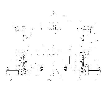
Un système de porte étanche procure une sous-division de soutes de cargo et comporte un ensemble encadrement de porte avec une porte coulissante. Des longerons de support de transporteur sont reliés de manière mobile à la porte coulissante et des rouleaux de transporteur sont reliés de manière mobile aux longerons de support de transporteur. Un actionneur linéaire associé à lensemble encadrement de porte actionne sélectivement la porte entre une position ouverte et fermée, alors que lactivation de la porte par le vérin hydraulique amène les longerons de support de transporteur à se déplacer avec la porte et les rouleaux de transporteur à sabaisser sans être retirés. Des connecteurs sur le côté des bandes sont placés sur chaque côté de lensemble encadrement de porte et peuvent être déplacés les deux vers lintérieur contre un bord de la bande transporteuse et vers lextérieur à partir du bord de la bande transporteuse.


Abrégé anglais

A watertight door system that provides for subdivision of cargo holds, and having a door frame assembly with a sliding door. Conveyor support stringers are movably connected to the sliding door and conveyor idlers are movably connected to and the conveyor support stringers. A linear actuator associated with the door frame assembly selectively actuates the door between an open and closed position, whereby actuation of the door by the hydraulic cylinder causes the conveyor support stringers to move with the door, and the conveyor idlers to be lowered without removal thereof. Belt side plugs are positioned on either side of the door frame assembly, and can move both inwardly against a conveyor belt edge and outwardly from the conveyor belt edge.

Revendications

Note : Les revendications sont présentées dans la langue officielle dans laquelle elles ont été soumises.


WE CLAIM:
1. A door for an opening in a bulkhead comprising:
a door frame assembly having a sliding door thereon;
at least one conveyor support stringer connected to and movable with the
sliding
door;
at least one conveyor idler connected to and movable with the at least one
conveyor support stringer; and
a linear actuator associated with the door frame assembly, for selectively
actuating the door between an open and closed position,
whereby actuation of the door by the linear actuator causes the at least one
conveyor support stringer to move with the door, and the at least one conveyor
idler to
be lowered without removal thereof.
2. The door of claim 1, wherein the linear actuator is mechanical,
electric,
pneumatic or a hydraulic cylinder.
3. The door of claim 1, further comprising vertical frame members
positioned on either side of the sliding door.
4. The door of claim 3, wherein each of the vertical frame members
further comprise a track positioned thereon.
5. The door of claim 4, wherein the sliding door is guided to an open or
closed position by guide posts which extend along a respective track on the
vertical
frame members.
6. The door of claim 1, wherein the at least one conveyor support stringer
is hingedly connected to the sliding door.
7. The door of claim 1, wherein the at least one conveyor support stringer
8

comprises a first set of at least two conveyor support stringers connected to
the sliding
door, the first set of at least two conveyor support stringers being
positioned on a first
side of the sliding door.
8. The door of claim 7, wherein the at least one conveyor support stringer
further comprises a second set of at least two conveyor support stringers
connected to
the sliding door, the second set of at least two conveyor support stringers
being
positioned on a second side of the sliding door.
9. The door of claim 8, wherein a plurality of conveyor idlers are
connected to and movable with the first set of at least two conveyor support
stringers
and with the second set of at least two conveyor support stringers.
10. The door of claim 1, wherein a distal end of the at least one conveyor
idler is pivotally connected to a linkage assembly connected to the at least
one conveyor
support stringer.
11. The door of claim 1, further comprising belt side plugs positioned on
either side of the door frame assembly, the belt side plugs being constructed
and
arranged to move both inwardly against a conveyor belt edge and outwardly from
the
conveyor belt edge.
12. The door of claim 11, further comprising an actuator associated with
each of the belt side plugs, the actuator being positioned on opposed sides of
the door
frame assembly.
13. The door of claim 12, wherein the actuator is a screw thread actuator.
14. The door of claim 12, wherein the actuator is mechanical, electric,
pneumatic or hydraulic.
9

15. The door of claim 1, wherein two belt side plugs are positioned on
either
side of the door frame assembly, the belt side plugs being constructed and
arranged to
move both inwardly against a conveyor belt edge and outwardly from the
conveyor belt
edge.
16. The door of claim 15, wherein one of the belt side plugs is associated
with a top conveyor belt, and another of the belt side plugs is associated
with a bottom
conveyor belt.
17. A door for an opening in a bulkhead comprising:
a door frame assembly having a sliding door thereon; a set of at least two
conveyor support stringers connected to and movable with the sliding door, the
set of at
least two conveyor support stringers being positioned on one side of the
sliding door;
another set of at least two conveyor support stringers connected to the
sliding
door, the another set of at least two conveyor support stringers being
positioned on a
second side of the sliding door;
a plurality of conveyor idlers are connected to and movable with the set of at
least two conveyor support stringers and with the another set of at least two
conveyor
support stringers; and a linear actuator associated with the door frame
assembly, for
selectively actuating the door between an open and closed position,
whereby actuation of the door by the linear actuator causes the conveyor
support
stringers to move with the door, and the plurality of conveyor idlers to be
lowered
without removal thereof.

Description

Note : Les descriptions sont présentées dans la langue officielle dans laquelle elles ont été soumises.


CA 02781485 2012-06-27
WATERTIGHT DOOR SYSTEM
The present invention relates to a watertight door system, or more
particularly, to a
watertight door system that provides for subdivision of cargo holds on a ship
while
minimizing complexity of operation.
BACKGROUND OF THE INVENTION
Watertight doors are an integral part of all ocean-going ships and this
includes gravity
type self-unloading ships. What makes these particular watertight doors
different from
most is that they must close the penetration through which the conveyor must
pass. The
complexity and size of the door can be rather considerable given: (1) the need
for the
doors to seal around both the carrying and return runs of the conveyor, and;
(2) small
leakage rates permitted by IACS, Solas, the regulatory bodies and as
standardized in
ASTM F1196. Several designs have been introduced by different companies over
the
years and, whilst functional, some designs tend to be rather complex in terms
of ease of
operation or mechanical content. Such complexity can require increased
maintenance
and also lead to a more rapid deterioration of components in one faun or
another.
In all cases, the conveyor is supported by idler rolls and these idler rolls
are located
adjacent to, and on both sides of, the watertight door. The conveyor idlers
are typically
supported on rigid structures called 'stringers' that run the length of the
conveyor. The
watertight door is opened prior to conveyor system start-up and prior to
material being
placed on the conveyor belt. The watertight door must be closed prior to the
vessel
leaving port to ensure adequate stability for safety at sea in the event that
one of the
cargo holds is breached and flooded. Depending upon the design of the
watertight door,
the conveyor belt can impose a significant force against the watertight door
during
closing operations and in a closed static case due to residual belt tensions.
In the case of
at least one watertight door design, a multiple of such conveyor idlers are
required to be
removed before the watertight door can be closed due to the external force
imposed on
the door from the belt. In some cases, a ship's crew is required to remove a
number of

CA 02781485 2015-01-29
conveyor idlers (typically three) on either side of the door (for a total of
six), by hand,
before the watertight door can be closed. This is obviously a time consuming
and
laborious chore.
It would therefore be advantageous to have an improved watertight door system
wherein the conveyor belt tensions could be relieved automatically, by
attaching a
section of the adjoining conveyor support stringers on either side of the
door, with those
sections hinged to the watertight door, whereby actuation of the door causes
the
adjoining stringers to move with the door, and the associated conveyor idlers
to be
lowered out of the way without the removal thereof.
It would be further advantageous to have a watertight door system which can be
opened
and closed in an efficient, timely manner, and which is of a non-complex
design that
does not require a multitude of moving components or excessive preventative
maintenance. To this end, the present invention effectively addresses this
need.
SUMMARY OF THE INVENTION
The present invention provides an improved watertight door system wherein the
conveyor idlers would be movable, through connection to adjoining conveyor
support
stringers hinged to the watertight door, whereby actuation of the door causes
the
adjoining stringers to move with the door, and the associated conveyor idlers
to be
lowered out of the way without the removal thereof by other means.
In a broad embodiment, the invention therefore seeks to provide an improved
watertight
door system which can be opened and closed in an efficient, timely manner, and
which
is of a non-complex design that does not require a multitude of moving
components.
According to one aspect of an embodiment of the present invention, there is
provided a
door for an opening in a bulkhead comprising a door frame assembly having a
sliding
2

CA 02781485 2015-01-29
door thereon; at least one conveyor support stringer connected to and movable
with the
sliding door; at least one conveyor idler connected to and movable with the at
least one
conveyor support stringer; and a linear actuator associated with the door
frame
assembly, for selectively actuating the door between an open and closed
position,
whereby actuation of the door by the linear actuator causes the at least one
conveyor
support stringer to move with the door, and the at least one conveyor idler to
be lowered
without removal thereof.
According to another aspect of an embodiment of the present invention, there
is
provided a door for an opening in a bulkhead comprising a door frame assembly
having
a sliding door thereon; a set of at least two conveyor support stringers
connected to and
movable with the sliding door, the set of at least two conveyor support
stringers being
positioned on one side of the sliding door; another set of at least two
conveyor support
stringers connected to the sliding door, the another set of at least two
conveyor support
stringers being positioned on a second side of the sliding door; a plurality
of conveyor
idlers are connected to and movable with the set of at least two conveyor
support
stringers and with the another set of at least two conveyor support stringers;
and a linear
actuator associated with the door frame assembly, for selectively actuating
the door
between an open and closed position, whereby actuation of the door by the
linear
actuator causes the conveyor support stringers to move with the door, and the
plurality
of conveyor idlers to be lowered without removal thereof.
BRIEF DESCRIPTION OF THE DRAWINGS
The embodiments of the present invention will now be described by reference to
the
following figures, in which identical reference numerals in different figures
indicate
identical elements and in which:
Figure lA is a front view of an embodiment of the invention, illustrating the
watertight
door in an open position;
3

CA 02781485 2012-06-27
Figure 1B is a side view of the embodiment of the invention shown in Figure
1A,
illustrating the watertight door in an open position;
Figure 2A is a front view of an embodiment of the invention, illustrating the
watertight
door in a closed position; and
Figure 2B is a side view of the embodiment of the invention shown in Figure
2A,
illustrating the watertight door in a closed position.
DETAILED DESCRIPTION OF THE INVENTION
The invention will be described for the purposes of illustration only in
connection with
certain embodiments; however, it is to be understood that other objects and
advantages
of the present invention will be made apparent by the following description of
the
drawings according to the present invention. While a preferred embodiment is
disclosed, this is not intended to be limiting. Rather, the general principles
set forth
herein are considered to be merely illustrative of the scope of the present
invention and
it is to be further understood that numerous changes may be made without
straying from
the scope of the present invention.
Referring to Figures 1A to 2B, a first exemplary embodiment of the watertight
door
system 1 of the present invention is shown. Normally, of course, a suitably
sized
opening is cut in the bulkhead of the ship (not shown) and it is this bulkhead
opening
that must be sealed when the watertight door is closed.
The watertight door system 1 comprises a door frame assembly 4 which possesses
a
vertical sliding door 10 thereon. The door 10 itself can be moved from an open
to a
closed position by means of a linear actuator 3 (shown in Figures 1A and 2A)
as a
hydraulic cylinder) which is powered by the ship's electric, hydraulic or
pneumatic
system. Preferably, hydraulic system pressure is regulated so as to provide
actuation of
the door, and is typically controlled locally by a designated member of the
ship's crew.
4

CA 02781485 2012-06-27
Typically such doors are closed after completion of discharge and prior to
vessel
departure. They are opened upon vessel arrival at discharge port and prior to
system
start-up.
The door 10, when opened or closed, is guided to an open or closed position by
adjustable guide posts 15, that follow along tracks (not shown) located on
vertical frame
members 2 positioned on either side of the door 10.
Conveyor support stringers 6 adjacent to the door are hinged at one end to the
door 10
itself, the conveyor support stringers 6 having conveyor idlers 5 connected
thereto,
each of the conveyor idlers 5 being attached at each opposed end thereof to
each of the
conveyor support stringers 6. In a preferred embodiment, as seen in Figures 1B
and
2B, there are two conveyor support stringers 6 positioned on one side of the
door 10,
each at opposite ends of the door 10, and there are likewise also two
corresponding
conveyor support stringers 6 on the opposite side of the door 10. Moreover, in
a
preferred embodiment, there are a plurality of conveyor idlers 5 connected to
the
conveyor support stringers 6. Moreover, each distal end of the conveyor
support
stringers 6 is pivotally connected to a simple linkage assembly 11, which is
supported
by a T-Bracket, that is in turn supported on the conveyor stringer assembly
(not shown).
Twin hand wheel operated screw thread actuators 8 (mechanical in nature, as
shown in
Figure 1A) are positioned on either side of the door frame assembly 4 and are
utilized
to independently control and move both carrying side and return side belt side
plugs 69
into contact with the conveyor belt edges to minimize leakage at these points
when the
door 10 is in the closed position. The actuator for the belt side plugs can be
screw type,
as noted, but also can be hydraulic, mechanical, electrical or pneumatic in
operation. As
an example, an operator can actuate the cylinder 8, to cause an associated
linkage (not
shown) to move the belt plug 69 inwardly against the conveyor belt edge.
Similarly,
when the operator actuates the cylinder 8 the other way, this causes the belt
plug 69 to
move outboard clear of the conveyor belt edge.
5

CA 02781485 2012-06-27
In a preferred embodiment, there are two belt plugs 69 per side of the door
frame
assembly 4; one for the top (carrying) conveyor belt and one for the bottom
(return)
conveyor belt. Preferably, separate belt plugs 69 for the top and bottom belts
are
required, as these belts can be offset at the time of closure.
In operation, actuation of the door 10 causes the adjoining conveyor support
stringers 6
to move with the door 10 and the associated conveyor idlers 5 are thus lowered
to the
vessel bottom deck plate (tank top). This action, in combination with a
release of
conveyor belt tension, is necessary to allow the door 10 to be able to push
the two
conveyor belt lines to the stool 70 that is located in line with the door
immediately
below the return belt line. Sealing of the doorway opening is achieved by
compressing
the two belts between the door and the stool 70. Sealing is achieved on the
other three
sides by face seal located between the machined faces on the sliding door and
the
watertight door frame.
As the vertical sliding door is lowered, the conveyor support stringers 6 are
lowered,
and the associated conveyor catenary type idlers 5 simply drop in unison and
adjust to a
neutral position when they strike the top surface of the return belt. Belt
plugs 69 are run
up against associated belt edges and the door 10 is finally closed tightly to
provide
watertightness along the bottom edge and three remaining surfaces. The crew
member
takes no further action in this regard and when it comes time to operate the
conveyor
system, the watertight door is opened which causes the conveyor support
stringers 6 and
supported conveyor idlers 5 to be raised back into operating position.
Other embodiments consistent with the present invention will become apparent
from
consideration of the specification and the practice of the invention disclosed
therein.
6

CA 02781485 2015-01-29
Accordingly, the specification and the embodiments are to be considered
exemplary
only, with the scope of the invention being disclosed by the following claims.
7

Dessin représentatif
Une figure unique qui représente un dessin illustrant l'invention.
États administratifs

2024-08-01 : Dans le cadre de la transition vers les Brevets de nouvelle génération (BNG), la base de données sur les brevets canadiens (BDBC) contient désormais un Historique d'événement plus détaillé, qui reproduit le Journal des événements de notre nouvelle solution interne.

Veuillez noter que les événements débutant par « Inactive : » se réfèrent à des événements qui ne sont plus utilisés dans notre nouvelle solution interne.

Pour une meilleure compréhension de l'état de la demande ou brevet qui figure sur cette page, la rubrique Mise en garde , et les descriptions de Brevet , Historique d'événement , Taxes périodiques et Historique des paiements devraient être consultées.

Historique d'événement

Description Date
Représentant commun nommé 2019-10-30
Demande visant la révocation de la nomination d'un agent 2018-06-06
Demande visant la nomination d'un agent 2018-06-06
Accordé par délivrance 2015-10-13
Inactive : Page couverture publiée 2015-10-12
Préoctroi 2015-07-28
Inactive : Taxe finale reçue 2015-07-28
Exigences relatives à la révocation de la nomination d'un agent - jugée conforme 2015-05-06
Inactive : Lettre officielle 2015-05-06
Exigences relatives à la nomination d'un agent - jugée conforme 2015-05-06
Demande visant la révocation de la nomination d'un agent 2015-04-01
Demande visant la nomination d'un agent 2015-04-01
Un avis d'acceptation est envoyé 2015-03-09
Lettre envoyée 2015-03-09
Un avis d'acceptation est envoyé 2015-03-09
Inactive : Approuvée aux fins d'acceptation (AFA) 2015-02-26
Inactive : Q2 réussi 2015-02-26
Lettre envoyée 2015-02-12
Toutes les exigences pour l'examen - jugée conforme 2015-01-29
Exigences pour une requête d'examen - jugée conforme 2015-01-29
Modification reçue - modification volontaire 2015-01-29
Avancement de l'examen demandé - PPH 2015-01-29
Requête d'examen reçue 2015-01-29
Avancement de l'examen jugé conforme - PPH 2015-01-29
Inactive : Page couverture publiée 2013-01-10
Inactive : CIB attribuée 2013-01-08
Inactive : CIB en 1re position 2013-01-08
Inactive : CIB attribuée 2013-01-08
Inactive : CIB attribuée 2013-01-07
Demande publiée (accessible au public) 2013-01-07
Inactive : CIB attribuée 2013-01-07
Lettre envoyée 2012-09-10
Inactive : Transfert individuel 2012-08-16
Inactive : Certificat de dépôt - Sans RE (Anglais) 2012-07-13
Demande reçue - nationale ordinaire 2012-07-12

Historique d'abandonnement

Il n'y a pas d'historique d'abandonnement

Taxes périodiques

Le dernier paiement a été reçu le 2015-04-10

Avis : Si le paiement en totalité n'a pas été reçu au plus tard à la date indiquée, une taxe supplémentaire peut être imposée, soit une des taxes suivantes :

  • taxe de rétablissement ;
  • taxe pour paiement en souffrance ; ou
  • taxe additionnelle pour le renversement d'une péremption réputée.

Les taxes sur les brevets sont ajustées au 1er janvier de chaque année. Les montants ci-dessus sont les montants actuels s'ils sont reçus au plus tard le 31 décembre de l'année en cours.
Veuillez vous référer à la page web des taxes sur les brevets de l'OPIC pour voir tous les montants actuels des taxes.

Titulaires au dossier

Les titulaires actuels et antérieures au dossier sont affichés en ordre alphabétique.

Titulaires actuels au dossier
EMS-TECH INC.
Titulaires antérieures au dossier
DAVID MONK
DOUG SMITH
JOHN ELDER
JOHN STORRING
SCOTT LEIGH
Les propriétaires antérieurs qui ne figurent pas dans la liste des « Propriétaires au dossier » apparaîtront dans d'autres documents au dossier.
Documents

Pour visionner les fichiers sélectionnés, entrer le code reCAPTCHA :


Pour visualiser une image, cliquer sur un lien dans la colonne description du document. Pour télécharger l'image (les images), cliquer l'une ou plusieurs cases à cocher dans la première colonne et ensuite cliquer sur le bouton "Télécharger sélection en format PDF (archive Zip)" ou le bouton "Télécharger sélection (en un fichier PDF fusionné)".

Liste des documents de brevet publiés et non publiés sur la BDBC .

Si vous avez des difficultés à accéder au contenu, veuillez communiquer avec le Centre de services à la clientèle au 1-866-997-1936, ou envoyer un courriel au Centre de service à la clientèle de l'OPIC.


Description du
Document 
Date
(aaaa-mm-jj) 
Nombre de pages   Taille de l'image (Ko) 
Description 2012-06-26 7 280
Abrégé 2012-06-26 1 19
Dessins 2012-06-26 4 83
Revendications 2012-06-26 4 105
Dessin représentatif 2013-01-09 1 18
Description 2015-01-28 7 279
Revendications 2015-01-28 3 101
Dessin représentatif 2015-09-22 1 13
Paiement de taxe périodique 2024-03-20 2 57
Certificat de dépôt (anglais) 2012-07-12 1 166
Courtoisie - Certificat d'enregistrement (document(s) connexe(s)) 2012-09-09 1 102
Rappel de taxe de maintien due 2014-03-02 1 112
Accusé de réception de la requête d'examen 2015-02-11 1 176
Avis du commissaire - Demande jugée acceptable 2015-03-08 1 161
Correspondance 2015-03-31 3 105
Correspondance 2015-05-05 2 47
Correspondance 2015-05-05 2 66
Taxe finale 2015-07-27 2 59