Note : Les descriptions sont présentées dans la langue officielle dans laquelle elles ont été soumises.
CA 02781710 2012-05-23
Fuel cell system and method for drying of exhaust gas of a fuel cell system
TECHNICAL FIELD:
The invention relates to a fuel cell system with an apparatus for drying
exhaust gases of the
fuel cell system, to a method for drying exhaust gases of a fuel cell system
and to an aircraft
with at least one such fuel cell system.
BACKGROUND OF THE INVENTION:
For modern commercial aircraft, occasionally fuel cell systems are conceived
or already
used in order to handle various tasks. Apart from electricity generation,
other tasks can also
be carried out, for example rendering a fuel tank inert by introducing the
exhaust gases of a
fuel cell system. Because of the way a fuel cell operates, the exhaust gas
usually contains
water vapor. Generally-speaking, if humid gases are used for rendering a fuel
tank inert,
there is a problem in that fuels, in particular kerosene, are hygroscopic.
Furthermore, there is
a danger that moreover a bacteria population can form in the tank, which
bacteria population
could influence sensors for acquiring the fill level of the tank so that
acquisition becomes
imprecise. Furthermore, within the fuel tank or the fuel itself, ice crystals
could form that
could result in damage to engine injection nozzles and fuel filters in
cruising flight of the
aircraft or during below-zero temperatures on the ground. There is thus a
requirement for
introducing dry gases into the fuel tank in order to be able to render the
fuel tank inert.
DE 10 2005 054 885 Al and US 2007/0111060 Al disclose a safety system for
reducing the
danger of explosion of a fuel tank, in which system a protective-gas
production device
comprises a fuel cell system with a fuel cell, and provides a protective gas
which during
operation of the fuel cell system is produced by the fuel cell.
In prior art various methods and systems are known which are used for drying
gases, in
CA 02781710 2012-05-23
- 2 -
particular air. Thus it would, for example, be possible to carry out
adsorption by means of
hygroscopic media, for example silica gel. However, the water absorption
capacity of a
hygroscopic medium is finite, and consequently after use it would have to
either be replaced
or regenerated. In particular in an aircraft, replacement leads to pronounced
weight
problems, and constant emptying and refilling leads to increased maintenance
effort.
Furthermore, regeneration would be possible by means of a corresponding heat
input, for
example by means of heated air. However, this would place in doubt the
effectiveness of the
fuel cell system, because thermal regeneration would require considerable
expenditure of
energy. If no regeneration is to be carried out, due to the above-mentioned
saturation,
exhaust gas drying is possible only for a limited period of time. Generally
speaking, in such
methods dew points, i.e. temperatures, are attained at which there is a state
of equilibrium
between condensing water and evaporating water, which dew points or
temperatures reach
far into the double-digit negative region.
A further method for drying air takes place by water transfer by means of a
selective
membrane, with the use of a partial pressure differential. To this effect a
membrane would
be used that separates a gas to be dried from a dry gas, wherein, due to a
partial pressure
differential, water is made to pass through the membrane. As an alternative to
the dry gas it
would also be possible to increase the static pressure on that membrane side
on which the
gas to be dried is located. The drying performance of this method is limited
by the
achievable partial pressure differential. Particularly low dew points of a
membrane
compressed-air dryer are only achieved with the use of quite a high operating
pressure and
the accompanying high compressor performance necessary.
A further, third, method from prior art for gas drying would take place by
cooling the gas to
below the dew point, for which purpose basically only a heat exchanger and a
heat sink or a
cooling medium are required. Following cooling, and for final separation of
liquid water
from gaseous residual gas, a drip catcher or the like could be used. However,
this principle
requires quite considerable cooling capacity because liquid product water is
present, and the
energy released during the phase transition needs to be discharged. The cold
used to cool the
gas can in part be recovered in a downstream recuperative heat exchanger.
Basically, in this
arrangement the attainable dew point is limited by the freezing point, because
in the design
CA 02781710 2016-07-29
- 3 -
currently in widespread use icing occurring within the heat exchanger can
result in the
blocking of gas ducts.
SUMMARY OF THE INVENTION:
Correspondingly, it may be considered an object of the invention to propose a
system for
cooling the exhaust gas of a fuel cell system, which system for cooling
reduces or entirely
eliminates the above-mentioned disadvantages.
In particular it may be considered an object of the invention to propose a
system for drying
exhaust gas of a fuel cell system, which system for drying with the use of as
little energy as
possible makes it possible to dry the exhaust gas as effectively as possible
without
significantly increasing the complexity of the fuel cell system or its
periphery, while at the
same time minimizing the additional weight.
The object may be met by a fuel cell system having an apparatus for drying of
exhaust gas
of the fuel cell system according to the present invention.
According to a first aspect of the invention, the apparatus for drying of
exhaust gas of the
fuel cell system comprises at least one cooling element with at least one
first surface and at
least one detachment device.
The cooling element is designed to be thermally connected to a heat sink and
to come into
contact with gas flowing past the first surface. In concrete terms this means
that a cooling
element of any shape can be connected in any desired manner with a heat sink
in order to be
cooled. In this arrangement connection with the heat sink can be carried out
in completely
different ways. For example, a cooling circuit could be provided that conducts
a cooling
medium as a heat sink through the cooling element so that heat from the
cooling element is
dissipated to the cooling medium. At the same time the cooling element could
also be
designed to establish a mechanical connection with a Peltier element or the
like as a heat
sink so that, as a result of contact with a cold side of a Peltier element,
heat dissipation from
CA 02781710 2012-05-23
- 4 -
the cooling element to the Peltier element, and thus cooling, can take place.
Furthermore, it
could also be possible to link a cold fluid as a heat sink from any source in
any desirable
manner with the cooling element so that, as a result of the low temperature of
the fluid,
cooling of the cooling element takes place. In this arrangement, for example,
particularly
cold ambient air from the surroundings of an aircraft in cruising flight could
be considered,
which air can be used either directly or by way of a heat exchanger
implemented in the form
of an outer-skin cooler. Likewise, the use of liquid hydrogen from a cryogenic
tank could be
considered as a heat sink, which hydrogen is used as fuel for the fuel cell.
In order to operate
a fuel cell it is necessary anyway to convert the hydrogen from its liquid
form to a gaseous
form so that a heat input could be advantageous.
Such a cooling element provides an advantage in that the content of water or
water vapor of
a gas flowing past the first surface of the cooling element freezes and
collects on the first
surface. With an adequately cold temperature of the cooling element below the
freezing
point and adequate impingement of the first surface with the gas to be dried,
adequate drying
of the gas is possible.
The above-mentioned detachment device is movably held relative to the first
surface of the
cooling element and is designed to detach water that has frozen onto the first
surface, and
consequently no excessive deposit of ice occurs. This aspect of the invention
is not limited
to a particular type of detachment device; instead, here too any imaginable
detachment
devices can be considered. Mechanical detachment elements can be implemented
that by
means of scraping elements, scraping edges or the like, engage the first
surface and
mechanically detach ice from the first surface.
The specific disadvantages associated with the devices known from prior art
can be
overcome by the apparatus for drying included in the fuel cell system
according to the
invention. The use of a mechanical detachment device provides a particular
advantage in
that no saturation effects occur. Furthermore, no special materials need to be
fed to the
apparatus, which materials would allow the detachment of ice or drying of the
gas.
Furthermore, a compact design can be anticipated.
CA 02781710 2012-05-23
- 5 -
In an advantageous improvement of the apparatus, the detachment device
comprises an edge
that is designed to scrape off ice from the first surface of the cooling
element. The edge is
thus preferably to be designed in such a manner that its shape corresponds to
the shape of
the first surface. For example, if the first surface is a planar straight
surface, a planar and
straight-line edge could be used to scrape ice from the first surface. In this
manner the
quantity of ice that has accumulated on the first surface is always limited.
Consequently,
continuous adequate heat dissipation for the icing of water vapor of the gas
is possible.
According to an equally advantageous improvement of the apparatus, the cooling
element is
a hollow body, wherein the first surface is an inside surface of the cooling
element. In this
manner, in particular, the introduction and the passing-through of gas is
simplified because
the cooling element by its hollow shape could practically represent an air
line. By thermally
connecting the cooling element with a heat sink, ice collects on the inside
surface of the
cooling element, wherein this ice can be scraped off continuously, step-by-
step or in an
alternating manner.
Equally advantageous is the design of the cooling element in concrete terms as
a body that at
least in some sections is of a hollow-cylindrical shape, because this variant
is particularly
easy to manufacture, and can thus reduce the costs for producing the apparatus
to a low
level.
With the use of a hollow cooling element, particularly with a design that at
least in some
sections comprises a hollow-cylindrical shape, in an advantageous improvement
of the
apparatus it makes sense to use a spindle-shaped detachment device whose outer
spindle
edges are in contact with the inside surface of the cooling element. The
spindle-shaped
detachment device is preferably to be rotatably held on an axis that
corresponds to the axis
of extension of the cooling element. This concentric symmetric design makes
possible
uniform scraping-off on the entire inside surface. By means of continuous
rotation of this
spindle-shaped detachment device, which could, for example, comprise a helical
scraping
edge, ice is continuously scraped off the inside surface of the cooling
element so that
depending on the pitch and the number of helical turns of the detachment
device the ice is
removed immediately after it has collected on the inside of the cooling
element.
CA 02781710 2012-05-23
- 6 -
Particularly advantageously the cooling element is enclosed by a further body,
which on its
inside forms a gap to the cooling element. Through such a gap a cooling medium
could enter
that results in cooling of the cooling element. The temperature of the
inflowing cooling
medium or the like should comprise a value that is adequately lower than 0 C.
In this
respect the invention is not limited to a particular type of cooling medium;
instead, a number
of different cooling media could be used. Both liquid and gaseous cooling
media could be
considered, wherein, in the use in an aircraft, ambient air from a ram air
inlet or the like
could also be suitable as a cooling medium, at least in cruise flight.
According to an equally advantageous improvement of the apparatus, a hollow-
shaped
cooling element on at least on one end comprises an opening-out shape so that
the
introduction of the gas to be dried and/or the discharge of the detached ice
are/is facilitated.
The opening-out shape could, for example, be designed so as to be funnel-
shaped or
trumpet-shaped and could serve as a reservoir for ice or meltwater.
In an opening-out region of a hollow cooling element an aperture could be
arranged through
which the detached ice or the meltwater obtained from the outside in the
frozen phase by the
action of heat can be discharged. In this arrangement the action of heat can
be implemented
by the inflowing gas. In this arrangement the cooling element is preferably
positioned in
such a manner that mixing of the outflowing gas with the water to be
discharged can be
prevented. The apparatus could, for example, prevent this by horizontal
support, because
accumulated ice or accumulated meltwater could fall out or drip off
perpendicularly to the
direction of flow of the gas.
With the use of a spindle-shaped detachment device a drive device could be
used that is
arranged as far as possible outside axes of extension of the cooling element
and of the
detachment device so that the incident flow over the first surface of the
cooling element is
not impeded. For example an electrical motor, optionally with a suitable gear
arrangement,
could be selected as a suitable drive, wherein the invention is not, however,
limited to the
use of an electric motor. Instead, in particular in an aircraft environment, a
pneumatic or
hydraulic drive device could also be considered. With the use of a planar
first surface, linear
CA 02781710 2012-05-23
- 7 -
guiding of a detachment device could be considered that requires a
corresponding linear
guide gear arrangement on the drive device. At the same time it would make
sense to
arrange a corresponding gear arrangement on the motor in order to reduce the
rotational
speed and to increase the torque of a spindle-shaped detachment device.
The object is, furthermore, also met by a method for gas drying, which method
essentially
comprises the following steps. In the first instance a gas stream that is to
be dried is directed
onto a first surface of a cooling element; by means of a thermal connection
with a heat sink
the cooling element is cooled in order to, in this process, freeze the water
vapor or water
content contained in the gas, so that said water vapor or water content
accumulates on the
first surface. At the same time, subsequently or alternatingly, a detachment
device on the
first surface is moved so that the ice that has accumulated on the first
surface is removed.
Optionally, removed ice is collected in a reservoir, and, furthermore
optionally, is melted by
exposure to external heat. The ice collected in the reservoir can fall out of
it or can be
discharged from it; likewise the ice that has optionally been melted by
exposure to heat can
be channeled out.
BRIEF DESCRIPTION OF THE DRAWINGS:
Further characteristics, advantages and application options of the present
invention are
disclosed in the following description of the exemplary embodiments and of the
figures. All
the described and/or illustrated characteristics per se and in any combination
form the
subject of the invention, even irrespective of their composition in the
individual claims or
their interrelationships. Furthermore, identical or similar components in the
figures have the
same reference characters.
Fig. 1 shows a diagrammatic view of a first exemplary embodiment of the
apparatus
according to the invention.
Fig. 2 shows a diagrammatic view of a second exemplary embodiment of the
apparatus
according to the invention.
CA 02781710 2012-05-23
- 8 -
Figs 3a and 3b show diagrammatic views of two cooling options for the
apparatus according
to the invention.
Fig. 4 shows a diagrammatic view of the method according to the invention.
Fig. 5 shows an aircraft with at least one fuel cell and at least one
apparatus according to the
invention for drying the exhaust gas of the layer composition.
DETAILED DESCRIPTION OF EXEMPLARY EMBODIMENTS:
Fig. 1 shows a schematic diagram of the basic principle of the apparatus for
drying exhaust
gas of a fuel cell system. A cooling element 2 of any desired shape (for the
sake of
simplicity only shown in sections in the diagram) is cooled by means of a
connection with a
heat sink (not shown in the diagram). The temperature of the cooling element 2
is below 0
C so that freezing or sublimation of water vapor in a gas 4 to be dried can be
achieved.
The cooling element 2 comprises a first surface 6, along which the gas 4 to be
dried flows.
The gas 4 comprises a defined content of water or water vapor that is to be
discharged. As a
result of the gas 4 flowing along the first surface 6 of the cooling element
2, the water
freezes or sublimates and accumulates as a layer of ice on the first surface
6. The
accumulation of ice cannot be carried out indefinitely, and for this reason a
detachment
device 8 is used that is held so as to be movable relative to the cooling
element 2. For
example, the detachment device 8 comprises a scraping edge 10 that is in
contact with the
first surface 6. As a result of the scraping edge 10 moving along the first
surface 6, the ice is
scraped off. With continuous movement of the detachment device 8 along the
first surface 6,
said surface 6 can always remain free of ice so that an ideal cooling effect
can always act on
the water content of the gas 4, and consequently continuous, ideal,
dehumidification of the
gas 4 can be carried out.
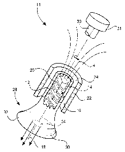
Fig. 2 shows a more concrete exemplary embodiment of the apparatus 11. In this
arrangement a cooling element 12 is designed as a hollow cylinder through
which the gas 4
to be dried flows. With adequate cooling, the first surface 14, designed as an
inside surface
CA 02781710 2012-05-23
- 9 -
of the cooling element, is covered by ice, and the gas 4 is dried as it flows
through the
cooling element 12. To remove the ice layer on the first surface 14 a
detachment device 16
is used that is rotatably held on an axis 18, wherein the axis 18 corresponds
to the axis of
extension of the cooling element 12 and consequently is arranged
concentrically to the
aforesaid. The drive of the detachment device 16 is implemented by a
diagrammatically
shown drive device 31 which by way of a shaft 33 is connected with the
detachment device
16, wherein the shaft 33 extends over a greater height than does the cooling
element 12, and
consequently the inflow of the gas 4 to be dried is made possible.
In this arrangement the detachment device 16 comprises a spiral-shaped or
helical edge 20
that continuously scrapes along the first surface 14 of the cooling element 12
when the
detachment device 16 is rotating. In this manner continuous detachment of ice
from the first
surface 14 is carried out.
Preferably, the detachment device 16 comprises a helical turn arrangement that
is
sufficiently coarse to allow easy flow of the gas 4 through the apparatus,
while at the same
time, however, ice detachment can remain assured.
In the exemplary embodiment shown, the hollow-cylindrically-shaped cooling
element 12 is
enclosed by a further cylindrically-shaped body 22 that defines a gap 24 to
the cooling
element 12. A cooling medium could flow through this gap 24, which cooling
medium by
passing along a second surface 26 of the cooling element 12 results in cooling
as a result of
which the water content of the gas 4 freezes on the first surface 14.
A lower region 28 of the cooling element 12 comprises an outward-expanding
shape which,
for example as a reservoir, provides sufficient space for accumulated ice that
has been
detached from the first surface 14. Optionally, a corresponding aperture 30
can be provided
through which the ice, or ice in the form of meltwater, which ice has been
melted by
exposure to external heat, is discharged. The outward-formed region 28 of the
cooling
element 12 could comprise a cover 32 that in the extension of the axis 18
comprises a cutout
34 that allows unimpeded flowing out of the gas 4.
CA 02781710 2012-05-23
- 10 -
Fig. 3a diagrammatically shows apparatus 11, which apparatus is connected with
a
cryogenic hydrogen tank 35 filled with liquid hydrogen. Liquid hydrogen enters
the gap 24,
cools the cooling element 12, and is returned to the tank 35 or is conveyed
for use in a fuel
cell or the like.
Fig. 3b diagrammatically shows a heat exchanger 37 that is cooled by ambient
air 39. A
separate cooling circuit 41 connects the heat exchanger 37 with the apparatus
so that direct
introduction of ambient air can be prevented. After use in the heat exchanger
37 the ambient
air 39 can be removed. As an alternative to this, in the apparatus ambient air
can also flow
directly through the gap 24.
Furthermore, Fig. 4 shows the essential steps of the method according to the
invention. In
the first instance a first surface of a cooling element is subjected 36 to a
gas stream to be
dried; by way of a thermal connection with a heat sink the cooling element is
cooled 38 in
order to, in this process, freeze the water vapor or water content contained
in the gas so that
the ice accumulates on the first surface. At the same time, subsequently or
alternatingly, a
detachment device on the first surface is moved 40 so that the ice that has
accumulated on
the first surface is removed. Optionally, removed ice is collected in a
reservoir, and,
furthermore optionally, is melted 42 by exposure to external heat. The ice
collected in the
reservoir can fall out of it or can be discharged 44 from it; likewise the ice
that has
optionally been melted by exposure to heat can be channeled out.
Finally, Fig. 5 shows an aircraft 46 comprising at least one fuel cell system
48 that feeds into
fuel tanks 52 an exhaust gas containing water vapor through apparatus 50 in a
dried state for
rendering inert said fuel tanks 52.
In addition, it should be pointed out that "comprising" does not exclude other
elements or
steps, and "a" or "one" does not exclude a plural number. Furthermore, it
should be pointed
out that characteristics or steps which have been described with reference to
one of the
above exemplary embodiments can also be used in combination with other
characteristics or
steps of other exemplary embodiments described above. Reference characters in
the claims
are not to be interpreted as limitations.
CA 02781710 2012-05-23
- 11 -
LIST OF REFERENCE CHARACTERS
2 Cooling element
4 Gas
6 First surface
8 Detachment device
Scraping edge
11 Apparatus
12 Cooling element
10 14 First surface
16 Detachment device
18 Axis
Edge
22 Body
15 24 Gap
26 Second surface
28 Outwardly formed region
Aperture
31 Drive device
20 32 Cover
33 Shaft
34 Cutout
Cryogenic hydrogen tank
36 Subject to gas flow
25 37 Heat exchanger
38 Cooling the cooling element
39 Ambient air
First surface
41 Separate cooling circuit
30 42 Melt
44 Discharge
46 Aircraft
CA 02781710 2012-05-23
- 12 -
48 Fuel cell system
50 Apparatus
52 Fuel tank