Note : Les descriptions sont présentées dans la langue officielle dans laquelle elles ont été soumises.
CA 02781882 2012-05-25
WO 2010/063013 PCT/US2009/066025
ADAPTIVE, LOW-IMPACT VEHICLE ENERGY HARVESTER
CROSS-REFERENCE TO RELATED APPLICATIONS
[0001] The present invention claims the benefit of U.S. Provisional Patent
Application No. 61/118,339, filed November 26, 2008, and entitled "ADAPTIVE,
LOW-IMPACT VEHICLE ENERGY HARVESTER", and U.S. Provisional Patent
Application No. 61/118,334, filed November 26, 2008, and entitled "ADAPTIVE
VEHICLE ENERGY HARVESTER", the entire contents of which are incorporated
herein by reference in their entirety.
FIELD OF THE INVENTION
[0002] The present invention is directed toward devices and methods of
harvesting vehicle energy, and more specifically, toward an adaptive, low-
impact
vehicle energy harvester and a methods of adaptively harvesting vehicle
energy.
BACKGROUND OF THE INVENTION
[0003] Very few devices that capture energy from passing vehicles have been
implemented, despite numerous designs put forth by various parties over the
years.
Issues of efficiency, reliability, and manufacturability, among others, have
limited the
practicality of vehicle energy harvesting devices. Added to the challenge is
the
variability of vehicle sizes, speeds, axle configurations, and lane positions,
all of
which can greatly influence the operation of a device trying to capture energy
from
vehicles and convert it into a useful form of power.
[0004] Therefore, a need exists for an energy capture device and method
having improved efficiency, reliability, and manufacturability, as well as
practicality.
1
CA 02781882 2012-05-25
WO 2010/063013 PCT/US2009/066025
A need also exists for an energy capture device and method that takes into
account
the variability of vehicle sizes, speeds, axle configurations, and/or lane
positions in
converting vehicle energy into a useful form of power.
SUMMARY OF THE INVENTION
[0005] These problems and others are addressed by the present invention,
which provides a novel vehicle energy harvester that overcomes many of the
issues
with the conventional devices and is therefore better suited for real-world
implementation than the conventional art.
[0006] An exemplary embodiment of the invention is directed to a system for
converting energy of a moving vehicle into a useful form, the system
comprising one
or more compressible, elongated hollow bodies configured to be disposed
longitudinally on or in a trafficway such that a movement of a vehicle along
said
trafficway causes contents in said elongated hollow bodies to be expelled from
one
end; a motor in communication with said hollow bodies such that said contents
expelled from one end of said hollow bodies actuates said motor; a control
unit that
varies a resistance to the movement of said contents in said elongated hollow
bodies
based on at least one of: i. a mass of the vehicle, ii. a velocity of the
vehicle, and iii. a
rate of change of velocity of the vehicle.
[0007] An exemplary embodiment of the invention is directed to a method of
converting energy of a moving vehicle into a useful form, the method
comprising
actuating a motor, which is in communication with a compressible, elongated
hollow
body disposed on or in a trafficway, using contents expelled from one end of
said
compressible, elongated hollow body by a movement of a vehicle along the
trafficway; and varying a resistance to the movement of said contents in said
2
CA 02781882 2012-05-25
WO 2010/063013 PCT/US2009/066025
compressible, elongated hollow body based on at least one of: i. a mass of the
vehicle, ii. a velocity of the vehicle, and iii. a rate of change of velocity
of the
vehicle.
[0008] An exemplary embodiment of the invention is directed to a system for
converting energy of a moving vehicle into a useful form, the system
comprising: a.
one or more compressible, elongated hollow bodies configured to be disposed
longitudinally on or in a trafficway such that a movement of a vehicle along
said
trafficway causes contents in said elongated hollow bodies to be expelled from
one
end; b. a motor in communication with said hollow bodies such that said
contents
expelled from one end of said hollow bodies actuates said motor; and c. one or
more
means for varying a resistance to the movement of said contents in said
elongated
hollow bodies based on at least one of: i. a mass of the vehicle, ii. a
velocity of the
vehicle, and iii. a rate of change of velocity of the vehicle.
[0009] An exemplary embodiment of the invention is directed to a system for
converting the energy of a moving vehicle into a useful form, wherein the
interaction
of a moving vehicle with a means for capturing energy causes a flow through
said
means for capturing energy, and said flow is retarded by a variable amount at
least
in part according to at least one of: i. a mass of the vehicle, ii. a velocity
of the
vehicle, and iii. a rate of change of velocity of the vehicle.
[0010] An exemplary embodiment of the invention is directed to a system for
converting energy of a moving vehicle into a useful form, wherein an
interaction of a
moving vehicle with a device for capturing energy causes a flow through said
device
for capturing energy, and said flow is retarded by a variable amount at least
in part
according to at least one of: i. a mass of the vehicle, ii. a velocity of the
vehicle, and
iii. a rate of change of velocity of the vehicle.
3
CA 02781882 2012-05-25
WO 2010/063013 PCT/US2009/066025
[0011] An exemplary embodiment of the invention is directed to a method of
converting the energy of a moving vehicle into a useful form, the method
comprising
causing a flow through an energy capture device based on an interaction of a
moving vehicle with the energy capture device, wherein the flow is retarded by
a
variable amount at least in part according to at least one of: i. a mass of
the vehicle,
ii. a velocity of the vehicle, and iii. a rate of change of velocity of the
vehicle.
[0012] An exemplary embodiment of the invention is directed to a system for
converting energy of a moving vehicle into a useful form, the system
comprising: a.
two channels disposed longitudinally in a trafficway, each containing one or
more
compressible, elongated hollow bodies such that the movement of a vehicle
along
said trafficway causes contents in said elongated hollow bodies to be expelled
from
one end; b. a motor in communication with said hollow bodies such that said
contents expelled from said hollow bodies actuates said motor; c. one or more
means of measuring directly or indirectly at least one of: i. a mass of the
vehicle, ii. a
velocity of the vehicle, and iii. a rate of change of velocity of the vehicle;
and d. one
or more means for varying a resistance to the movement of said contents in
said
elongated hollow bodies based on said means of measuring.
[0013] An exemplary embodiment of the invention is directed to a system for
converting the energy of a moving vehicle into a useful form, wherein the
interaction
of a moving vehicle with a means for capturing energy causes a flow through
said
means for capturing energy, and said flow is retarded by a variable amount at
least
in part according to one or more means of measuring directly or indirectly at
least
one of: i. a mass of the vehicle, ii. a velocity of the vehicle, and iii. a
rate of change of
velocity of the vehicle.
4
CA 02781882 2012-05-25
WO 2010/063013 PCT/US2009/066025
[0014] An exemplary embodiment of the invention is directed to a system for
converting energy of a moving vehicle into a useful form, the system
comprising: a
plurality of channels disposed longitudinally on or in a trafficway, wherein
each of the
plurality of channels includes one or more compressible, elongated hollow
bodies
such that a movement of a vehicle along said trafficway causes contents in
said
elongated hollow bodies to be expelled from one end; a motor in communication
with
said hollow bodies such that said contents expelled from one end of said
hollow
bodies actuates said motor; a first unit that measures directly or indirectly
at least
one of: i. a mass of the vehicle, ii. a velocity of the vehicle, and iii. a
rate of change of
velocity of the vehicle; and a second unit that varies a resistance to the
movement of
said contents in said elongated hollow bodies based on measurements by said
first
unit.
[0015] An exemplary embodiment of the invention is directed to a method of
converting energy of a moving vehicle into a useful form, the method
comprising:
actuating a motor, which is in communication with a compressible, elongated
hollow
body disposed on or in a trafficway, using contents expelled from one end of
said
compressible, elongated hollow body by a movement of a vehicle along the
trafficway; measuring directly or indirectly at least one of: i. a mass of the
vehicle, ii.
a velocity of the vehicle, and iii. a rate of change of velocity of the
vehicle; and
varying a resistance to the movement of said contents in said compressible,
elongated hollow body based on the measuring.
[0016] An exemplary embodiment of the invention is directed to a system for
converting energy of a moving vehicle into a useful form, wherein an
interaction of a
moving vehicle with a device for capturing energy causes a flow through said
device
for capturing energy, and said flow is retarded by a variable amount at least
in part
CA 02781882 2012-05-25
WO 2010/063013 PCT/US2009/066025
according to a measuring unit that measures directly or indirectly at least
one of: i. a
mass of the vehicle, ii. a velocity of the vehicle, and iii. a rate of change
of velocity of
the vehicle.
[0017] An exemplary embodiment of the invention is directed to a method of
converting the energy of a moving vehicle into a useful form, the method
comprising:
causing a flow through a energy capturing device based on an interaction of a
moving vehicle with the energy capturing device, wherein the flow is retarded
by a
variable amount at least in part according to one or more means of measuring
directly or indirectly at least one of: i. a mass of the vehicle, ii. a
velocity of the
vehicle, and iii. a rate of change of velocity of the vehicle.
BRIEF DESCRIPTION OF THE DRAWINGS
[0018] These and other aspects and features of embodiments of the present
invention will be better understood after a reading of the following detailed
description, together with the attached drawings, wherein:
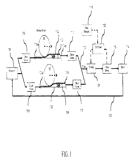
[0019] Figure 1 is a schematic illustrating a vehicle energy harvester
according to an exemplary embodiment of the invention.
[0020] Figure 2 is a schematic illustrating a vehicle energy harvester
according to another exemplary embodiment of the invention.
[0021] Figure 3 is a schematic illustrating a vehicle energy harvester
according to another exemplary embodiment of the invention.
DETAILED DESCRIPTION
[0022] The present invention now is described more fully hereinafter with
reference to the accompanying drawings, in which embodiments of the invention
are
6
CA 02781882 2012-05-25
WO 2010/063013 PCT/US2009/066025
shown. This invention may, however, be embodied in many different forms and
should not be construed as limited to the embodiments set forth herein;
rather, these
embodiments are provided so that this disclosure will be thorough and
complete, and
will fully convey the scope of the invention to those skilled in the art.
[0023] Referring now to the drawings, FIGS. 1-3 illustrate exemplary
embodiments of a vehicle energy harvester.
[0024] With reference to Figures 1-3, an exemplary embodiment of the vehicle
energy harvester 100 includes two channels 102 disposed longitudinally in a
roadway that contain a number of resilient hydraulic lines 104. The channels
102 can
be deep enough that a resilient, durable cover may be placed over each set of
lines
104 and have a top surface just below the surface of the greater roadway.
Dividing
the hydraulic lines 104 into two sets near either edge of a lane minimizes the
contact
area between the resilient, durable cover and potentially damaging road
equipment
such as street cleaners and snow plows. Instead, a conventional pavement
surface
between the channels largely supports those equipment loads. The lines 104 are
connected to a pressurized fluid reservoir 106 through check valves 108 at the
line
inlets 104a. Another set of check valves 110 at the line outlets 104b connect
the
lines 104 to a fluid manifold 112 with a single outlet 112a. The outlet 112a
communicates with a hydraulic motor 114. The outlet 112a may also communicate
with an inline flow meter 116 or other sensors 118. A hydraulic line 120
provides a
return from the hydraulic motor 114 to the fluid reservoir 106.
[0025] During operation of an embodiment, each wheel W on a vehicle of
appropriate size will depress the resilient cover and collapse a portion of
hydraulic
lines 104 underneath. As each wheel W continues to roll along, a volume of
fluid in
the line 104 will be forced to flow along the line 104 and towards the
hydraulic motor
7
CA 02781882 2012-05-25
WO 2010/063013 PCT/US2009/066025
114. The interaction between wheel W and resilient cover will impart a
reaction force
on the wheel W, which will have a horizontal component that will act to slow
the
wheel's translation. As forces act on each of the wheels W, the vehicle as a
whole
will slow down, corresponding to the energy that has been drawn from the
vehicle by
the energy harvesting device. The energy transferred to the flowing
pressurized fluid
may be stored in an accumulator (not shown) for later use or converted through
the
hydraulic motor 114 to another form such as electricity.
[0026] In another embodiment, the vehicle energy harvester 100 can adjust
the reaction force imparted on an incident vehicle in response to the motion
characteristics of that vehicle.
[0027] For example, the energy harvester 100 may include a flow meter 116
at the outlet 112a of hydraulic line manifold 112, as shown in Figures 2 and
3. The
vehicle energy harvester 100 can monitor this flow meter 116 over time and,
from it,
approximate the speed and acceleration or deceleration of a vehicle as it
interacts
with the vehicle energy harvester 100, for example, using controller 122. If a
vehicle
is massive enough that its reaction force with the energy harvester 100 slows
the
vehicle far less than it safely could, the vehicle energy harvester 100 may
increase
its resistance to the vehicle's motion until it reaches an operational or
safety limit.
Similarly, if a less massive vehicle encounters the energy harvester 100 and
begins
to decelerate too quickly, the energy harvester 100 may decrease the
resistance
presented to the vehicle. In one embodiment, the vehicle energy harvester 100
resistance is varied using a throttle 124 that restricts fluid flow from the
resilient lines
104 by an adjustable amount.
[0028] In another embodiment, for example, as illustrated in Figure 3, the
hydraulic motor 114 is connected to a separately-excited generator 126 with
torque
8
CA 02781882 2012-05-25
WO 2010/063013 PCT/US2009/066025
control 128. The vehicle energy harvester 100 adjusts the back torque of the
generator 126 in response to the flow meter 116 or other signals, which alters
fluid
flow through the hydraulic motor 114 and thereby varies the reacting force
against
the wheels W of a vehicle.
[0029] In another embodiment, for example, as illustrated in Figure 2, a
generator 126 is coupled to the hydraulic motor 114 through a continuously
variable
transmission (CVT) (not shown). Higher CVT ratios cause the generator 126 to
spin
faster for a given flow rate in the resilient tubes 104, producing more back
torque to
resist the flow of fluid through the tubes 104. The energy harvester 100 may
vary the
CVT ratio, and therefore harvester resistance to motion, based on measures
such as
flow rate or direct vehicle speed or mass. Alternatively, the vehicle energy
harvester
100 may vary generator speed per flow rate by altering a variable displacement
hydraulic pump that drives the generator 126.
[0030] In another exemplary embodiment, if the energy harvester's resistance
to vehicle motion becomes sufficient, one or more vehicle wheels W may climb
their
corresponding depressions in their resilient tubes 104 and cease to transfer
meaningful energy to the harvesting device 100. In that case, the energy
harvester
100 may sense a diminished flow rate and reduce the resistance to fluid flow
until the
wheels W depress the tubes 104 once more and fluid flow rate increases to an
appropriate amount.
[0031] In applications where safe speed regulation may be a concern, the
vehicle energy harvester 100 can adjust its resistance to help ensure that a
vehicle
departs the device at a safe speed. In such cases, the vehicle energy
harvester 100
may use measures like flow rate to determine the necessary deceleration
required to
9
CA 02781882 2012-05-25
WO 2010/063013 PCT/US2009/066025
slow a vehicle to a target speed. That deceleration may be limited to a
configurable
value deemed safe for the vehicle and its occupants.
[0032] The exemplary embodiments provide advantages beyond its potential
adaptability. Whereas many conventional vehicle energy harvesters employ a
number of interaction points between vehicle and device, exemplary embodiments
of
the present invention interact continuously with a vehicle during the period
of energy
capture and conversion. The principal benefit is that with the embodiments of
the
present invention, a vehicle is not subject to repeated impact events that
could
disrupt the comfort of an operator or their control over their vehicle.
Moreover, the
vehicle energy harvester 100 can gradually capture the energy of a vehicle
over an
extended period, converting more energy into useful power than devices that
rely on
a series of brief vehicle-device interactions.
[0033] As described, an exemplary embodiment requires no above-surface
structures in the roadway, which not only reduces the risk to small vehicles
such as
motorcycles but also minimizes the likelihood that drivers will react to the
system by
applying their brakes or attempting evasive maneuvers. Furthermore, another
exemplary embodiment provides a closed, sealed system, making it far more
impervious to road debris, ice, snow, etc.
[0034] For example, an exemplary embodiment is directed to a system for
converting the energy of a moving vehicle into a useful form, comprising:
[0035] a. two channels 102 disposed longitudinally in a trafficway, each
containing one or more compressible, elongated hollow bodies 104 such that the
movement of a vehicle along said trafficway causes the contents in said
elongated
hollow bodies 104 to be expelled from one end,
CA 02781882 2012-05-25
WO 2010/063013 PCT/US2009/066025
[0036] b. a motor 114 in communication with said hollow bodies 104 such
that said contents expelled from one end of said hollow bodies 104 actuates
said
motor 114,
[0037] c. one or more means (e.g., throttle 124, flow meter 116, controller
122, and/or other sensors 118; flow meter 116, motor 114, generator 126,
controller
122, and/or other sensors 118; or flow meter 116, motor 114, generator 126,
torque
control 128, controller 122, and/or other sensors 118) for varying a
resistance to the
movement of said contents in said elongated hollow bodies 104 based on:
i. a mass of the vehicle,
ii. a velocity (or speed) of the vehicle, and
iii. a rate of change of velocity of the vehicle (i.e.,
acceleration or deceleration).
[0038] Another exemplary embodiment is directed to a means (e.g., 100) for
converting the energy of a moving vehicle into a useful form, wherein the
interaction
of a moving vehicle with a means for capturing energy causes a flow through
said
means for capturing energy, and said flow is retarded by a variable amount at
least
in part according to at least one of:
i. a mass of the vehicle,
ii. a velocity (or speed) of the vehicle, and
iii. a rate of change of velocity of the vehicle.
[0039] The embodiments provide an energy capture device 100 and method
having improved efficiency, reliability, and manufacturability, as well as
practicality.
The exemplary energy capture device 100 and method takes into account the
variability of vehicle sizes, speeds, axle configurations, and lane positions
in
converting the captured motion energy of vehicles into a useful form of
energy.
11
CA 02781882 2012-05-25
WO 2010/063013 PCT/US2009/066025
[0040] In some exemplary embodiments, the vehicle energy harvester 100 or
harvester controller 122 may determine or calculate one or more of, for
example, the
speed or velocity of a vehicle, the rate of change of velocity over time
(i.e., the
acceleration or deceleration) of a vehicle, the direct or indirect measure of
a mass of
a vehicle, etc. In other exemplary embodiments, the vehicle energy harvester
100 or
harvester controller 122 may receive as an input one or more of, for example,
the
speed or velocity of a vehicle, the acceleration or deceleration of a vehicle,
the direct
or indirect measure of a mass of a vehicle, etc., for example, from other
sensors 118.
These sensors 118 can include one or more conventional sensors for detecting
the
speed or velocity of a vehicle, the acceleration or deceleration of a vehicle,
the direct
or indirect measure of a mass of a vehicle, etc.
[0041] Another exemplary embodiment is directed to a system for converting
the energy of a moving vehicle into a useful form, comprising:
[0042] a. two channels 102 disposed longitudinally in a trafficway, each
containing one or more compressible, elongated hollow bodies 104 such that the
movement of a vehicle along said trafficway causes the contents in said
elongated
hollow bodies 104 to be expelled from one end,
[0043] b. a motor 114 in communication with said hollow bodies 104 such
that said contents expelled from one end of said hollow bodies 104 actuates
said
motor 114,
[0044] c. one or more means (e.g., other sensors 118) of measuring
directly or indirectly at least one of:
i. a mass of the vehicle,
ii. a velocity (or speed) of the vehicle, and
iii. a rate of change of velocity of the vehicle, and
12
CA 02781882 2012-05-25
WO 2010/063013 PCT/US2009/066025
[0045] d. one or more means (e.g., throttle 124, flow meter 116, and/or
controller 122; flow meter 116, motor 114, generator 126, and/or controller
122; or
flow meter 116, motor 114, generator 126, torque control 128, and/or
controller 122)
for varying a resistance to the movement of said contents in said elongated
hollow
bodies 104 based on said means of measuring.
[0046] Another exemplary embodiment is directed to a means (e.g., 100) for
converting the energy of a moving vehicle into a useful form, wherein the
interaction
of a moving vehicle with the means for capturing energy causes a flow through
said
means for capturing energy, and said flow is restricted by a variable amount
at least
in part according to one or more means (e.g., other sensors 118) of measuring
directly or indirectly at least one of:
i. a mass of the vehicle,
ii. a velocity of the vehicle, and
iii. a rate of change of velocity of the vehicle.
[0047] The embodiments provide an energy capture device and method
having improved efficiency, reliability, and manufacturability, as well as
practicality.
The exemplary energy capture device and method takes into account the
variability
of vehicle sizes, speeds, axle configurations, and lane positions in
converting the
captured motion energy of vehicles into a useful form of energy. The
embodiments
of the present invention also provide an ability to monitor or regulate the
speed of
moving vehicles.
[0048] The present invention has been described herein in terms of several
preferred embodiments. However, modifications and additions to these
embodiments will become apparent to those of ordinary skill in the art upon a
reading of the foregoing description. It is intended that all such
modifications and
13
CA 02781882 2012-05-25
WO 2010/063013 PCT/US2009/066025
additions comprise a part of the present invention to the extent that they
fall within
the scope of the several claims appended hereto.
[0049] Like numbers refer to like elements throughout. In the figures, the
thickness of certain lines, layers, components, elements or features may be
exaggerated for clarity.
[0050] The terminology used herein is for the purpose of describing particular
embodiments only and is not intended to be limiting of the invention. Unless
otherwise defined, all terms (including technical and scientific terms) used
herein
have the same meaning as commonly understood by one of ordinary skill in the
art
to which this invention belongs. It will be further understood that terms,
such as
those defined in commonly used dictionaries, should be interpreted as having a
meaning that is consistent with their meaning in the context of the
specification and
relevant art and should not be interpreted in an idealized or overly formal
sense
unless expressly so defined herein. Well-known functions or constructions may
not
be described in detail for brevity and/or clarity.
[0051] As used herein, the singular forms "a", "an" and "the" are intended to
include the plural forms as well, unless the context clearly indicates
otherwise. It will
be further understood that the terms "comprises" and/or "comprising," when
used in
this specification, specify the presence of stated features, integers, steps,
operations, elements, and/or components, but do not preclude the presence or
addition of one or more other features, integers, steps, operations, elements,
components, and/or groups thereof. As used herein, the term "and/or" includes
any
and all combinations of one or more of the associated listed items. As used
herein,
phrases such as "between X and Y" and "between about X and Y" should be
interpreted to include X and Y. As used herein, phrases such as "between about
X
14
CA 02781882 2012-05-25
WO 2010/063013 PCT/US2009/066025
and Y" mean "between about X and about Y." As used herein, phrases such as
"from
about X to Y" mean "from about X to about Y."
[0052] It will be understood that when an element is referred to as being
"on",
"attached" to, "connected" to, "coupled" with, "contacting", etc., another
element, it
can be directly on, attached to, connected to, coupled with or contacting the
other
element or intervening elements may also be present. In contrast, when an
element
is referred to as being, for example, "directly on", "directly attached" to,
"directly
connected" to, "directly coupled" with or "directly contacting" another
element, there
are no intervening elements present. It will also be appreciated by those of
skill in
the art that references to a structure or feature that is disposed "adjacent"
another
feature may have portions that overlap or underlie the adjacent feature.
[0053] Spatially relative terms, such as "under", "below", "lower", "over",
"upper", "lateral", "left", "right" and the like, may be used herein for ease
of
description to describe one element or feature's relationship to another
element(s) or
feature(s) as illustrated in the figures. It will be understood that the
spatially relative
terms are intended to encompass different orientations of the device in use or
operation in addition to the orientation depicted in the figures. For example,
if the
device in the figures is inverted, elements described as "under" or "beneath"
other
elements or features would then be oriented "over" the other elements or
features.
The device may be otherwise oriented (rotated 90 degrees or at other
orientations)
and the descriptors of relative spatial relationships used herein interpreted
accordingly.
[0054] Further, many embodiments are described in terms of sequences of
actions to be performed by, for example, elements of a computing device. It
will be
recognized that various actions described herein can be performed by specific
CA 02781882 2012-05-25
WO 2010/063013 PCT/US2009/066025
circuits (e.g., application specific integrated circuits (ASICs)), by program
instructions
being executed by one or more processors, or by a combination of both.
Additionally, these sequence of actions described herein can be considered to
be
embodied entirely within any form of computer readable storage medium having
stored therein a corresponding set of computer instructions that upon
execution
would cause an associated processor to perform the functionality described
herein.
Thus, the various aspects of the invention may be embodied in a number of
different
forms, all of which have been contemplated to be within the scope of the
claimed
subject matter. In addition, for each of the embodiments described herein, the
corresponding form of any such embodiments may be described herein as, for
example, "logic configured to" perform the described action.
[0055] Those of skill in the art will appreciate that information and signals
may
be represented using any of a variety of different technologies and
techniques. For
example, data, instructions, commands, information, signals, bits, symbols,
and
chips that may be referenced throughout the above description may be
represented
by voltages, currents, electromagnetic waves, magnetic fields or particles,
optical
fields or particles, or any combination thereof.
[0056] Further, those of skill in the art will appreciate that the various
illustrative logical blocks, modules, circuits, and algorithm steps described
in
connection with the embodiments disclosed herein may be implemented as
electronic hardware, computer software, or combinations of both. To clearly
illustrate this interchangeability of hardware and software, various
illustrative
components, blocks, modules, circuits, and steps have been described above
generally in terms of their functionality. Whether such functionality is
implemented
as hardware or software depends upon the particular application and design
16
CA 02781882 2012-05-25
WO 2010/063013 PCT/US2009/066025
constraints imposed on the overall system. Skilled artisans may implement the
described functionality in varying ways for each particular application, but
such
implementation decisions should not be interpreted as causing a departure from
the
scope of the present invention.
[0057] The methods, sequences and/or algorithms described in connection
with the embodiments disclosed herein may be embodied directly in hardware, in
a
software module executed by a processor, or in a combination of the two. A
software module may reside in RAM memory, flash memory, ROM memory, EPROM
memory, EEPROM memory, registers, hard disk, a removable disk, a CD-ROM, or
any other form of storage medium known in the art. An exemplary storage medium
is coupled to the processor such that the processor can read information from,
and
write information to, the storage medium. In the alternative, the storage
medium
may be integral to the processor.
[0058] Accordingly, an embodiment of the invention can include a computer
readable media embodying a method for controlling the measuring, either
directly or
indirectly, of at least one of a mass of the vehicle, a velocity of the
vehicle, and a rate
of change of velocity of the vehicle; and varying a resistance to a movement
of the
contents in the compressible, elongated hollow body based on the measuring.
Accordingly, the invention is not limited to illustrated examples and any
means for
performing the functionality described herein are included in embodiments of
the
invention.
[0059] While the foregoing disclosure shows illustrative embodiments of the
invention, it should be noted that various changes and modifications could be
made
herein without departing from the scope of the invention as defined by the
appended
claims. The functions, steps and/or actions of the method claims in accordance
with
17
CA 02781882 2012-05-25
WO 2010/063013 PCT/US2009/066025
the embodiments of the invention described herein need not be performed in any
particular order. Furthermore, although elements of the invention may be
described
or claimed in the singular, the plural is contemplated unless limitation to
the singular
is explicitly stated.
18