Note : Les descriptions sont présentées dans la langue officielle dans laquelle elles ont été soumises.
CA 027821412012-05-28
WO 2011/079190
PCT/US2010/061772
Dynamic Load Estimation of Multiple Branch Circuits
Background of the Invention
1. Field of Invention
[0001] Embodiments of the present invention relate generally to circuit
load
characteristics, and more specifically, to estimating energy usage of branch
circuits of
an electrical distribution panel.
2. Discussion of Related Art
[0002] Electrical equipment consumes energy, and different types of
electrical
equipment have different energy requirements. Knowledge of the amount of
energy
used by different types of electrical equipment facilitates efficient power
distribution
and billing for consumed power and other power management operations.
[0003] Determining the energy consumption of a load generally requires
direct
and individual power measurements of that load. Distributed power meters
individually register power consumption of different loads, even when the
power to
each load originates from a common power source. For example, a main power
source supplies power to an apartment complex, and separate power meters
register
the power consumption of each apartment for billing or other purposes. This
generally requires a dedicated power meter for each apartment, which is costly
and
inefficient, and requires redundant infrastructure elements throughout a power
distribution system.
[0004] United States Patent Application Publication US 2008/0278344 to
Bardehle, et al. relates to a method and arrangement for registering and
evaluating
energy consumption. Bardehle discloses buildings such as hotels that have a
1091476.1 1
CA 027821412012-05-28
WO 2011/079190
PCT/US2010/061772
building-wide data bus as part of an energy management system. This data bus
makes
it possible to register the switched-on duration of individual loads such as
the lighting
or heating system of individual hotel rooms. The energy consumption of a
particular
hotel room is then determined by multiplying the registered on-time of the
individual
loads by the specific electrical power or energy consumption of the load.
However,
this requires advance knowledge of the specific electrical power of the load,
such as
the wattage ratings of the lighting devices in a particular hotel room, in
order to
evaluate energy consumption.
Summary of the Invention
[0005] There is a need for the systems and methods described herein that
provide individual branch circuit energy usage based on a main line power
estimation
and not individual branch circuit power measurements. As discussed herein,
power
usage of an electrical distribution panel main line is determined with a
plurality of
branch circuits coupled to the main line and again with one of the plurality
of branch
circuits decoupled from the main line. The energy usage of individual branch
circuits
is estimated based at least in part on the difference between the power usage
of the
panel with that branch circuit coupled and decoupled to the main line. These
systems
and methods estimate branch circuit energy usage based on main line power
measurements during different panel states of operation without individual
direct
branch circuit power or current measurements, and without advance knowledge of
branch circuit load characteristics.
[0006] In some embodiments, a main line couples a power source with a
plurality of branch circuits of an electrical distribution panel. The total
power usage
of the main line is determined with at least two of the plurality of branch
circuits
coupled to the main line, and a first power usage of the main line is
determined when
a first of the at least two branch circuits is decoupled from the main line. A
first time
period that the first branch circuits is coupled from the main line is
identified, and the
2
CA 027821412012-05-28
WO 2011/079190
PCT/US2010/061772
energy usage of the first branch circuit is estimated based on the first time
period and
a differential between the total power usage and the first power usage.
[0007] One aspect is directed to a method of estimating energy provided to
a
load. The method includes an act of determining a total power usage of a main
line of
an electrical distribution panel. The electrical distribution panel has a
plurality of
branch circuits with at least two of the plurality of branch circuits coupled
to the main
line. The method also includes acts of determining a first power usage of the
main
line with a first of the two branch circuits decoupled from the main line, and
identifying a first time period that the first branch circuit is coupled with
the main
line. A kilowatt-hour energy usage value of the first branch circuit is
estimated based
on the first time period and a differential between the total power usage and
the first
power usage.
[0008] One other aspect is directed to a branch circuit load estimation
system.
The system includes an electrical distribution panel with a plurality of
branch circuits,
and a power sensor. The power sensor determines total power usage of a main
line of
the electrical distribution panel during operation with at least two of the
plurality of
branch circuits coupled to the main line. The power sensor also determines a
first
power usage of the main line with a first of the two branch circuits decoupled
from
the main line. A controller determines a first time period that the first
branch circuit
is coupled with the main line, and estimates a kilowatt-hour energy usage
value of the
first branch circuit based on the first time period and a differential between
the total
power usage and the first power usage.
[0009] One other aspect is directed to a branch circuit load estimation
system.
The system includes an electrical distribution panel having a plurality of
branch
circuits and a power sensor. The power sensor determines total power usage of
a
main line of the electrical distribution panel during operation with at least
two of the
plurality of branch circuits coupled to the main line. The power sensor also
determines a first power usage of the main line with a first of the two branch
circuits
3
CA 027821412012-05-28
WO 2011/079190
PCT/US2010/061772
decoupled from the main line. A controller determines a first time period that
the first
branch circuit is coupled with the main line. The system also includes means
for
estimating a kilowatt-hour energy usage value of the first branch circuit
based on the
first time period and a differential between the total power usage and the
first power
usage.
[0010] In some embodiments, a decoupling of the first branch circuit from
the
main line is detected, and the first power usage is determined with a second
of the two
branch circuits coupled with the main line. In one embodiment, a state change
of the
first branch circuit from an ON state to an OFF state is detected and the
first power
usage is determined with the first branch circuit in the OFF state. A second
kilowatt-
hour energy usage value of the first branch circuit can be estimated during a
second
time period based on the first time period and a differential between the
total power
usage and the first power usage. In one embodiment, the second kilowatt-hour
energy
usage value is averaged with a previous estimated kilowatt-hour energy usage
value
of the first branch circuit, wherein the previous estimated kilowatt-hour
energy usage
value consists of estimated kilowatt-hour energy usage value of the first
branch circuit
during a third time period that occurs prior to the second time period.
[0011] In one embodiment, the total power usage is determined by metering a
current of the main line with the at least two of the plurality of branch
circuits coupled
with the main line, and calculating the total power usage based on the current
and a
voltage corresponding to the current. The fist power usage can also be
determined by
metering a current of the main line with the first branch circuit decoupled
from the
main line and calculating the first power usage based on the current and a
voltage
corresponding to the current.
[0012] In some embodiments, the total power usage of the main line is
determined with each of the plurality of branch circuits coupled
simultaneously with
the main line, and the first power usage is determined with the first branch
circuit
decoupled from the main line and with each of the plurality of branch circuits
except
4
for the first branch circuit coupled with the main line. In one embodiment a
plurality
of states of the electrical distribution panel is identified, where each state
consists of
one branch circuit of the plurality of branch circuits that is decoupled from
the main
line and one coupled branch circuit of the plurality of branch circuits that
is coupled
with the main line. The total power usage of the main line for at least two of
the
plurality of states, and, for the at least two states, a kilowatt-hour energy
usage value
of the one branch circuit that is decoupled from the main line during each of
the at
least two states is estimated.
[0013] In one embodiment, a first cycle that includes a plurality of
states of
the electrical distribution panel is identified, where each state consists of
one branch
circuit of the plurality of branch circuits that is decoupled from the main
line and one
coupled branch circuit of the plurality of branch circuits that is coupled
with the main
line. The total power usage of the main line can be determined at each of the
plurality
of states of the first cycle, and, for a first state of the first cycle, a
kilowatt-hour
energy usage value of the one branch circuit that is decoupled from the main
line
during the first state is estimated and averaged with a kilowatt-hour energy
usage
value of the one branch circuit corresponding to a state of a second cycle of
a plurality
of second states.
One other aspect provides a method of estimating energy provided to a
load, comprising: measuring, at a main line of an electrical distribution
panel having a
plurality of branch circuits, a total power usage of the main line during a
first time
period with at least two of the plurality of branch circuits coupled to the
main line;
measuring, at the main line, a first power usage of the main line with a first
of the at
least two branch circuits decoupled from the main line; calculating, for the
first of the
at least two branch circuits, an initial power demand ratio derived from the
total
power usage of the main line and the first power usage of the main line;
averaging,
when the first of the at least two branch circuits is coupled to or decoupled
from the
main line, load variances into the initial power demand ratio to generate an
average
CA 2782141 2018-01-17
power demand ratio; and estimating, based on the average power demand ratio
for the
first of the at least two branch circuits, a kilowatt-hour energy usage value
of the first
of the at least two branch circuits.
One other aspect provides a branch circuit load estimation system,
comprising: an electrical distribution panel having a plurality of branch
circuits; a
power sensor configured to measure, at a main line of the electrical
distribution panel,
during a first time period, a total power usage of the main line during
operation with
at least two of the plurality of branch circuits coupled to the main line; the
power
sensor further configured to measure, at the main line, a first power usage of
the main
line with a first of the at least two branch circuits decoupled from the main
line; and a
controller configured to: calculate, for the first of the at least two branch
circuits, an
initial power demand ratio derived from the total power usage of the main line
and the
first power usage of the main line; average, when the first of the at least
two branch
circuits is coupled to or decoupled from the main line, load variances into
the initial
power demand ratio to generate an average power demand ratio; and estimate,
based
on the average power demand ratio for the first of the at least two branch
circuits, a
kilowatt-hour energy usage value of the first of the at least two branch
circuits.
One other aspect provides a branch circuit load estimation system,
comprising: an electrical distribution panel having a plurality of branch
circuits; a
power sensor configured to measure, at a main line of the electrical
distribution panel,
during a first time period, a total power usage of the main line with at least
two of the
plurality of branch circuits coupled to the main line; the power sensor
further
configured to measure, at the main line, a first power usage of the main line
with a
first of the two branch circuits decoupled from the main line; means for
calculating,
for the first of the at least two branch circuits, an initial power demand
ratio derived
from the total power usage of the main line and the first power usage of the
main line;
means for averaging, when the first of the at least two branch circuits is
coupled to or
decoupled from the main line, load variances into the initial power demand
ratio to
5a
CA 2782141 2018-01-17
generate an average power demand ratio; and means for estimating, based on the
average power demand ratio for the at least two branch circuits, a kilowatt-
hour
energy usage value of the first of the at least two branch circuits.
[0014] Other aspects, embodiments, and advantages of these exemplary
aspects and embodiments will become apparent from the following detailed
description, taken in conjunction with the accompanying drawings, illustrating
the
principles of the invention by way of example only. Both the foregoing
information
and the following detailed description include illustrative examples of
various aspects
and embodiments, and are intended to provide an overview or framework for
understanding the nature and character of the claimed aspects and embodiments.
The
drawings, together with the remainder of the specification, serve to describe
and
explain the claimed aspects and embodiments.
5b
CA 2782141 2018-01-17
CA 027821412012-05-28
WO 2011/079190
PCT/US2010/061772
Brief Description of the Drawings
[0015] The accompanying drawings are not intended to be drawn to scale. In
the drawings, each identical or nearly identical component that is illustrated
in various
figures is represented by a like numeral. For purposes of clarity, not every
component
may be labeled in every drawing. In the drawings:
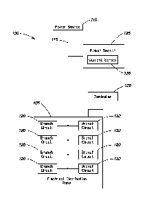
[0016] Figure 1 is a functional block diagram depicting a load estimation
system in accordance with an embodiment; and
[0017] Figure 2 is a flow chart depicting a method of estimating a load in
accordance with an embodiment.
Detailed Description
[0018] The systems and methods described herein are not limited in their
application to the details of construction and the arrangement of components
set forth
in the description or illustrated in the drawings. The invention is capable of
other
embodiments and of being practiced or of being carried out in various ways.
Also,
the phraseology and terminology used herein is for the purpose of description
and
should not be regarded as limiting. The use of "including" "comprising"
"having"
"containing" "involving" and variations thereof herein, is meant to encompass
the
items listed thereafter and equivalents thereof as well as additional items.
[0019] Figure 1 is a functional block diagram depicting an embodiment of a
load estimation system 100 that includes an electrical distribution panel 105,
a power
source 110, a main line 115, branch circuits 120, a power sensor 125, a
controller 130,
and a current sensor 135. The main line 115 couples the electrical
distribution panel
105 with the power source 110 and branches within the electrical distribution
panel
105 into a plurality of power lines for each of the plurality of branch
circuits 120 that
are included in the electrical distribution panel 105.
[0020] The electrical distribution panel 105 may include any distribution
6
CA 027821412012-05-28
WO 2011/079190
PCT/US2010/061772
board, panel board, or circuit breaker panel that divides an electrical power
feed into
the plurality of branch circuits 120. The electrical distribution panel 105
may also
include one or more circuit breakers or fuses, and in one embodiment is
enclosed in a
protective casing having a removable panel or door that grants access to the
branch
circuits 120 and/or their associated circuit breakers. In one embodiment, the
circuit
breakers are remotely operated circuit breakers that provide overcurrent
protection
and have an integral operator that selectively and reversibly turns the
circuit breakers
on and off. For example, circuit breakers described herein include the
Powerlink
series of remotely operated circuit breakers provided by the Schneider
Electric USA
Inc.
[0021] During operation, the electrical distribution panel 105 cycles
through a
plurality of different states. For example, in one state each branch circuit
120 is
coupled with the main line 115. In another state one branch circuit is
decoupled with
the main line 115 with every other branch circuit coupled. In one embodiment,
these
iterations continue until the cycle is complete. In another state a first
plurality of
branch circuits are coupled and a second plurality of branch circuits are
decoupled. It
is appreciated that any combination of zero or more branch circuits 120 may be
coupled or decoupled from the main line 115 during a time period based on the
state
of the corresponding circuit breaker and its associated controller. The
controller 130
controls switching operations to reversibly couple branch circuits 120 with
the main
line 115, or determines that a switching operation has occurred without having
controlled or instructed that switching operation.
[0022] The branch circuits 120 supply power to any type of load, such as
lighting loads that are constant or variable, known or unknown. For example,
when
branch circuit loads are substantially constant but unknown, the current
sensor 135
determines the total current of the electrical distribution panel 105 based on
measurements at the main line 115. This total current is proportioned to each
branch
circuit 120 load based, for example, on the change in total electrical
distribution panel
7
CA 027821412012-05-28
WO 2011/079190
PCT/US2010/061772
105 load resulting from the coupling and decoupling of branch circuits 120
with the
main line 115.
[0023] The power sensor 125, which may be referred to as a meter, measures
the overall power draw of the electrical distribution panel 105 at the main
line 115
without requiring individual branch circuit 120 power measurements, and
determines
this power draw when the electrical distribution panel 105 is in various
states, i.e.,
when some branch circuits 120 are active and others are inactive. In one
embodiment,
total power usage of the main line 115 at a period of time is the sum of the
power
usage of each branch circuit 120 coupled to the main line 115 at that period
of time.
The controller 130 evaluates this power draw information to estimate branch
circuit
loads of the branch circuits 120.
[0024] In one embodiment, power sensor 125 includes a current sensor 135.
The current sensor 135 meters current of main line 115 when any number of
branch
circuits 120 are coupled or decoupled with the main line 115. In one
embodiment
where power source 110 includes a three phase power source, current sensor 135
includes a current transformer for each phase to measure current before and/or
after
the branch circuits 120 switch states. The controller 130 and the current
sensor 135
determine changes in current that result from this load switching. The
controller 130
or the power sensor 125 calculates power usage of the electrical distribution
panel 105
at a particular switching state based on the metered current and a
corresponding
voltage.
[0025] The controller 130 determines the time period that one of the branch
circuits 120 is coupled to the main line 115. The controller 130 also tracks
the status
of the branch circuits 120 to determine if they are coupled (e.g., active or
drawing
power) with the main line 115 or decoupled (e.g., inactive or not drawing
power)
from the main line 115 during any time period. This information is combined
with
information from the power sensor 125 to determine total power usage of the
electrical distribution panel 105 and to estimate the energy usage of the
branch circuit
8
CA 027821412012-05-28
WO 2011/079190
PCT/US2010/061772
120. In an illustrative embodiment, the power sensor 125 determines the total
power
drawn by the electrical distribution panel 105 during a time period when at
least two
of the branch circuits 120 are coupled to the main line 115. Subsequent to the
decoupling of one of the two branch circuits 120, the power sensor 125
determines
power drawn by the electrical distribution panel 105 with one of the two
branch
circuits 120 decoupled and the other of the two branch circuits 120 coupled to
the
main line 115. In this example, this difference in electrical distribution
panel 105
power is attributed to the power draw of the decoupled branch circuit 120.
[0026] In some embodiments, the controller 130 includes a processor, logic
circuit, application specific integrated circuit, any associated software,
memory,
firmware, hardware, and combinations thereof. The controller 130 can also
include
different logic devices located in different areas, such as a processor or
other logic
device located within electrical distribution panel 105 in combination with
one or
more other logic devices remote to electrical distribution panel 105.
Controller 130
can include control devices provided in the Powerlink series of circuit
breakers
provided by the Schneider Electric USA Inc. In one embodiment, power sensor
125
and controller 130 are part of the same device.
[0027] In operation of the system 100, based at least in part on
information
from the power sensor 125, the controller 130 estimates power for individual
branch
circuits 120. For example, the controller 130 tracks the accumulated ON time
for
individual branch circuits 120. The number of hours (H) accumulated for each
branch
circuit 120 in a time period, e.g., month, is multiplied by the power (KW) of
each load
to estimate the kilowatt-hours (KWH) of a branch circuit 120 load. The branch
circuit
120 switching between coupled and decoupled states affects overall electrical
distribution panel 105 energy usage because decoupled branch circuits 120 draw
little
or no power. By coordinating overall electrical distribution panel 105 power
with
load switching as the branch circuits 120 couple and decouple with electrical
distribution panel 105, the controller 130 estimates power consumption of an
9
CA 027821412012-05-28
WO 2011/079190
PCT/US2010/061772
individual branch circuit 120.
[0028] In one embodiment, power sensor 125 determines main line 115 power
as loads of electrical distribution panel sequence from ON to OFF, e.g., when
a
branch circuit 120 changes from a coupled state to a decoupled state, or is
disconnected from the main line 115. The change, e.g., drop, in power or
current is in
this example attributable to the branch circuit 120 that has sequenced off.
Continuing
with this illustrative embodiment, to estimate power of individual branch
circuits 120,
i.e., power representing the load demand of branch circuit 120, the power
sensor 125
determines electrical distribution panel 105 power usage before and after one
branch
circuit 120 changes state, as represented by equation (1) below, where KWT is
the
total power demand of electrical distribution panel 105, KWx is the power
demand of
one branch circuit 120, and C, is the state of each branch circuit 120, e.g.,
open/closed
or decoupled/coupled with C, having a value of 1 for the closed or coupled
state and 0
for the open or decoupled state.
(1) KWT = KWI(Ci) + KW2(C2) + KW3(C3) + === = KWN(CN)
[0029] Equations (2) ¨ (5) below illustrate branch circuit 120 power
estimation when the branch circuit 120 couples or decouples from the main line
115,
where the total power demand is the sum of individual power demands of branch
circuits 120. Equation (2) illustrates an example at a first sample time where
all
branch circuits 120 are coupled (i.e., ON or in state = 1 at time C=1) with
the main
line 115.
(2) KWTTI = KW1(1) + KW2(1) + KW3(1) + = KWN(1)
[0030] In equation (3) below, at a second sample time all branch circuits
120
are coupled (i.e., ON with state = 1) except branch circuit #1, which is
decoupled (i.e.,
OFF with state = 0) at time 2 (i.e., C=2).
(3) KWTT2 = KW1(0) + KW2(1) + KW3(1) + = KWN(1)
[0031] Continuing with this example, the controller 130 determines the
power
CA 027821412012-05-28
WO 2011/079190
PCT/US2010/061772
demand of branch circuit #1, which switches between a coupled state (equation
2) and
a decoupled state (equation 3) as the difference between equations (2) and
(3), in
accordance with equations (4) and (5) below:
(4) KWTri - KWTT2 = [KW1(1) + KW2(1) + KW3(1) + KWN(1)] ¨ [KW1(0) +
KW2(1) + KW3(1) + KWN(1)]
(5) KWTri - KWTT2 = KW1 = kilowatt demand of the first branch circuit 120.
[0032] This power demand of a branch circuit may be influenced by voltage
variations of the main line 115. In this example, power demand of the branch
circuits
120 is estimated as a ratio of the branch circuit 120 power demand to the
total
electrical distribution panel 105 power demand during a time period.
Continuing with
this example, total demand at the second sample time illustrated in equation 3
is
divided by the total demand at the first sample time of equation 2 to
determine a ratio
of the effect that the power demand branch circuit #1 had on the total power
of the
electrical distribution panel 105. This ratio is used to estimate the branch
circuit #1
power demand at any time based on the instantaneous total demand, as
illustrated in
equation (6) below, where X1 represents a ratio of the branch circuit #1 power
demand to total electrical distribution panel 105 power demand.
(6) X1 = KWi/KWri
[0033] The operations in equations (1) to (6) can be performed for any
branch
circuit 120 of the electrical distribution panel 105 and in one embodiment,
the
operations are performed for each branch circuit 120 to create a set of power
demand
estimates for each branch circuit 120, as well as ratios of individual branch
circuit 120
power demand to total electrical distribution panel 105 power demand, as
illustrated
in equations (7) and (8).
(7) KWT = KW1 + KW? + KW3 + KWN
(8) 100% = Xi + X2 + X3 + XN
[0034] It is appreciated that equations (7) and (8) illustrate an
embodiment
11
CA 027821412012-05-28
WO 2011/079190
PCT/US2010/061772
where the branch circuits 120 can be switched off, e.g. decoupled to obtain
individual
ratios. if, for example, some branch circuits 120 are not switched off, then
the sum of
the estimated branch circuit 120 power demands may not equal the total
electrical
distribution panel 105 power demand, and the sum of the individual branch
circuit
120 ratios may not equal 100%, as illustrated in equations (9) to (13), where
KWu
represents an unswitched power demand, Xs is the sum of the switched ratios,
and Xu
is the unswitched ratio, where the unswitched power demand may be recorded for
use
in calculations performed by the controller 130.
(9) KWT = KW1 + KW) + KW3 + KWN + KWu
(10) KWu = KWT ¨ (KW] + KW2 + KW 1+ KWN)
(11) 100% = Xs + Xu
(12) 100% = (Xi + + X3 -F... XN) Xu
(13) Xu = 100% ¨ (Xi + X2 X3 XN)
[0035] Although the branch circuit 120 power demand of equations (1) to
(13)
represents branch circuit load, the ratio XN is used to estimate the branch
circuit 120
power demand of a branch circuit N at any time based at least in part on the
total
electrical distribution panel 105 power demand, e.g., the instantaneous
electrical
distribution panel 105 power demand. For example, to estimate demand for
branch
circuit #1 where the instantaneous electrical distribution panel 105 power
demand is
KWT, the ratio of individual branch circuit #1 demand to total electrical
distribution
panel 105 power demand is Xi = KWi/KWT, the estimated demand for the first
branch circuit 120 (KWEi) is represented by equation (14).
(14) KWEI = KWT * Xi
[0036] The estimated power demand of equation 14 does not require a
manually initiated learning sequence, so that the power sensor 125 uses a
single
sampled main line 115 power usage value as a beginning seed value to determine
the
energy usage of the branch circuit 120. Consider that a single change in
12
CA 027821412012-05-28
WO 2011/079190
PCT/US2010/061772
current/power can be manually initiated and a corresponding sample can be
captured
to -learn" the circuit's demand. This sample can be used as a representative
value
from that time forward. But calculations based on a single sample can be
problematic, especially when accumulated over time. Thus, in the most basic
method
described there may be some inaccuracy that can be reduced by averaging
multiple
samples. While obtaining multiple samples can be tedious if the trigger and
capture
process is manually initiated, if the method to control a branch circuit ON
and OFF is
automatic, such as with PowerLink breaker system, then the means exists to
automate the capture of multiple samples. Thus one may use the very first
sample as
a seed value for what will become a "smoothed" or "moving" average by using
subsequent samples to be combined with the first sample for improving accuracy
as
time goes on. This technique also has an advantage in that it would account
for
changing load characteristics.
[0037] In one embodiment, varying branch circuit loads skew estimated
demand for a branch circuit 120 (e.g., KWEi) because the variances affect the
total
electrical distribution panel 105 power demand. For example, the power sensor
125
samples the main line 115 power (e.g., total electrical distribution panel 105
input
power) each time the branch circuit 120 changes state to couple or decouple
with the
main line 115, and load variances that occur over time become averaged into a
power
demand estimate or ratio of branch circuit 120 power demand to total
electrical
distribution panel 105 power demand.
[0038] In one embodiment, energy of the branch circuit 120 is estimated for
a
first time period where energy includes estimated branch circuit 120 power
demand
multiplied by the time in which that branch circuit 120 is ON, as illustrated
in
equation (15) where H111 is the accumulated ON time of a first branch circuit
120 at a
first point in time.
(15) KWHT1 = KWI * H1T1
[0039] Energy of the same or a different branch circuit 120 is also
estimated
13
CA 027821412012-05-28
WO 2011/079190
PCT/US2010/061772
for a second time period with respect to the first time period of equation
(15). For
example, accumulated branch circuit 120 energy is illustrated in equation (16)
where
H1T2 is the accumulated ON time of the first branch circuit 120 at a second
point in
time.
(16) KWHT-) = KW' * H1T2
[0040] In this example, first branch circuit 120 energy for the time period
between the first and second points in time, KWHi is the difference between
equations (16) and (15), as illustrated in equation (17).
(17) KWHI = KWHT7 ¨ KWHT1 = (KW1* H112) ¨ ( KW * HiTO or KW1(HiT2
[0041] In one embodiment, the power sensor 125 determines power of
electrical distribution panel 105 responsive to detection by the controller
130 of the
branch circuit 120 state change from OFF to ON, (e.g., open circuit to closed
circuit;
or decoupled to coupled) or from ON to OFF. In both configurations the
controller
130 uses the resulting estimated branch circuit 120 power demand to estimate
the
energy use of the branch circuit 120, as illustrated in equations (15) to
(17). It is
appreciated that this estimate, as well as other controller 130, power sensor
125, and
current sensor 135 information are stored as needed in one or more associated
electronic memory units.
[0042] In one embodiment, the controller 130 estimates power factor for the
branch circuit 120. As discussed above, the current sensor 135 meters current,
and
the power usage is determined based on the corresponding voltage. In this
illustrative
embodiment, power factor is estimated using equations (18) to (23), where
equation
(18) determines a change in real power allocated to a first branch circuit
120, equation
(19) determines a change in current allocated to the first branch circuit 120,
and
equation (20) determines voltage identified before the first branch circuit
120 opens.
(18) KW' = KWT2 ¨ KWT1
14
CA 2782141 2017-04-10
(19) Ii = IT2¨ITi
(20) Vi = VU
Power factor (PF) of the first branch circuit PF1 is determined using
equations
(21) to (23).
(21) PF = P (Real Power) / S (Apparent Power)
(22) Ph= (KWT2 ¨ KW-0 / ((IT2 ¨ IT1)(VTI))
(23) Pr) = KW1 / (Ii * VU)
100431 In one embodiment, the controller 130 estimates energy usage of
branch circuits 120 by periodically capturing data sets containing total power
usage of
electrical distribution panel 105 for a plurality of states, where identified
branch
circuits 120 are closed (e.g., coupled) in each state. In this embodiment
matrix
algebra operations determine individual branch circuit 120 energy usage.
[0044] In one embodiment, branch circuit load estimation includes systems
and methods for virtual branch load management as described in U.S. Patent
7,526,393, entitled Virtual Branch Load Management, filed on September 25,
2007,
which is assigned to the assignee of the present invention.
[0045] Figure 2 is a flow chart depicting a method 200 of estimating power
draw of a load in accordance with an embodiment. In one embodiment, method 200
includes acts of determining total power usage of an electrical distribution
panel
having a plurality of branch circuits (ACT 205), determining a first power
usage of
the electrical distribution panel with a first branch circuit decoupled from
the main
line (ACT 210), identifying a time period that the first branch circuit is
coupled to the
main line (ACT 215), and estimating energy usage of the first branch circuit
(ACT
220).
[0046] ACT 205 determines total power usage of the electrical distribution
CA 027821412012-05-28
WO 2011/079190
PCT/US2010/061772
panel based on characteristics of the main line that provides power to the
branch
circuits, with one of the branch circuits coupled to the main line. For
example, a
power or current sensor meters the main line to determine the total power
usage (ACT
205). By determining total power usage (ACT 205) at the main line, it is not
necessary to determine power usage at the branch circuit level. In one
embodiment,
determining total power usage (ACT 205) includes a current sensor to identify
main
line current and calculating the total power usage based on the main line
current and a
corresponding voltage. In one embodiment, total power usage is determined (ACT
205) with a plurality of branch circuits simultaneously coupled to the main
line. Total
electrical distribution panel power usage is determined (ACT 205) during any
state of
the electrical distribution panel, e.g., with any combination of branch
circuits being
coupled and decoupled to the main line of the electrical distribution panel.
In one
embodiment, the electrical distribution panel cycles through a plurality of
different
states with the total power usage of the electrical distribution panel
determined (ACT
205) for a state of the cycle based at least in part on main line current or
power
characteristics.
[0047] A first power usage value is determined (ACT 210) based on main line
characteristics with one of the plurality of branch circuits decoupled from
the main
line. For example, a power sensor senses main line power when all but one of
the
branch circuits are coupled with the main line, with one branch circuit
decoupled, or a
current sensor meters the main line current and determines this power usage
value
(ACT 210) based on the metered current and a corresponding voltage.
[0048] In one embodiment, the first power usage value is determined (ACT
210) subsequent to a detected decoupling of a branch circuit that occurs when,
for
example, the controller detects a state change of the branch circuit from an
ON state
to an OFF state. The controller may, but need not directly control this state
change.
For example, a remotely operated circuit breaker with a dedicated integral
controller
can be controlled to turn the circuit breaker on or off to change the state of
the branch
16
CA 027821412012-05-28
WO 2011/079190
PCT/US2010/061772
circuit. The determined first power usage (ACT 210) is less than the
determined total
power usage (ACT 205) due to power attributable to the decoupled branch
circuit,
where the decoupling is detected when a circuit breaker or other type of
switch
interrupts the electrical connection between the branch circuit and the
electrical
distribution panel. In one embodiment, the detected decoupling marks the end
of the
time period that an identified branch circuit is coupled with the main line,
identified in
ACT 215.
[0049] Method 200 also estimates branch circuit energy usage (ACT 220) for
any branch circuit of the electrical distribution panel for any time period,
as indicated
in equations (1 ¨ 23) above. In one embodiment, branch circuit energy is
estimated
(ACT 220) for a time period based on the identified first time period that a
branch
circuit is decoupled from the main line (ACT 215), and the differential
between the
determined total power usage (ACT 205) and the determined first power usage
(ACT
210). For example, total power usage is determined (ACT 205). Subsequently,
one
of the branch circuits is decoupled from the main line, and a first power
usage that is
less than the total power usage is determined (ACT 210). Energy usage of the
first
branch circuit is estimated (ACT 220) based on the time the branch circuit is
coupled
with the main line and the determined power usage attributable to that branch
circuit.
[0050] In one embodiment, estimated branch circuit energy (ACT 220) values
are averaged with other estimated energy values determined for the same branch
circuit at a different time period. For example, the estimated branch circuit
energy
usage (ACT 220) for one day is averaged with estimated energy usage values of
the
same branch circuit for previous days to estimate energy usage of that branch
circuit
for any time period, such as a week or month. In one embodiment, these
averages are
weighted to account, for example, for differences between the lengths of the
time
periods.
[0051] Note that in Figures 1 and 2, the enumerated items are shown as
individual elements. In actual implementations of the systems and methods
described
17
CA 027821412012-05-28
WO 2011/079190
PCT/US2010/061772
herein, however, at least some of these items may be inseparable components of
other
electronic devices such as a digital computer. Thus, actions described above
may be
implemented at least in part in software that may be embodied in an article of
manufacture that includes a program storage medium. The program storage medium
includes data signals embodied in one or more of a carrier wave, a computer
disk
(magnetic, or optical (e.g., CD or DVD, or both)), non-volatile memory, tape,
a
system memory, and a computer hard drive.
[0052] From the foregoing, it will be appreciated that the systems and
methods described herein afford a simple and effective way to estimate branch
circuit
energy usage based on main line or power source power determinations, where
the
main line provides power from the power source to a plurality of branch
circuits. The
systems and methods according to various embodiments are able to estimate
branch
circuit energy usage without direct branch circuit level power readings. This
increases efficiency and compatibility, and lowers cost by, for example,
eliminating
individual branch circuit power sensors.
[0053] Any references to front and back, left and right, top and bottom, or
upper and lower and the like are intended for convenience of description, not
to limit
the present systems and methods or their components to any one positional or
spatial
orientation.
[0054] Any references to embodiments or elements or acts of the systems and
methods herein referred to in the singular may also embrace embodiments
including a
plurality of these elements, and any references in plural to any embodiment or
element or act herein may also embrace embodiments including only a single
element.
References in the singular or plural form are not intended to limit the
presently
disclosed systems or methods, their components, acts, or elements to single or
plural
configurations. For example, references to "one" element or act includes at
least one
element or instance of the act unless explicitly indicated to the contrary by
referring to
"only one" or "exactly one" element or act.
18
CA 027821412012-05-28
WO 2011/079190
PCT/US2010/061772
[0055] Any embodiment disclosed herein may be combined with any other
embodiment, and references to "an embodiment," "some embodiments," -an
alternate
embodiment," "various embodiments," "one embodiment" or the like are not
necessarily mutually exclusive and are intended to indicate that a particular
feature,
structure, or characteristic described in connection with the embodiment may
be
included in at least one embodiment. Such terms as used herein are not
necessarily all
referring to the same embodiment. Any embodiment may be combined with any
other embodiment in any manner consistent with the aspects and embodiments
disclosed herein.
[0056] References to "or" may be construed as inclusive so that any terms
described using "or" may indicate any of a single, more than one, and all of
the
described terms.
[0057] Where technical features in the drawings, detailed description or
any
claim are followed by references signs, the reference signs have been included
for the
sole purpose of increasing the intelligibility of the drawings, detailed
description, and
claims. Accordingly, neither the reference signs nor their absence have any
limiting
effect on the scope of any claim elements.
[0058] One skilled in the art will realize the systems and methods
described
herein may be embodied in other specific forms without departing from the
spirit or
essential characteristics thereof. For example, a main line can provide power
to more
than one electrical distribution panel, where each panel includes a plurality
of branch
circuits. Further, individual circuit characteristics can be estimated without
direct
measurement of individual circuit current and different branch circuits can
have
different characteristics. The foregoing embodiments are therefore to be
considered
in all respects illustrative rather than limiting of the described systems and
methods.
Scope of the systems and methods described herein is thus indicated by the
appended
claims, rather than the foregoing description, and all changes that come
within the
meaning and range of equivalency of the claims are therefore intended to be
embraced
19
CA 02782141 2012 05 28
WO 2011/079190
PCT/US2010/061772
therein.