Note : Les descriptions sont présentées dans la langue officielle dans laquelle elles ont été soumises.
1
A BALE CUTTING APPARATUS AND METHOD
The present invention relates to a bale cutting apparatus and method. Fodder
is
wrapped in large bales which are covered in layers of wrapping materials to
hold the
bale together and/or to protect the contents from contact with air. Various
types of
apparatus are used for handling these bales including bale spikes, bale grabs
and
other handling apparatus.
A major problem with the handling of bales is that the outer bale covering
materials,
which are typically plastics coverings, and any inner covering, such as
plastic meshing,
net wrap, string or twine, must all be removed before the fodder is fed to
animals either
directly along a feeding passageway in a slatted shed or if fed using a
feeding wagon.
This is a particular problem because if the plastics material goes into the
feeding
wagon it may become entangled into the mixing apparatus or get chopped into
small
pieces and distributed with the animal feed which could lead to catastrophic
consequences.
In practice, a tractor operator will typically be required to leave the cab of
the tractor in
order to cut and remove the wrappings from around a bale, and this is not only
time
consuming but also dangerous since the operator is entering an extremely
hazardous
environment in which engagement with heavy machinery is required. Moreover,
the resulting smell and odour of the silage on an operator's shoes and
clothing
after completing such a task is extremely unpleasant.
An object of an aspect of the invention is to provide a wrapped bale handling
apparatus which alleviates the above disadvantages.
Accordingly, in one aspect there is provided a bale cutting apparatus of the
type
comprising attachment means for coupling the apparatus to a prime mover, and a
cutting means to cut through a bale containing fodder, the cutting means being
operable to retain the bale against a stop member and to prevent the bale from
moving
under force of gravity away from the stop member, wherein the cutting means is
further operable to commence the cutting operation at the base of the bale and
to
move upwardly through the bale to cut through the bale such that at the
conclusion of
the cutting operation, the cutting means is at the uppermost point of its
travel and
cooperates with the stop member in retaining bale covering materials so that
the
CA 2783141 2018-05-18
2
fodder is discharged from the bale without the bale covering materials being
dispensed
with the fodder.
The present invention eliminates the need to separately remove the wrapping
materials and then split the bale, which alleviates the aforementioned
problems.
In another embodiment, the bale may be supported substantially by the cutting
means
during cutting.
In another embodiment, the cutting means may be operable to move toward the
stop
member as the bale is cut and to stop at a point adjacent the stop member.
In another embodiment, the movement of the cutting means may stop after a
leading
portion of the cutting means penetrates a receiver of the stop member.
In another embodiment, the receiver may be a channel in the stop member.
In another embodiment, the cutting means may comprise a hydraulically operable
cutter pivotally mounted on and movable on the apparatus.
In another embodiment, the hydraulically operable cutter may comprise a pair
of
pivotally mounted arms and a transversely disposed knife member.
In another embodiment, the knife member may include a plurality of blades for
cutting
the covering materials and the fodder.
In another embodiment, the cutting means may be movable arcuately through the
bale
to cut the fodder and the covering materials.
In another embodiment, the apparatus may further comprise gripping means
operable
to grab and hold the bale covering materials.
In another embodiment, the gripping means may be located at or adjacent the
stop
member of the apparatus so that when the bale is retained against the stop
member
the gripping means grabs the covering materials.
CA 2783141 2018-05-18
3
In another embodiment, the gripping means may comprise a pair of clamps which
are
hydraulically operable to engage with the covering materials together with
knife or
blade members of the cutting means.
In another embodiment, the cutting means may be movable towards and between
the
pair of clamps.
In another embodiment, the clamps may have a longitudinal length which is
substantially the same as the longitudinal length of the cutting means.
In another embodiment, the apparatus may further comprise a generally curved
frame
structure and in which the stop member and cutting means is provided on the
frame.
In another embodiment, the apparatus may further comprise a plurality of tines
which
project substantially orthogonally from the frame structure.
In another embodiment, the frame structure may be pivotally coupled to the
prime
mover.
In another embodiment, there is provided a prime mover coupled to such a bale
cutting
apparatus.
In another aspect, there is provided a method for cutting a bale containing
fodder in a
cutting apparatus comprising a cutting means and a stop member, the method
comprising operating the cutting means to retain the bale against the stop
member and
to prevent the bale from moving under force of gravity away from the stop
member
wherein the cutting means is then operated to commence the cutting operation
at the
base of the bale and to move upwardly through the bale to cut through the bale
such
that at the conclusion of the cutting operation, the cutting means is at the
uppermost
point of its travel and cooperates with the stop member in retaining bale
covering
materials so that the fodder is discharged from the bale without the bale
covering
materials being dispensed with the fodder.
In another embodiment, the method may comprise the further step of operating
the
cutting means so that the bale is substantially supported by the cutting means
during
cutting.
CA 2783141 2018-05-18
4
In another embodiment, the method may comprise the further step of operating
the
cutting means so that it moves toward the stop member as the bale is cut and
then
stops at a point adjacent the stop member.
In another embodiment, the method may comprise the further step of moving the
bale
cutting means arcuately through the bale to cut the fodder and the covering
materials.
In another embodiment, the method may comprise the further step of operating
gripping means to grab and hold the bale covering materials during cutting by
the
to cutting means.
In another embodiment, the method may comprise the further step of locating
the
gripping means at or adjacent the stop member so that when the bale is
retained
against the stop member the gripping means grabs the covering materials.
In another embodiment, the method may comprise the further step of operating a
pair
of hydraulically operable clamps of the gripping means to engage with the
covering
materials together with knife or blade members of the cutting means.
In another embodiment, the method may comprise the further step of moving the
cutting means towards and between the pair of clamps.
In another embodiment, the method may comprise the further step of mounting
the
stop member and the cutting means to a generally curved frame structure.
In another embodiment, the method may comprise the further step of pivotally
coupling
the generally curved frame structure to a prime mover.
In another aspect, there is provided a bale cutting apparatus of the type
comprising
attachment means for coupling the apparatus to a prime mover and a cutting
means to
cut through a bale containing fodder, the cutting means having an upwardly
directing
cutting edge and being operable to move toward a stop member as the bale is
cut and
to stop at a point adjacent the stop member, and to retain the bale against
the stop
member and to cut through the bale such that the fodder is discharged from the
bale.
In another embodiment, the bale may be supported substantially by the cutting
means
CA 2733141 2017-07-28
5
during cutting.
In another embodiment, the movement of the cutting means may stop after a
leading
portion of the cutting means penetrates a receiver of the stop member.
In another embodiment, the receiver may be a channel in the stop member.
In another embodiment, the cutting means may comprise a hydraulically operable
cutter pivotally mounted on and movable on the apparatus.
In another embodiment, the hydraulically operable cutter may comprise a pair
of
pivotally mounted arms and a transversely disposed knife member.
In another embodiment, the knife member may include a plurality of blades for
cutting
the covering materials and the fodder.
In another embodiment, the cutting means may be operable to commence the
cutting
operation at the base of the bale and is movable upwardly through the bale, so
that at
the conclusion of the cutting operation, the cutting means is at the uppermost
point of
its travel and cooperates with the stop member in retaining bale covering
materials so
that the fodder in the bale is dispensed without the covering materials being
dispensed
with the fodder.
In another embodiment, the cutting means may be movable arcuately through the
bale
to cut the fodder and any covering materials.
In another embodiment, the apparatus may further comprise gripping means
operable
to grab and hold bale covering materials.
In another embodiment, the gripping means may be located at or adjacent the
stop
member of the apparatus so that when the bale is retained against the stop
member
the gripping means grabs the covering materials.
In another embodiment, the gripping means may comprise a pair of clamps which
are
hydraulically operable to engage with the covering materials together with
knife or
blade members of the cutting means.
CA 2733141 2017-07-28
6
In another embodiment, the cutting means may be movable towards and between
the
pair of clamps.
In another embodiment, the clamps may have a longitudinal length which is
substantially the same as the longitudinal length of the cutting means.
In another embodiment, the apparatus may further comprise a generally curved
frame
structure and in which the stop member and cutting means is provided on the
frame.
In another embodiment, the apparatus may further comprise a plurality of tines
which
project substantially orthogonally from the frame structure.
In another embodiment, the frame structure may be pivotally coupled to the
prime
mover.
In another embodiment, there may be provided a prime mover coupled to such a
bale
cutting apparatus.
In such a further embodiment there may be also provided a method for cutting a
bale
containing fodder, the method comprising the steps of operating a cutting
means
having an upwardly directing cutting edge to retain the bale against a stop
member,
and to move towards the stop member to cut through the bale, and to stop at a
point
adjacent the stop member such that the fodder is discharged from the bale.
In another embodiment, the method may comprise the further step of operating
the
cutting means so that the bale is substantially supported by the cutting means
during
cutting.
In another embodiment, the method may comprise the further step of operating
the
cutting means to commence the cutting operation at the base of the bale so
that during
cutting it is movable upwardly through the bale, so that at the conclusion of
the cutting
operation, the cutting means is at the uppermost point of its travel and
cooperates with
the stop member in retaining bale covering materials so that the fodder is
dispensed
without the covering materials being dispensed with the fodder.
CA 2733141 2017-07-28
7
In another embodiment, the method may comprise the further step of moving the
bale
cutting means arcuately through the bale to cut the fodder and bale covering
materials.
In another embodiment, the method may comprise the further step of operating
gripping means to grab and hold bale covering materials during cutting by the
cutting
means.
In another embodiment, the method may comprise the further step of locating
the
gripping means at or adjacent the stop member so that when the bale is
retained
against the stop member the gripping means grabs the covering materials.
In another embodiment, the method may comprise the further step of operating a
pair
of hydraulically operable clamps of the gripping means to engage with the
covering
materials together with knife or blade members of the cutting means.
In another embodiment, the method may comprise the further step of moving the
cutting means towards and between the pair of clamps.
In another embodiment, the method may comprise the further step of mounting
the
stop member and the cutting means to a generally curved frame structure.
In another embodiment, the method may comprise the further step of pivotally
coupling
the generally curved frame structure to a prime mover.
In still another aspect, there is provided a bale cutting apparatus of the
type comprising
attachment means for coupling the apparatus to a prime mover and a cutting
means to
cut through a bale containing fodder, the cutting means being operable to
retain the
bale against a stop member so that the bale is prevented from moving under
force of
gravity away from the stop member by the cutting means, and the cutting means
is
further operable to cut through the bale and to stop after a leading portion
of the
cutting means penetrates a receiver of the stop member, such that the fodder
is
discharged from the bale and bale covering materials are retained
substantially at or
adjacent the stop member.
In another embodiment, the bale may be supported substantially by the cutting
means
during cutting.
CA 2783141 2018-05-18
8
In another embodiment, the receiver may be a channel in the stop member.
In another embodiment, the cutting means may comprise a hydraulically operable
cutter pivotally mounted on and movable on the apparatus.
In another embodiment, the hydraulically operable cutter may comprise a pair
of
pivotally mounted arms and a transversely disposed knife member.
In another embodiment, the knife member may include a plurality of blades for
cutting
the bale.
In another embodiment, the cutting means may be operable to commence the
cutting
operation at the base of the bale and is movable upwardly through the bale, so
that at
the conclusion of the cutting operation, the cutting means is at the uppermost
point of
its travel and cooperates with the stop member in retaining the bale covering
materials
so that the fodder is dispensed without the covering materials being dispensed
with the
fodder.
In another embodiment, the cutting means may be movable arcuately through the
bale
to cut the fodder and the bale covering materials.
In another embodiment, the apparatus may further comprise gripping means
operable
to grab and hold the bale covering materials.
In another embodiment, the gripping means may be located at or adjacent the
stop
member of the apparatus so that when the bale is retained between the cutting
means
and the stop member the gripping means grabs the covering materials.
In another embodiment, the gripping means may comprise a pair of clamps which
are
hydraulically operable to engage with the covering materials together with
knife or
blade members of the cutting means.
In another embodiment, the cutting means may be movable towards and between
the
pair of clamps.
CA 2733141 2017-07-28
9
In another embodiment, the clamps may have a longitudinal length which is
substantially the same as the longitudinal length of the cutting means.
In another embodiment, the apparatus may further comprise a generally curved
frame
structure and in which the stop member and cutting means is provided on the
frame.
In another embodiment, the apparatus may further comprise a plurality of tines
which
project substantially orthogonally from the frame structure.
In another embodiment, the frame structure may be pivotally coupled to the
prime
mover.
In another embodiment, there may be provided a prime mover coupled to such a
bale
cutting apparatus.
In still yet another aspect, there is provided a method for cutting a bale
containing
fodder, the method comprising the steps of operating a cutting means to retain
the
bale against a stop member so that the bale is prevented from moving under
force of
gravity away from the stop member by the cutting means, and then performing
the
further step of operating the cutting means to cut through the bale and to
stop after a
leading portion of the cutting means penetrates a receiver of the stop member,
so that
the fodder is discharged from the bale and bale covering materials are
retained
substantially at or adjacent the stop member.
In another embodiment, the method may comprise the further step of operating
the
cutting means so that the bale is substantially supported by the cutting means
during
cutting.
In another embodiment, the method may comprise the further step of operating
the cutting means to commence the cutting operation at the base of the bale so
that
during cutting it is movable upwardly through the bale, so that at the
conclusion of the
cutting operation, the cutting means is at the uppermost point of its travel
and
cooperates with the stop member in retaining the bale covering materials so
that the
fodder is dispensed without the covering materials being dispensed with the
fodder.
In another embodiment, the method may comprise the further step of moving the
bale
CA 2783141 2018-05-18
10
cutting means arcuately through the bale to cut the fodder and the bale
covering
materials.
In another embodiment, the method may comprise the further step of operating
gripping means to grab and hold bale covering materials during cutting by the
cutting
means.
In another embodiment, the method may comprise the further step of locating
the
gripping means at or adjacent the stop member so that when the bale is
retained
between the cutting means and the stop member the gripping means grabs the
bale
covering materials.
In another embodiment, the method may comprise the further step of operating a
pair
of hydraulically operable clamps of the gripping means to engage with the bale
covering materials together with knife or blade members of the cutting means.
In another embodiment, the method may comprise the further step of moving the
cutting means towards and between the pair of clamps.
In another embodiment, the method may comprise the further step of mounting
the
stop member and the cutting means to a generally curved frame structure.
CA 2733141 2017-07-28
CA 02783141 2012-06-05
WO 2011/070037 PCT/EP2010/069109
11
In another embodiment of the invention, the method comprises the further step
of pivotally
coupling the generally curved frame structure to a prime mover.
The invention will hereinafter be more particularly described with reference
to the
accompanying drawings, which show by way of example only, one embodiment of a
bale
cutting apparatus according to the invention. In the drawings:
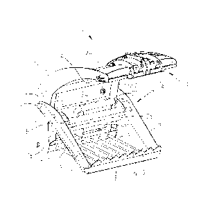
Fig. 1 is a perspective view of a bale cutting apparatus shown in an open
position
according to the present invention;
Fig. 2 is a side diagrammatic of the bale cutting apparatus of Fig. 1 shown in
an open
position about to engage a wrapped bale of fodder;
Fig. 3 is a side diagrammatic of the bale cutting apparatus of Fig. 1 engaging
with the
wrapped bale of fodder;
Fig. 4 is a perspective view of the bale cutting apparatus shown in Fig. 1
coupled to the
arms of a prime mover and about to begin a cutting operation;
Fig. 5 is a side diagrammatic of the bale cutting apparatus in which a lower
part of the
bale is being penetrated;
Fig. 6 is a perspective view showing the bale cutting apparatus coupled to a
prime mover
and penetrating through a bale of fodder;
Fig. 7 is a side diagrammatic showing the bale cutting apparatus penetrating
further into
the bale and fodder being discharged from the bale;
Fig. 8 is a perspective view showing the bale cutting apparatus completely
penetrated
through the bale with all fodder discharged with the covering materials
retained by the
gripping means;
Fig. 9 is a side diagrammatic view showing the bale cutting apparatus holding
covering
materials separated from the discharged fodder;
Fig. 10 is a side diagrammatic view showing the bale cutting apparatus
releasing covering
materials separated from the discharged fodder;
CA 02783141 2012-06-05
WO 2011/070037 PCT/EP2010/069109
12
Figs. 11 a and lib are detailed side diagrammatic views of clamps of a
gripping means
grabbing covering materials in which the bale is wrapped;
Fig. 12 is a perspective view of the clamps shown in Figs. lla and 11b; and
Fig. 13 is a schematic representation of a hydraulic circuit used to power the
bale cutting
apparatus.
Referring to the drawings, and initially to Figs. 1 to 10, there is shown a
bale cutting
apparatus, generally indicated by the reference numeral 1 of the type
comprising
attachment means, indicated generally by the reference numeral 2, for coupling
the
apparatus 1 to a prime mover (no shown). In the instance shown the apparatus 1
is
coupled to two arms 3 of the prime mover, but this should not be seen as
limiting since it
would also be possible to adapt the attachment means 2 so that it will couple
with a three-
point linkage or any other suitable connection system as required or as
desired.
Also shown is a cutting means, indicated generally by the reference numeral 4,
being
operable to cut through a bale 5 containing fodder 11. In the following
description the bale
5 will be described as a bale of fodder 11 which is wrapped in covering
materials 10 (see
Figs. 9 and 10), such as plastics coverings, which serve to hold the bale
together and
preserve the fodder from the air therefore promoting anaerobic fermentation,
which allows
the fodder to be stored for winter feeding. However, it will be appreciated
that the present
invention may also be used to cut bales 5 which have no such covering
materials 10
around the fodder 11.
The cutting means 4 is hydraulically operable and pivotally mounted and
movable on the
apparatus 1. The cutting means 4 comprises of a cutter having a pair of arms 7
which are
pivotally mounted to the apparatus 1 and a transversely disposed knife member
8 which
includes a plurality of blades 9 for cutting the bale 5 including the covering
materials 10
and the fodder 11.
The apparatus 1 further comprises a stop member, indicated generally by the
reference
numeral 13, which is provided as a bottom facing surface 14 at the top end of
a generally
curved frame structure 12. The curved frame 12 has a pair of curved side
members 23
which are connected together by round cross members 24 and square shaped cross
members 24 which give rigidity to the entire structure of the frame 12. A
plurality of tines
CA 02783141 2012-06-05
WO 2011/070037 PCT/EP2010/069109
13
15 project substantially orthogonally from the bottom end 16 of the frame
structure 12.
The tines 15 have ends of which are bolted or welded in position to a box
section 21 at the
lower end of the frame 12. The tines 15 may be used for transporting bales 5,
such as by
piercing into them or being used to nudge the bales 5 into a desired
position.. The cutting
means 4 is also shown pivotally mounted to the frame 12 and so that the pair
of hydraulic
rams are used to move the cutting means 4 up and down about the pivot point 26
of the
frame 12. A fixed bar 27 and a back panel 29 are also provided to stop the
bale from
moving too far toward the rear of the apparatus 1. An angled box section 28 is
also
provided to apply a pressure to the covering materials 10 during cutting to
assist in
moving the materials 10 away from the bale 5.
Figs. 11 and 12 show the operation of gripping means 17 of the apparatus 1
which is
operable to grab and hold the bale covering materials 10 wrapping the fodder
11 during
cutting. In the instance shown, the gripping means 17 is located at or
adjacent the stop
member 13 of the apparatus so that when the bale 5 is retained against the
stop member
13 the gripping means 17 grabs or pinches the covering materials 10. The
gripping
means 17 comprises one or more pairs of clamps 18 which are hydraulically
operable to
engage with and grab the covering materials 10. The clamps 18 are movable
towards
and away from a clamp receiver 22 by a hydraulic ram 20. By this action, the
covering
material 10 of the bale 5 is held by the clamp receiver 22 in conjunction with
the clamps
18 leaning against the outside of the surface of the clamp receiver 22. The
clamps 18 may
have a length which is substantially the same as the length of the knife
member 8 of the
cutting means 4. Although the gripping means 17 is shown being positioned at
or
adjacent the stop member 13 it will be understood that it may be also be
placed to good
effect at or adjacent any position on the frame structure 12 so that it can
successfully grip
the covering materials 10 around the bale 4. For example, the gripping means
17 may be
located along the back of the frame structure 12, such as on one or other of
the section
members 24, 25. Accordingly, reference to the gripping means 17 being provided
at or
adjacent the stop member 13 should not be seen as limiting.
As shown in Figs. 3 to 9, in operation, the cutting means 4 is operable to
push against and
so retain the bale 5 against the stop member 13. Thus operating the cutting
means 4 will
push against the bale 5 and urge the bale into a secure engagement with the
stop
member 13 so that the bale 5 is able to be securely held between the two
contact points
of the stop member 13 and the cutting means 4. As shown in Fig. 7, the bale 5
may be
lifted off the ground by the cooperation of the stop member 13 and the cutting
means 4
CA 02783141 2012-06-05
WO 2011/070037 PCT/EP2010/069109
14
which form a mouth to grip the bale 5 sufficiently so that the bale may
optionally be lifted
of the ground and prevented from moving under force of gravity away from the
stop
member 13 by the cutting means 4.
The cutting means 4 is operable to cut through the bale 5 such that the fodder
11 is
discharged from the bale 5 and any bale covering materials 10 are separated
and retained
by the apparatus 1. Before or whilst cutting, the apparatus 1 may be pivoted
or oriented
relative to the ground such that the blades 9 of the cutting means 4 are
upwardly directed
and the bale 5 is thereby supported substantially by the cutting means 4
during cutting. In
such a configuration, the cutting means 4 is operable to commence the cutting
operation
at the base of the bale 5 and is movable upwardly through the bale 5, so that
at the
conclusion of the cutting operation, the cutting means 4 is at the uppermost
point of its
travel and cooperates with the stop member 13 in retaining the covering
materials 10 so
that the fodder 11 is dispensed without the covering materials 10 being
dispensed with the
fodder 11. As shown, the cutting means 4 is movable arcuately through the bale
5 to cut
the fodder 11 and the covering materials 10. When the cutting means 4 applied
pressure
to the bale 5 the force of the cutting action forces the bale 5 against the
stop member 13
and when this happens it causes the top of the bale 5 to change shape and
deform which
forces the bale coverings 10 into the gripping means 17. In particular, the
covering
materials 10 are urged into a channel between the clamps 18 and the clamp
receivers 22.
It will however be understood that the apparatus 1 may be oriented or
appropriately
pivoted relative to the prime mover to which it is attached such that a
cutting operation
may also be commenced with the cutting means 4 cutting through a side or top
region of
the bale 5. This would present the cutting means 4 as having a transversely or
downwardly directed cutting edge or blade 9. The cutting means 4 is operable
to move
toward the stop member 13 as the bale is cut and to stop at a point adjacent
the stop
member 13. The movement of the cutting means 4 effectively stopping after a
leading
portion of the cutting means 4 penetrates a stop receiver formed as a channel
19 of the
.. stop member 13.
After cutting the bale 5 such that the fodder 11 has been discharged the
cutting means 4
is then moved away from the stop member 13, as shown in Fig. 9. The clamps 18
of the
gripping means 17 may then, when required, be released by the hydraulic ram 20
so that
the covering materials 10, which are by now fully separated from the fodder
11, may be
released from the bale cutting apparatus 1. The bale covering materials 10 may
be
CA 02783141 2012-06-05
WO 2011/070037 PCT/EP2010/069109
retained in different ways by the apparatus 1. In most instances the coverings
10 may be
retained by appropriate activation of the clamps 18 of the gripping means 17.
However, in
an alternative embodiment, the covering materials 10 may instead be retained
on the
cutting blades 9 where a gripping means 17 has not been provided or is not
being used
5 with the apparatus 1. In such an arrangement the covering materials 10
would be seen
resting on the blades 9 as the cutting means 4 is pivoted away from the stop
member 13.
A level of co-ordination of the clamps 18 of the gripping means 17 with the
cutting means
4 may be achieved by using the hydraulic unit shown in Fig. 13. The hydraulic
rams 30
10 which actuate the arms 7 of the cutting means 4, and the hydraulic ram
20 which operates
the clamps 18 are supplied from a prime mover, such as a tractor or a digger.
The clamps
18 are operated when cam valve opens 32, and such operation may optionally be
determined by the blade 9 position of the cutting means 4 as it is moved
toward or through
the bale 5. For example, the clamps 18 of the gripping means may be actuated
when the
15 cutting means 4 is about half way through cutting a bale 5. The valve 32
opens causing
the clamps 18 to move against the clamp receiver 22 to thereby grip the
covering
materials 10 when the cutting means 4 is at some pre-determined point in
carrying out a
cutting operation. After the bale 5 is cut and fodder 11 discharged the valve
33 may be
closed causing the clamps 18 to open and the plastics covering material to be
released.
In a further embodiment of the invention, the tines 15 may be adapted so as to
be
movable so that they can be used to retain the bale 5 against a stop member
13. In such
an embodiment the tines 15 are operable with the stop member 13 to thereby
grip the
bale 5 before the cutting means 4 is used to cut the bale 5.
It is to be understood that the invention is not limited to the specific
details described
herein which are given by way of example only and that various modifications
and
alterations are possible without departing from the scope of the invention as
defined in the
appended claims.