Note : Les descriptions sont présentées dans la langue officielle dans laquelle elles ont été soumises.
CA 02785843 2012-08-09
BEVERAGE FILTER CARTRIDGE
CROSS REFERENCE TO RELATED APPLICATIONS
This application claims the benefit of U.S. Provisional Application SN
61/522,05 1, filed August 10, 2011.
BACKGROUND OF THE INVENTION
1. Field of the Invention
The present invention relates to a cartridge for coffee, tea, and other
beverages in
amounts suitable for preparing single servings thereof in beverage makers
designed to
accommodate them.
2. Background of the Invention
Beverage filter cartridges used in specially designed beverage makers are well
known
in the art. Essentially, beverage filter cartridges of this type have included
an impermeable,
yieldably pierceable base shaped like a cup. A self-supporting wettable filter
element is
disposed in the cup and may be permanently sealed to an interior surface
thereof. The filter
element subdivides the space within the cup into first and second chambers.
The first
chamber, the space within the filter element, is for the material from which a
beverage may
be made, such as ground coffee. The second chamber is for collecting the
beverage dripping
from the filter element after a liquid, such as hot water, has been introduced
into the first
chamber. An impermeable, yieldably pierceable, imperforate cover is sealingly
engaged
with the top of the cup to form an impermeable cartridge.
In use in the machines designed to accommodate the beverage filter cartridges,
both
the cover and bottom of the beverage filter cartridge are pierced with sharp,
needle-like
(00400523. DOC. )
CA 02785843 2012-08-09
tubes. The piercing of the top cover admits hot water to the beverage filter
cartridge. The
brewed beverage flows out of the hole formed in the bottom of the cartridge by
the other
sharp, needle-like tube into a cup or mug for consumption by the user.
Machines and beverage filter cartridges of this general type have proven to he
immensely popular as they permit single servings of coffee, tea and other
beverages to be
prepared quickly and easily. However, as is well known to those who are in the
business of
producing and marketing coffee, the current single serving cartridges have
insufficient
volume of ground coffee to produce a hearty cup of brewed coffee with the
current
configuration. In addition to there being an inadequate quantity of ground
coffee, the flow of
hot water through the cartridge tends to back up as small particles clog the
bottom of the
filter during the brewing process. As the coffee brews there is a poor flow of
the brewed
liquid as the bottom of the filter, where the great bulk of the brewed liquid
exits the first
volume clogs. There is a need to provide an improved cartridge which allows
for a greater
volume of beverage forming material, like ground coffee, to be included within
the cartridge
and to provide alternate flow paths for the brewed beverage to exit the
cartridge as the
bottom of the filter becomes clogged. The present invention has been developed
to enable
the use of a greater volume of roasted coffee in a beverage filter cartridge
with a modified
shape and alternate channels for flow of brewed coffee in order to permit the
users to brew
an improved cup of coffee with a contemporary single-serving beverage brewing
apparatus.
SUMMARY OF THE INVENTION
Accordingly, it is an object of the present invention to permit an increased
volume of
roasted and ground coffee to be used in a single-serving beverage pod.
00400523. DOC. ; 2
CA 02785843 2012-08-09
It is another object of the present invention to permit an increased flow of
brewed
coffee or other beverage through alternate channels in the single-serving
beverage pod.
It is still another object of the present invention to provide a single-
serving beverage
pod with an extended tip region for the roasted and ground coffee, tea or
other beverage
forming materials which adjusts the brewing characteristics of the beverage
pod.
Still a further object of the present invention is a beverage pod with a
series of
radially oriented channels running downwardly around the perimeter of the
beverage pod
which enhance flow of the brewed beverage through the sides of the filter and
down through
the channels.
Yet another object of the invention is to form the outer side walls of the
single-serve
beverage pod with an oxygen blocking and scavenging additive which seals the
beverage
pod from the intrusion of oxygen, which causes the rapid reduction in quality
of the roasted
and ground coffee or tea or other beverage forming material.
It is a further object of the invention to improve the quality of beverages,
and in
particular, coffee, prepared with the use of single-serving technology.
Yet still a further objection of the invention is to provide a single-serving
beverage
pod which sits flat on a surface prior to use, with out gassing of carbon
dioxide from the
roasted coffee causing the upper cover to bow outwardly while the bottom cover
lays flat.
To these ends, a first embodiment of the present invention is a beverage pod
comprising a frustoconical sleeve, open at top and bottom, and having a larger
diameter at
the top than at the bottom. The sleeve terminates at the top at a flange. The
flange extends
outwardly around the top of the sleeve. A filter pouch for a beverage material
such as ground
coffee or tea leaves, is disposed within the sleeve. The top portion of the
filter pouch is
00400523. DOC. i 3
CA 02785843 2012-08-09
sealed to the inside surface of the sleeve proximate to the top thereof. Once
beverage
material has been placed in the filter pouch, a cover is sealed to the flange
extending about
the top of the sleeve to provide an oxygen barrier at the top of the sleeve. A
cover is also
sealed to the bottom of sleeve to form a sealed beverage pod. The top and
bottom covers are
pierced by a tubular needle which is a part of a beverage brewing machine.
The beverage pod may also include a plug, or stopper, which is inserted into
the
bottom edge of the sleeve to seal the bottom of the sleeve. The plug may be
held within the
bottom of the sleeve by an interference or screw fit, or be a part of the
bottom cover,
providing an oxygen barrier at the bottom of the sleeve. The plug may
incorporate a one-
way degassing valve of the types long-used in packages of coffee products, in
order to
permit gases escaping from the contents of the filter pouch to vent from the
sleeve, so that
pressure will not build up and cause any seal to rupture, all without
permitting any oxygen to
enter the sleeve. The plug is intended to be removed from the bottom edge of
the sleeve
immediately prior to use in a beverage brewing machine.
In a variation of this first embodiment, the beverage pod does not include a
plug or
stopper. Instead, the bottom of the frustoconical sleeve is open, so that the
beverage pod
may be used without first removing a plug. In this variation, a plurality of
beverage pods,
for example six or twelve of them, are provided in a resealable package of an
oxygen-barrier
material. The resealable package preferably includes a one-way degassing
valve.
A second embodiment of the present invention is a beverage filter cartridge
comprising a beverage filter pod and a reusable sleeve.
The beverage filter pod comprises a cap and a filter element for holding
materials
from which a beverage may be brewed. The cap is generally circular in shape
and is made
00400523. DOC.) 4
CA 02785843 2012-08-09
of a biodegradable material. The top of the cap has a central recessed portion
which is
thinner than other portions of the cap and designed to be pierceable by a
sharp, needle-like
tube in a single serving, beverage-making machine.
On the underside of the cap is a surface oriented at an oblique angle relative
to the
top of the cap, and extending circumferentially around the underside. The
filter element is
sealed to this surface once it has been filled with a brewable ingredient. The
cap finally also
has a flange extending about the perimeter of the cap above the oblique
surface. The flange
is used to stabilize the beverage filter pod on the sleeve.
The sleeve, perhaps made of plastic or some other durable material, is
designed to be
reused many times. In this regard, the use of the present beverage filter
system will
contribute less non-biodegradable waste than conventional beverage filter
cartridges.
The sleeve may be frustoconical in shape and have open ends. At the top end, a
shoulder extends around the inside surface of the rim. The shoulder has a
surface making an
oblique angle relative to the plane formed by the rim. The surface of the
shoulder cooperates
with the oblique surface on the underside of the cap to stabilize the cap when
the beverage
filter pod is disposed on the sleeve. The flange extending around the cap
enhances this
stability.
At the lower end of the sleeve is a flange oriented obliquely inward toward
the axis
of the sleeve both for stability of the sleeve as a whole and to prevent
liquid from getting
trapped within the sleeve. Within the sleeve proximate to but recessed from
the lower end
are cross beams which are provided to prevent a saturated filter element from
sagging low
enough to be punctured or torn by any element of the coffee maker. The upper
surfaces of
00400523. UOC. } 5
CA 02785843 2012-08-09
the cross beams are crowned or peaked to ensure that liquid on them will roll
off and
downward out of the sleeve.
In a fifth embodiment of the beverage filter cartridge, the outer cup has a
plurality of'
spaced vertical vents disposed circumferentially about the lower portion
thereof. The inner
surface of the outer cup has vertically oriented channels, each of which leads
to one of an
equal number of circumferentially disposed holes on the bottom. A central hole
is also
provided in the bottom. The holes and vents permit a brewed beverage to drain
from inside
the beverage filter cartridge.
Finally, in a sixth embodiment of the beverage filter cartridge, the outer cup
has a
recessed bottom with a plurality of circumferentially disposed holes. Within
the outer cup is
a plurality of vertically oriented channels, each leading to one of the holes
in the bottom.
The lower rim of the outer cup may be sealed with a bottom which is pierced by
the bottom
needle of the beverage making machine, or may have a plug, which may be
removed prior to
use on a coffee brewing machine. The plug may include a one-way degassing
valve.
In another preferred embodiment of the beverage filter cartridge, the body of
the
cartridge is formed as a frustoconical shell which is of greater diameter at
the top than at the
bottom, with a series of vertically oriented channels on the inside of the
shell arranged
radially around the body, each of the channels extending below the bottom of
the filter and
the bottom of the filter extending vertically below the plane that the bottom
needle reaches in
a central portion, the central portion being positioned inside the radius from
the center that
the bottom needle is positioned, so that the needle will not pierce the filter
in the central
portion or elsewhere and the beverage material in the central portion enhance
the fill
capacity of the beverage cartridge, enhances the quality of the flow rate
during the brew and
00400523. DOC. 6
CA 02785843 2012-08-09
creates a significant flow of brewed beverage out of the sides of the filter
into the channels
on the way out of the beverage cartridge.
The invention accordingly comprises the features of construction, combinations
of
elements and arrangements of part and processes which will be exemplified in
the
constructions and processes as hereinafter set forth, and the scope of the
invention will be
indicated in the claims.
BRIEF DESCRIPTION OF THE DRAWINGS
The present invention will now be described in more complete detail with
frequent
reference being made to the figures identified below.
Figure 1 is a front elevational view of a beverage cartridge constructed in
accordance
with a preferred embodiment of the invention;
Figure 2 is perspective view of a beverage cartridge constructed in accordance
with
the embodiment of Figure 1;
Figure 3 is a cross-sectional view of a beverage cartridge taken along line A-
A of
Figure 2;
Figure 4 is a perspective view of the beverage cartridge of the embodiment of
Figure
1;
Figure 5 is another perspective view of the beverage cartridge of the
embodiment of
Figure 1;
Figure 6 is a top plan view the beverage cartridge of the embodiment of Figure
1;
Figure 7 is a front elevational view of a filter utilized in the beverage
cartridge in the
embodiment of Figure 1;
00400523. DOC. } 7
CA 02785843 2012-08-09
Figure 8 is a cross sectional view of a beverage cartridge with a filter and
dry
beverage making material shown in accordance with the embodiment of Figure 1
Figure 9 is a perspective view of a filter bag used in the cartridge in
accordance with
the invention;
Figure 10 is a perspective view of a beverage cartridge in accordance with
another
embodiment of the invention;
Figure 11 is a perspective view of a beverage cartridge in accordance with
another
embodiment of the invention;
Figure 12 is a perspective view of a beverage cartridge in accordance with
another
embodiment of the invention;
Figure 13 is a perspective view of a beverage cartridge in accordance with
another
embodiment of the invention; and
Figure 14 is a perspective view of a beverage cartridge in accordance with
another
embodiment of the invention.
DETAILED DESCRIPTION OF THE PREFERRED EMBODIMENTS
Reference is made to Figures 1-7, wherein the single serving beverage
container,
generally indicated as 100, constructed in accordance with a preferred
embodiment of the
invention, is depicted. As seen in Figure 1, beverage cartridge 100 includes
central body
112, upper flange 114, top number 116 and bottom cover 118. In the current
preferred
embodiment the top cover 116 and the bottom cover 118 are oxygen impermeable
layers
which can be made either of foil or plastic layers which seal to the flange
114 at the top of
body 112 and to the bottom of body 112 as shown more particularly in other
views.
00400523.DOC.} 8
CA 02785843 2012-08-09
Reference is next made to Figure 2, which is a perspective view of beverage
cartridge
100 without top cover 116. As can be seen, body 112 has a series ofchannels
120 vertically
oriented running from proximate the top surface of body 112 to proximate the
bottom of
body 112. The channels are made in the sides of beverage cartridge 100 in a
fashion best
seen in Figures 3, 4 and 5.
With reference to Figure 4, the channels 120 are oriented radially around the
circumference of body 112 extending from near the upper flange 114 to the
bottom section
of body 112. As best seen in Figures 3, 4 and 5, the bottom surface of
beverage cartridge
body 112 includes a cage used to support the filter and beverage grinds placed
therein. The
cage is formed by ribs 132 extending to a central support platform 128 with an
inner dropped
cage volume 126 formed by vertical cage portions 122 and horizontal cage
portions 124.
The beverage machines (not shown), in accordance with the prior art, have an
upper
needle used for injecting hot water into the beverage cartridge 100 by
piercing upper cover
116 and a lower hollow needle (not shown), which is used to pierce a hole in
the bottom
cover 118 to allow the beverage to drain out of the cartridge 100. The lower
needle is
positioned off-center from the bottom center of the cartridge. Because the
cartridges are not
indexed into a particular orientation, the needle can, thus, pierce any
portion of the bottom
cover 118, which is the appropriate distance from the center where the needle
is located.
The traditional types of beverage cartridges, such as the Keurig brand K-Cup
beverage
cartridges, the filter with the ground coffee is maintained an adequate
distance from the base
of the cartridge so that when the bottom needle pierces the base of the Keurig
brand K-Cup
cartridge the needle does not also pierce the filter containing the coffee
grinds. However,
this approach limits the amount of coffee which can be utilized in the
beverage cartridge
{ 00400523. DOC. } 9
CA 02785843 2012-08-09
because the overall volume of the beverage cartridge is limited to the size
which fits within
the beverage machine. However, by utilizing the central cage, which extends
downwardly
below the level at which the lower needle pierces, but within the radius at
which it resides.
an additional volume is achieved for coffee or other dry material to brew a
beverage. In
addition to the benefit of additional volume of the dry particles, by adding a
deeper central
brewing area, the finer and/or slower dissolving particles within the filter
begin to clog the
bottom surfaces of the filter adding additional resistance. The increase in
resistance to the
flow of the brewed beverage redirects the water flow creating internal
turbulence, which
leads the liquid to be disbursed through the outer side vertical channels 120
of the cup. The
vertical channels provide a path for the brewed beverage to flow through all
of the filtered
surfaces simultaneously.
The bottom basket in the design formed by vertical members 122 and horizontal
members 124 produce several important benefits measured against designs that
do not have
this feature. This basket approach includes an increased internal fill volume
while
maintaining a needle barrier and support for the filter. It provides for an
increased open area
for brewed liquid to flow through with balanced resistance. The horizontal
portion 124 of
the basket provide a sealing area for the bottom, covered to maintain a flat
bottom surface
area so the cup sits level on a counter or other flat surface. The top cover
116 would flex
upward from the internal degassing pressure and not the bottom surface, which
is bound to
the rigid horizontal member 124. The sealing area on the bottom surface of the
cartridge 100
creates more precise tension.
With the cage system one can put in as much as 13.5 grams of coffee, 10 grams
of
tea or 20 grams of other soluble products for optimal flavor and intensity by
maximizing the
00400523. Doc. ) 10
CA 02785843 2012-08-09
internal volume. This allows the brew time to stay within the optimal 45 to 90
second range.
Testing the cage system in accordance with the invention has revealed high
levels of total
dissolved solids for all beverages.
Reference is next made to Figure 8, wherein a cross-sectional view of the
beverage
cartridge 100 in accordance with the invention is depicted in the beverage
making machine
with hollow needle 50 shown piercing the bottom cover 118 of cartridge 100.
The
remainder of the beverage making machine, constructed in accordance with the
prior art is
not depicted. A variety of machines operate in a similar fashion, one of which
is the Keurig
brand K-cup system brewing machines. Needle 50 is located a distance from the
center of
the base of cartridge 100 and the basket horizontal supports 124 and bulge
section 15 1 of
filter 150 are not pierced by needle 50 in use. In this way, the additional
volume created in
the bulge region allows additional coffee grounds or other beverage making dry
material to
fit within the cartridge 100 without affecting the overall volume of the
cartridge or creating a
situation where the needle 50 might inadvertently pierce the filter 150,
thereby allowing the
grinds to enter the brewed beverage. The beverage making machine is a
conventional
machine such as that sold by Keurig under the brand K-Cup brewing system. The
machines
are designed to receive a standard size beverage cartridge. They have the
needles at the top
to inject hot water or other heated liquid into the top of the cartridge (not
shown) and the
bottom needle 50 shown herein, which pierces the bottom of cartridge 100 to
allow the
brewed beverage to exit from the cartridge.
In the current preferred embodiment, the cartridge 100, including the side
wall 112,
flange 114 and cage members 122 and 124, are all formed from high density
polyethylene
(HDPE), which can be recycled under the number sign 2 symbol. In a preferred
00400523. DOC. 1 1
CA 02785843 2012-08-09
embodiment, the cup will be injection molded with the ability to add oxygen
scavenging
additives to the mix. When added, these additives will scavenge residual
oxygen in the cup
and act as an additional barrier, preventing oxygen from entering the cup and
extending its
shelf life.
The comparisons that were made between the existing, current market products,
such
as the Keurig brand K-Cup cartridges and the beverage cartridge in accordance
with the
invention were made using existing brewers, such as the Keurig brand K-Cup
machines.
Testing of various designs, including cups with varying channels mentioned and
hole
configurations yielded substantially different and unsatisfactory results.
Brew times
exceeding 90 seconds are not conducive to the convenience nature of the single
serving
market segment. In addition, they tend to produce a bitter-tasting, overly
extracted beverage.
Also, the flow characteristics of the cup designed with the cage produce a
good balance of
total dissolved solids and flavor within the optimum brew time for products of
this type.
The beverage container is suitable for use with coffee, tea or other soluble
products.
The additive which is utilized as the oxygen scavenging material has been used
primarily in PET applications for the beverage industry. However, using it
with the
monolithic HDPE material designed for use with the beverage cartridge 100 is
expected to
be able to maintain peak freshness for a minimum of 9 to 12 months. The brew
time was
measured using a stopwatch to determine the effects of different
configurations of the
beverage cartridge on brew time. Total dissolved solids was measured using a
total dissolve
solids measuring tool utilized in the industry and flavor was measured using a
specialty
coffee association cupping criteria.
00400523. Doc.) 12
CA 02785843 2012-08-09
The use of the channels 120 and cage 140 together were derived to address the
internal resistance during the brewing process of the traditional beverage
cartridge and the
desire to increase the volume of coffee and enhance the flavor of the brewed
coffee
beverage, without having the bottom needle puncture the filter. If the filter
is punctured,
then the grinds enter the brewed beverage, which is gritty and generally not
acceptable.
Because the beverage cartridge 100 constructed in accordance with the
invention is an
injection molded product with more wall stiffness than the conventional Keurig
brand K-
Cup design, the wall thickness can be made less creating an internal volume of
the cup can
be made slightly larger, with a slightly wider cup. Top and bottom dimensions
of the
beverage cartridge 100 have the same dimensions as the K-Cup so that it fits
smoothly into
the Keurig beverage machines, but has increased internal dimenion in the
middle section of
the cup.
As seen in Figure 4, the channels 120 are oriented radially about the
circumference of
the body 112 of cartridge 100. The channels run down to openings 130 proximate
the
support shelf 128 and horizontal ribs 132. In this way, with the filter in
place inside the
cartridge, the vertical side walls of the filter press up against the inside
surface of body 112
with the channels 120 creating a volume to allow the brewed beverage to exit
the filter and
freely run down the inside of cartridge 100 and out the bottom of openings 130
to the bottom
of the cartridge. The open channels running vertically along the inside of
body 112 create a
slight vacuum effect helping to draw the brewed beverage out of the sides of
the filter 150 so
that more of the heated water comes in contact with relatively fresh and dry
beverage
forming material while maintaining a good flow rate through the cartridge 100.
As the
bottom of the cartridge has been pierced in the beverage making process by the
lower needle
~ 00400523. DXC. } 13
CA 02785843 2012-08-09
50 of the beverage machine, the brewed beverage flows out of the bottom of the
cartridge.
The brewing process can be simplified to be the introduction of hot water into
contact with
the beverage forming material which causes the beverage to be brewed as the
solids and oils
in the beverage forming material join with the water and exit the beverage
cartridge as the
brewed beverage.
As seen in Figure 5, the horizontal section 124 formed in a crossing pattern
at the
base of the basket or cage 140, is generally coplanar with the base of body
112 so that the
bottom cover 118 can be secured both to the bottom perimeter of body 112 and
the flat
bottom surface of members 124. This assures that, as the roasted and ground
coffee
outgases, producing carbon dioxide, the expansion of volume within the
cartridge results in a
bowing outward of only the upper cover 116 rather than lower cover 118. By
fixing lower
cover 118 both in the center and around the perimeter, the bottom cover
retains its generally
flat orientation so that the cartridge 100 will sit securely on its base.
Reference is next made to Figure 7, which shows the filter bag 150, which sits
inside
of cartridge 100 and is secured at its upper portion 153 to the inside of body
112, proximate
flange 114. The filter 150 includes lower bulge portion 151, which fits within
the basket
region 140 formed by members 122 and 124. A ground coffee, tea or other dry
product 152
is shown inside of filter 150. In practice, the cartridge 100 as shown in
Figure 1 would be
sealed with filter 150 with coffee, tea or other dry material 152 inside in a
Nitrogen
environment so that oxygen is prevented from coming in contact with the ground
coffee or
tea. Oxygen tends to cause the coffee or tea to degrade quickly and become
stale, losing
much of the volatile oils which provide the distinctive aromas and flavors of
coffee and tea.
00400523. Doc.) 14
CA 02785843 2012-08-09
The cartridge 100 is designed to have primary and secondary paths for the flow
of
liquid. Initial flow will be injected in the center of the cup (directly below
the water inlet
needle which while not shown is in the center of the top of the cartridge
100). This is where
the deepest bed of dry particles is found, with the additional depth in the
central bulge region
151. During the brew cycle, the finer and or slower dissolving particles begin
to clog the
bottom surfaces of the filter paper 150 adding intentional resistance. The
increase in
resistance re-directs the water flow creating internal turbulence which leads
the liquid to be
dispersed through the outer side vertical channels 120 of the cup 100. The
vertical channels
120 provide a path for the brewed beverage to flow through all filtered
surface areas
simultaneously. The bottom basket design 140 produces a number of important
benefits
when measured against designs that do not have this feature or have a "flat or
convex"
patterned bottom.
(1) Increased internal fill volume while maintaining a needle
barrier and support for filter.
(2) Increased "open" area for brewed liquid to flow through with
balanced resistance.
(3) Sealing area for the bottom sealing material to maintain a
"flat" bottom surface area so cup sits level on the counter. We want the top
lid to flex
upward from internal degassing pressure and not the bottom.
(4) Sealing area creates more precise tension to guarantee bottom
needle cleanly punctures 100% of the time even with dull needles.
(5) Allows the use of either conventional or biodegradable filter
material.
OO4OO523. UOC. 15
CA 02785843 2012-08-09
This system allows us to place as much as 13.5 grams of coffee, 10 grams of
tea and
or 20 grams of soluble product for optimal flavor and intensity by maximizing
the internal
volume. This allows the brew time to stay within the optimal 45-90 second
range. Tests
have revealed high levels of TDS (Total dissolved solids) for all beverages
using the
beverage cartridge 100 in accordance with the invention.
A preferred choice for cup materials is HDPE which will be recycled under
the #2 symbol. This material is injection molded with the ability of adding
oxygen
scavenging additives to the mix. When added these additives will scavenge
residual oxygen
in the cup and act as an additional barrier, preventing oxygen from entering
the cup and
extending its shelf life. A current preferred additive, is ValOR Active Bloc
100 barrier
resin from Valspar Corporation of Pittsburgh, PA, to give it improved oxygen
barrier
characteristics. PLA (poly-lactic-acid) Blend Resin from C-Stone LLC of San
Diego, CA,
ABS (acrylonitrile butadiene styrene), PHA, or polystyrene may also be used as
the plastic
resin material, to which the oxygen barrier material may be added.
Comparisons have been made versus the current market products using existing
brewers. Testing of various designs including cups with varying channel
dimensions and
hole configurations yielded substantially different and unsatisfactory
results. Brew times
exceeding 90 seconds are not conducive to the "convenience" nature of this
product and
market segment. In addition they produce a bitter tasting overly extracted
beverage. The
flow characteristics of the disclosed cup design allow one to produce the best
balance of
TDS (Total Dissolved Solids) and flavor within optimal brew time for products
of this type.
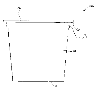
Turning now to these figures, Figure 1 is a side view of the beverage filter
cartridge
10 of the first embodiment of the present invention. The beverage filter
cartridge 10
00400523. DOC. } 16
CA 02785843 2012-08-09
includes a frustoconical sleeve 12, which, as will be shown below, is open at
its top and
bottom and has a larger diameter at the top than at the bottom. At the top of
the
frustoconical sleeve 12 is a flange 14, which extends outwardly around the
top. A cover 16
is sealed to the flange 14 to provide an oxygen barrier at the top of the
frustoconical sleeve
12. The cover 16 may be of a laminated foil material and is pierceable by an
inlet needle on
a beverage brewing apparatus. The cover 16 may be removable for recycling.
The frustoconical sleeve 12 also includes a shelf 24 having openings to enable
a
brewed beverage to drain therethrough. Among these openings are openings 26,
one for
each channel 22, which allow brewed beverage flowing along the channels 22 to
drain
quickly through the shelf 24. Other openings 28 allow brewed beverage seeping
from the
bottom of a filter pouch to drain through the shelf 24.
Figure 5 is an exploded cross-sectional view of the frustoconical sleeve 12
and
plug 18 shown in Figure 4. It will be noted that proximate to the flange 14 at
the top of the
frustoconical sleeve 12 and above the channels 22 is a smooth area 30 to which
the top of a
filter pouch is sealed. At the bottom of the frustoconical sleeve 12 is a bead
32 which is
provided to hold the plug 18 in place in a manner to be described below. Bead
32 extends
circumferentially around the inside of the bottom of the frustoconical sleeve
12, except
where interrupted by notches 20.
Figure 9 is a perspective view of a filter pouch 150. As shown, the filter
pouch 150
is generally cup-shaped, and does not have corrugations. Filter pouch 150 may
incorporate a
heat-sealable adhesive, so that the top portion 152 may be heat sealed to the
smooth area 113
on the inside of the frustoconical sleeve 112 proximate to the flange 114.
Filter pouch 150
preferably does not extend from smooth area 113 as far as the top surface of
the shelf 128 in
OO4OO523. DOC.) 17
CA 02785843 2012-08-09
Figures 3 and 4. Filter 150 is drawn without bulge section 151 as seen in
Figure 8 for ease or
representation and as an alternate approach. The filter 150 can be without the
bulge section
150 which reduces the flow but still allows the use of the channels 120 to
increase the
alternate flow paths.
Rather than having the vertically oriented channels 120, the inside of the
sleeve 112
may be provided with spiraling channels 153, as shown in Figure 10, or with
vertically
oriented channels 154, as shown in Figure 11. Alternatively, spiraling ridges
156 may be
provided on the inside surface of sleeve 112, as shown in Figure 12, or
vertically oriented
ridges 158, 160, as shown in Figures 13 and 14, with desired amounts of
spacing separating
them from one another. Instead of ridges 156, 158, 160, the inside surface of
sleeve 112
may be provided with bumps or moguls for the same purpose, namely, to ensure
that some
space will be available between the inside of the sleeve 112 and the filter
150 for the
drainage of a brewed beverage downward out of the sleeve 130.
It will thus be seen that the objects set forth above, among those made
apparent in the
preceding description, are efficiently obtained, and, since certain changes
may be made in
the above construction without departing from the spirit and scope of the
invention, it is
intended that all matter contained in the above description or shown in the
accompanying
drawings shall be interpreted as illustrative, and not in a limiting sense.
It is also understood that the following claims are intended to cover all of
the generic
and specific features of the invention herein described and all statements of
the scope of the
invention, which, as a matter of language, might be said to fall therebetween.
00400523. OC. } 18