Note : Les descriptions sont présentées dans la langue officielle dans laquelle elles ont été soumises.
CA 02785963 2012-06-28
WO 2011/081626 PCT/US2009/069811
Mobility-Enhancing Blood Pump System
TECHNICAL FIELD
This document relates to implanted medical pump systems, such as ventricular
assist pumps, and components, such as controllers and batteries associated
with the pump
systems.
BACKGROUND
The human heart is a complex and critical pump. Due to various pathologies,
the
heart can become dysfunctional, acutely or chronically. When damage to the
heart
becomes sufficiently symptomatic by clinical measures, the heart may be
diagnosed as
cardiomyopathic, a form of heart failure. In such a situation, a doctor can
recommend
mechanical assistance among the few therapeutic options that include
pharmacologic
therapy and heart transplantation. Where an afflicted person is scheduled to
receive a
transplant, mechanical assistance may be a choice of therapy until a donor
heart becomes
available.
Blood pumps are commonly used to provide mechanical augmentation to the
pumping performed by the left and/or right ventricles of the heart.
Ventricular assistance
may be provided by an implantable pump that is connected in parallel with the
person's
heart and may be regulated by a controller. The controller and the pump use a
power
source, such as one or more external batteries or electrical connection to a
wall socket. A
blood pump generally uses about 1-l OW of power. Connection to a sufficient
power
source to operate the pump and controller can make mobility difficult, which
can reduce
the quality of life for a patient.
SUMMARY
A blood pump system is described that includes a first implantable housing, an
implantable blood pump independent from the first implantable housing, and a
percutaneous extension. The first implantable housing includes a rechargeable
power
storage device. The implantable blood pump supplements the pumping function of
a
heart. The rechargeable power storage device supplies electrical power to the
implantable blood pump. The percutaneous extension is coupled to the
rechargeable
1
CA 02785963 2012-06-28
WO 2011/081626 PCT/US2009/069811
power storage device and adapted to traverse the skin. The percutaneous
extension is
configured to releasably connect to an external power supply adapted to
provide power
for recharging or supplementing the rechargeable power storage device to power
the
implantable blood pump.
The first implantable housing can have a volume that ranges from about 1 in3
to
about 20 in3. For example, the first implantable housing can have a volume
that ranges
from 7 in3 to 13 in3. In some embodiments, the implantable housing has a
volume of
about 10 in3. By having the first implantable housing independent from the
blood pump,
the housing can be sized to include a larger power storage device having a
larger power
storage capacity, which can extend the length of time that the blood pump can
be
operated with power supplied from the power storage device. In some
embodiments, the
rechargeable power storage device can supply electrical power for normal
operation of
the blood pump for a period of time of at least 30 minutes. In some
embodiments, the
rechargeable power storage device can supply electrical power for normal
operation of
the blood pump for a period of time of at least 2 hours. In some embodiments,
the
rechargeable power storage device can supply electrical power for normal
operation of
the blood pump for a period of time of at least 3.5 hours. In some
embodiments, the
rechargeable power storage device can supply electrical power for normal
operation of
the blood pump for a period of time of about 5 hours. In some embodiments, the
rechargeable power storage device can be recharged from a functionally
depleted state to
a fully charged state in less than about 1 hour.
The first implantable housing can further include an implanted telemetering
device. For example, the system further includes an external monitoring device
that
includes an external telemetering device that communicates wirelessly with the
implanted
telemetering device. In some embodiments, one of an internal system controller
and an
external monitoring device is adapted to notify the patient that an amount of
electrical
charge remaining in the rechargeable power storage device is less than a
minimum
threshold (e.g., by vibrating, by light, by sound). The minimum threshold can
be the
amount of electrical charge normally used for normal operation of the blood
pump, e.g.
30 minutes. In some embodiments, the first implantable housing is adapted to
vibrate to
2
CA 02785963 2012-06-28
WO 2011/081626 PCT/US2009/069811
notify the patient that the amount of electrical charge remaining is less than
the minimum
threshold.
The system can include two rechargeable power storage devices that supply
electrical power to the blood pump. The second rechargeable power storage
device can
be within the first implantable housing or, in other embodiments, within a
second
implantable housing. In some embodiments, a second implantable housing
encloses the
blood pump and includes pump controller circuitry that controls the operation
of the
blood pump. The system can include a rechargeable battery electrically
connected to the
pump controller circuit for supplying electrical power to the pump controller
circuit.
The percutaneous extension can include a plurality of wires that traverse the
skin
and carry electrical current to recharge or supply power to the rechargeable
power storage
unit. In some embodiments, the percutaneous extension has a cross-sectional
area that is
less than about 0.1 int. The percutaneous extension can also include an
electrical
connector coupled to the plurality of wires and adapted to couple to a portion
of the
external power supply. In some embodiments, the percutaneous extension
includes at
most four wires. In other embodiments, the percutaneous extension includes
more than
four wires. For example, the percutaneous extension can include two redundant
sets of
two wires, wherein each redundant set of wires can carry electrical current to
recharge the
rechargeable power storage unit.
The percutaneous extension can include a fluid-resistant sheath that is
coupled to
the electrical connector and that surrounds the plurality of wires along
substantially the
length of the plurality of wires. In some embodiments, the percutaneous
extension can
include a fluid resistant cap adapted to be removably coupled to the
electrical connector
for protecting the interior of the electrical connector from contact with
external fluids
when the electrical connector is not coupled to a portion of the external
power supply. In
some embodiments, the system includes an internal power sensing feature that
detects an
amount of power remaining in the rechargeable power storage device and a cap
or an
external end of the percutaneous extension is adapted to emit a light when the
power
sensing feature determines that the amount of power remaining in the
rechargeable power
storage device is less than a minimum threshold.
3
CA 02785963 2012-06-28
WO 2011/081626 PCT/US2009/069811
The system can include an internal system controller that controls the
operation of
the blood pump. In some embodiment, an internal system controller can be
included in
the first implantable housing.
The system can also include an external power supply. The external power
supply
can be, for example, a battery or a converted AC source. The external power
supply can
be adapted to supply electrical power for the normal operation of the blood
pump.
The blood pump can be a ventricular assist device (e.g., an LOAD).
The system can be implanted in a user and used for mechanical assistance to
the
user's heart and/or to replace the heart. The user can connect the
percutaneous lead to an
external power supply to supply power to the blood pump or to charge the
rechargeable
power storage device. The user can also disconnect the percutaneous lead from
the
external power supply for a period of at least 30 minutes, during which the
rechargeable
power storage device supplies power to the heart pump. The user can then
reconnect the
percutaneous lead to the external power supply to recharge the power storage
device or to
supply power to the blood pump.
In another aspect, the system includes an implantable blood pump that
supplements the pumping function of a heart, an internal system controller
that controls
the operation of the implantable blood pump, a rechargeable power storage
device that
supplies electrical power to the implantable blood pump and is adapted to
supply
electrical power for the normal operation of the implantable blood pump for a
period of
time of at least 30 minutes, and a percutaneous extension coupled to the
rechargeable
power storage device adapted to traverse the skin and to releasably connect to
an external
power supply to provide power to supplement or recharge the rechargeable power
storage
device. In some embodiments, the rechargeable power storage device has a
volume that
is greater than about 7 in3.
In another aspect, the system includes a first implantable housing including
an
internal system controller and a rechargeable power storage device, a blood
pump that
supplements the pumping function of a heart, and a percutaneous extension. The
first
implantable housing is coupled to the blood pump via one or more electrical
wires, and
the rechargeable power storage device supplies electrical power to the blood
pump for the
normal operation of the blood pump for a period of not less than 30 minutes.
The system
4
CA 02785963 2012-06-28
WO 2011/081626 PCT/US2009/069811
also includes an external device that wirelessly communicates with the
internal system
controller. The percutaneous extension is adapted to traverse the skin and to
releasably
connect to an external power supply to provide power to the rechargeable power
storage
device. The percutaneous extension includes two redundant sets of two wires.
Each
redundant set of wires is adapted to carry electrical current to recharge the
rechargeable
power storage unit. The percutaneous extension also includes an electrical
connector
coupled to the plurality of wires and adapted to couple to a portion of the
external power
supply. The percutaneous extension also includes a water-resistant sheath that
is coupled
to the electrical connector and that surrounds the plurality of wires along
substantially the
length of the plurality of wires. In some embodiments, the percutaneous
extension has a
cross-sectional area that is less than about 0.1 in2. In some embodiments, the
first
implantable housing has a volume that ranges from about 1 in3 to about 20 in3.
The blood pump system can be configured with features to decrease the
possibility of infection. The percutaneous lead can be configured to have a
smaller
diameter, thus lowering the possibility of infection around the skin opening
through
which the percutaneous lead passes. With a percutaneous lead that can be used
for
recharging the internal power storage devices, other more cumbersome power
transfer
methods, such as transcutaneous power transfer, can be avoided. Since
transcutaneous
power systems require the formation of large surgical pockets within the
patient to hold
the associated equipment, such as energy transferring coils, systems that do
not include a
transcutaneous power transfer system reduce the possibility of infection in
and
surrounding the pockets. Furthermore, systems that incorporate a percutaneous
lead for
power transfer advantageously reduce power losses during transfer and
eliminate tissue
heating, when compared to systems incorporating transcutaneous power transfer.
The details of one or more embodiments are set forth in the accompanying
drawings and the description below. Other features, objects, and advantages
will be
apparent from the description and drawings, and from the claims.
DESCRIPTION OF DRAWINGS
FIG. 1 is a front view depicting one embodiment of a mobility-enhancing hybrid
ventricular assist system implanted in a patient and an external communication
device.
5
CA 02785963 2012-06-28
WO 2011/081626 PCT/US2009/069811
FIG. 2 is a front view depicting one embodiment of a mobility-enhancing hybrid
ventricular assist system implanted in a patient, the hybrid system including
a blood
pump, a controller, rechargeable power storage devices, and a compact
percutaneous
lead.
FIG. 3A is schematic representation of one embodiment of a mobility-enhancing
hybrid ventricular assist system including a controller assembly and a power
storage
assembly, each separate from the blood pump.
FIG. 3B is schematic representation of another embodiment of a mobility-
enhancing hybrid ventricular assist system connected to an external power
source.
FIG. 4 is a cross-sectional view of one embodiment of a compact percutaneous
lead with two sets of redundant power leads.
FIG. 5 is a schematic representation of one embodiment of an implantable
controller with two unequal capacity rechargeable storage devices.
FIG. 6 is a schematic representation of one embodiment of a mobility-enhancing
hybrid ventricular assist system including a blood pump, a controller,
rechargeable power
storage devices, and a compact percutaneous lead.
FIG. 7 depicts a front view of one embodiment of a mobility-enhancing hybrid
ventricular assist system implanted in a patient with the hybrid system
connected to an
external controller and external batteries contained in a carrier system.
FIG. 8 depicts a front view of one embodiment of a mobility-enhancing hybrid
ventricular assist system implanted in a patient with the hybrid system
connected to
external batteries contained in a carrier system and in wireless communication
with an
external interface.
Like reference symbols in the various drawings indicate like elements.
DETAILED DESCRIPTION OF ILLUSTRATIVE EMBODIMENTS
An exemplary hybrid blood pump system generally includes a blood pump, at
least one internal rechargeable power storage device, and a percutaneous lead.
The
hybrid blood pump system is configured to enhance the freedom and mobility of
the user
by allowing for normal function of the blood pump when the user is
disconnected from
an external power source. The internal rechargeable power storage device can
store
6
CA 02785963 2012-06-28
WO 2011/081626 PCT/US2009/069811
sufficient power to provide for the normal operation of the blood pump for an
extended
period of time (e.g., at least about 30 minutes and ideally at least 2 hours).
The
percutaneous lead allows for the percutaneous transfer of power from an
external source
to normally operate the blood pump and to recharge the internal power storage
device.
The hybrid system, which can run on power supplied by either an internal
rechargeable
power storage device, or by a direct connection with an external power source
via the
percutaneous lead, provides a system that allows for increased mobility while
avoiding
problems associated with fully implanted systems that transfer power
transcutaneously.
Exemplary hybrid systems are described below in connection with the attached
figures.
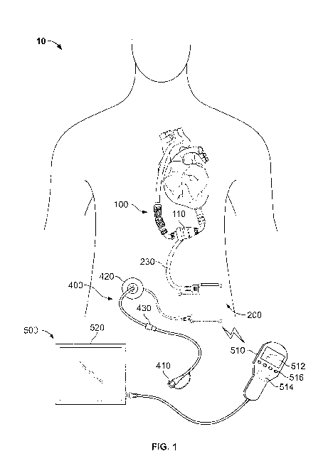
FIG 1 is a front view depicting an example of a mobility-enhancing hybrid
ventricular assist system 10 including an internal blood pump assembly 100, an
internal
controller assembly 200 connected to the blood pump assembly via an electrical
conduit
230, internal rechargeable power storage device(s) 350 contained within the
controller
assembly 200 (see FIG. 2), and a percutaneous lead 400 connected to the
controller
assembly 200 and exiting the body. The power storage device(s) 350 include one
or more
"smart" lithium-chemistry batteries that are readily rechargeable. An external
monitoring
device 500 can perform wireless 2-way communication with the internal
components of
the hybrid system 10, for example, via wireless telemetry device 220 (see FIG.
2). FIG. 2
is a close-up of the system of FIG. 1, not showing the external monitoring
device 500 but
showing exemplary internal components of the controller assembly 200. As
depicted in
FIG. 1, the internal pump assembly 100 can also include an implantable blood
pump 110
fluidly connected to an internal chamber of a heart and circulatory system,
and a
programming wand 510 included in the external monitoring device 500 for
communication with the controller assembly 200. The programming wand can
include a
built-in display 512 for displaying menus, data, and the like, and a external
wireless
telemetry device 514 for communicating with the internal telemetry device 220
and one
or more user-selectable buttons 516 (e.g., four buttons in this embodiment).
Blood Pump
The blood pump 110 can be a ventricular assist device (VAD). A VAD is a
mechanical circulatory device that is used to partially or completely replace
the function
7
CA 02785963 2012-06-28
WO 2011/081626 PCT/US2009/069811
of a failing heart. Some VADs are intended for short term use, typically for
patients
recovering from heart attacks or heart surgery, while others are intended for
long term use
(e.g., months, years, and the remainder of a user's life), typically for
patients suffering
from congestive heart failure. VADs are designed to assist either the right
(RVAD) or left
(LVAD) ventricle, or both at once (BiVAD). VADs can be designed with an axial
flow or
centrifugal flow configuration. The former can be configured with an impeller
suspended
by journal bearing such as a ball and cup, or by magnetic or hydrodynamic
forces. The
latter can be configured with an impeller suspended by at least magnetic
forces,
hydrodynamic forces, or a combination of both. In other embodiments, the blood
pump
can be an artificial heart, which is designed to completely take over cardiac
function and
may require the removal of a patient's heart. It should be appreciated that
the technical
features disclosed herein apply equally to any variation of the blood pump as
described in
this disclosure.
As depicted in FIG. 1, a hybrid ventricular assist system 10 can include the
internal pump assembly 100 connected in parallel with the left ventricle of a
heart such
that the pump assembly 100 can mechanically augment the pumping of blood
performed
by the left ventricle. In particular, FIGS. 1 and 2 depict the internal pump
assembly 100
including the blood pump 110, such as the HeartMate II LVAD, a product of the
Thoratec Corporation of Pleasanton, California, while FIGS. 7 and 8 depict
the pump
assembly 100 that includes a different embodiment of an LVAD. For example, the
pump
assembly 100 can be installed to temporarily provide mechanical assistance
while an
individual waits for a transplant. In other examples, the pump assembly 100
can be
implanted to reduce the stress on a person's heart, allowing it to heal and
regain normal
function, and later be removed. In yet other examples, the pump assembly 100
can be
implanted as a substantially permanent option.
The blood pump can include internal pump control circuitry. Internal pump
control circuitry can also be included in a separate housing (e.g., with
internal
rechargeable power storage device). Internal pump control circuitry functions
to make
the blood pump pump when power is supplied to the blood pump and is distinct
from a
controller that may alter the pumping operation, alter how power is being
supplied to the
blood pump and/or perform other functions for the system, such as detecting
whether the
8
CA 02785963 2012-06-28
WO 2011/081626 PCT/US2009/069811
system is being provided with power from an external power source and
detecting
whether the internal rechargeable power source needs to be recharged from the
external
power source.
Internal Power Storage Device(s)
One or more power storage devices 350 can be included in a single housing. In
some embodiments, this single housing also includes a controller device 210.
As
depicted in FIGS. 1, 2, and 3B, a controller device 210 and the power storage
device(s)
350 can be within the single controller assembly 200. As depicted in FIG. 2, a
controller
assembly can include two (or more) power storage devices 350. In other
embodiments,
the controller assembly can include a single power storage device, or any
number of
power storage devices. In still other embodiments, such as depicted in FIGS.
3A, 7, and
8, the hybrid system 10 can include one or more housings, separate from the
controller
assembly, each containing one or more power storage devices.
As depicted in the FIGS. 1 and 2, the power storage device(s) 350 can be
implanted in a location separate from the blood pump assembly 100, for
example, in the
thorax or the abdomen of a patient. In particular examples, the housing can be
implanted
in the abdominal quartet, below the thorax, within the mussel layers. In other
embodiments, the power storage device(s) 350 can be implanted in other body
locations,
such as within the leg of a patient. A housing containing the power storage
device(s) 350
can be positioned and shaped to maximize the dissipation of heat from the
power storage
device(s) 350. For example, the housing can be positioned to maximize the
amount of
blood circulating around the housing. Accordingly, it can be advantageous to
implant the
housing containing the power storage device(s) 350 at or near the core of the
patient.
Implanting the power storage device(s) 350 within a housing in a location
separate from
the blood pump assembly 100 can allow for the use of a larger power source
than can
normally be accommodated within the blood pump assembly. It can be desirable
to limit
the volume of devices implanted adjacent to the heart. As such, a battery
implanted
inside or in close proximity to a blood pump assembly 100 is limited in size,
and thus
electrical capacity. To allow for a longer period of time in which the user is
not
connected to an external power source, the power storage device(s) can be
9
CA 02785963 2012-06-28
WO 2011/081626 PCT/US2009/069811
advantageously included in a location separate from the blood pump assembly.
Locations
such as the abdomen may be able to accept larger implanted devices, and thus
allow for
larger power storage device(s), which can be used to increase the period of
time that the
internal blood pump can function normally without being coupled to an external
power
source. Moreover, having the power storage device(s) 350 in a location
separate from the
blood pump assembly 100 can reduce the probability of heat from the internal
power
storage device(s) damaging the heart and/or tissue adjacent the heart.
Furthermore, a
location of the power storage device separate from the blood pump assembly
allows for
outpatient replacement of the power storage device, if necessary. Thus, a
location can
also be selected in accordance with the level of ease in which the power
storage device
can be replaced.
The total volume of the power storage device(s) 350 can be 1 in3 or greater.
In
some embodiments, the total volume of a housing including the power storage
device(s)
is between about 1 in3 and about 20 in3. In some embodiments, the power
storage
device(s) are designed with various options based on size and run time,
including but not
limited to providing greater than 30 minutes of blood pump normal operation,
greater
than 1 hour of blood pump normal operation, greater than 2 hours of blood pump
normal
operation, and greater than 3.5 hours of blood pump normal operation. The
housing can,
in preferred embodiments, have a volume of between 5 in3 and 13 in3 (e.g.,
about 10 in3).
The total volume of a housing would also depend on the material used and the
battery
technology. Generally, there is a tradeoff between size and run time. For
instance, the
larger the rechargeable power source the larger the charge storage capacity
and thus the
longer the run time. However, there is also a higher risk of infection. On the
other hand,
the smaller housing containing a smaller rechargeable power source would have
a smaller
charge storage capacity, a shorter run time, but a lower risk of infection.
The housing, like most implanted components, can be hermetically sealed. The
housing can be made of commercially available inert materials including both
biocompatible metals, biocompatible polymers, and biocompatible ceramics, such
as
stainless steel, titanium and titanium alloys (e.g., Ti-6A1-4V grade 5
titanium), cobalt-
chromium alloys, polyethylene (e.g., UHMWPE), PEEK polymers, and combinations
thereof. The housing material can also be selected for its ability to
dissipate heat as well
CA 02785963 2012-06-28
WO 2011/081626 PCT/US2009/069811
as its ability to provide an electrical and/or magnetic shield should it be
used to house an
internal controller. The housing can be substantially flat. For example, the
housing can
have a thickness of about 0.3 to 1 inch, a width of about 1.5 to 3.5 inches,
and a length of
about 3 to 6 inches. In some embodiments, the housing has dimensions
approximating
the dimensions of a standard cigarette pack (about 2.6 inches x about 4.6
inches x about
0.6 inches). In some embodiments, the housing can have a slightly curved
configuration
bent to confirm to the contours of a human abdomen, similar to a whisky flask.
The
housing can also have rounded corners. This can allow a user to have increased
freedom
of movement because batteries of this volume can be used to provide power for
normal
pump operation for extended periods of time without the use of an external
power supply.
A flat configuration can allow for a more superficial placement and
replacement, if
necessary. A flat configuration can also facilitate the dissipation of heat.
The housing
can also have rounded corners and other features to reduce injury to
surrounding tissue.
An outer surface of the housing can having a coating or other features that
reduce the
instances of pocket infection.
As the pump is directly connected to the heart, the size of the implant
adjacent to
the heart should be minimized. As the size of the implant increases, so does
the risk of a
pocket infection. If the pump pocket becomes infected, the infection could
enter the
blood stream causing sepsis, which can be extremely hazardous to an already
immuno-
compromised patient. An implant of minimal size adjacent to the heart can
allow for
placement of the device entirely within the thorax which may simplify the
surgery and
allow for a shorter recovery time.
The power storage device(s) 350 can be one or more rechargeable batteries. For
example, the power storage device(s) 350 can be one or more lithium ion
batteries. In
other embodiments, the power storage device(s) 350 can be one or more lithium
polymer
batteries. In other examples, the power storage device(s) 350 may comprise a
capacitor
device capable of being recharged over time and discharging power sufficient
for normal
operation of the system 10. Still, fuel cell technology using hydrogen as an
energy
storage vehicle may provide a viable option, using electricity provided by an
external
power source to electrolyze water within the body to generate additional
hydrogen. Still,
11
CA 02785963 2012-06-28
WO 2011/081626 PCT/US2009/069811
other high density power storage devices may be developed in the future and
can be used
in as the power storage device(s) 350 as described herein.
Because some batteries may become non-rechargeable if fully depleted, some
batteries, such as "smart" lithium-polymer batteries, can include internal
circuitry that
prevents the batteries from becoming fully depleted. As such, if the charge
level within
such a battery falls below a predetermined level, this internal circuitry can
cause the
battery to stop delivering power to avoid irreversibly damaging the battery.
Accordingly,
if the charge within a battery falls below this predetermined level, the
battery is
functionally depleted. As an alternative, the controller device 210 can
determine whether
the energy remaining in a particular power storage device 350 has fallen below
a
predetermined threshold and can stop transferring power from a power storage
device
350 if the remaining energy falls below that predetermined threshold. Still,
another
possibility is to have the controller device 210 send a warning signal when
the power
capacity drops below a certain level and into a range where operation of the
pump is still
possible, but before it is considered functionally depleted.
When connected to an external power source, the internal power storage devices
350 can be recharged using energy from the external power source. Charge time
can
depend on the size of the battery and the charge rate limitations for heat
dissipation in the
charge electronics and the heat dissipation in the percutaneous lead. For
example, power
storage devices can be recharged in 50% to 400% of the discharge time. In some
embodiments, the internal power storage devices can be recharged from a
functionally
depleted state to having a full charge in less than 30 minutes.
Percutaneous Lead
As shown in FIGS. 1 and 2, the percutaneous lead 400 can include a proximal
end
402 located internal to the user and a distal end 404 located external to the
user, with a
portion 406 that traverses the skin. The proximal end 402 can be electrically
connected
to the controller assembly 200 and the distal end 404 can be removably coupled
to an
external power supply (not shown). A cap 410 can be used to protect the
external
physical structure of the distal end 404 and connector, as well as the exposed
metal
connections that can be coupled to the external power supply. In some
embodiments, this
12
CA 02785963 2012-06-28
WO 2011/081626 PCT/US2009/069811
cap can be designed to be fluid resistant (or fluid proof). In some
embodiments, the cap
can prevent moisture from seeping into the connector and reaching the metal
connections.
The cap can also to prevent any electrical conduction from any outside element
with the
metal connections. In some embodiments, the cap can be waterproof and fluid
resistant.
The cap structure can be made of a metallic or non-conducting material; in
either case,
the cap design will have insulation to prevent shorting of the metal
connections or
conduction of electricity between an external source and the metal
connections. When
connected to an external power supply, power sufficient for the normal
operation of the
hybrid system 10 and to charge the power storage device(s) 350 can be
transferred
through the percutaneous lead 400 by redundant power and ground lines. When
the
percutaneous lead is disconnected from an external power supply, power for the
normal
operation of the hybrid system 10 can be supplied by the internal rechargeable
power
storage device(s) 350.
The distal end 404 of the percutaneous lead 400 can be electrically coupled to
an
external power source. In these circumstances, the external power source can
supply
power for normal operation of the internal components of the hybrid system 10
(e.g., the
pump assembly 100, the controller assembly 200, and the like) and to recharge
the power
storage device(s) 350. The external power source can be in the form of
external batteries,
an external power source plugged into a traditional wall socket such that it
can convert
AC electricity to DC electricity, and the like. For example, when the
percutaneous lead
400 is coupled to an external power source that is plugged into a wall socket,
the user is
limited in the distance that he can travel. In these circumstances, the user
may be limited
to a single room, a single building, and the like. Furthermore, due to the
connection of
the percutaneous lead 400 to the external power source, the user may be
limited from
performing activities requiring a high degree of freedom of physical movement
and/or
that involve exposure to liquids, including but not limited to daily
activities such as
taking a bath, grocery shopping, physical and sporting activities like
swimming, golf,
tennis, etc., and household maintenance.
To increase a user's freedom of movement, the hybrid ventricular assist system
10
can be configured to be electrically coupled via the percutaneous lead 400 to
a portable
external power source, such as external batteries. For example, FIGS. 7 and 8
depict a
13
CA 02785963 2012-06-28
WO 2011/081626 PCT/US2009/069811
portable system for carrying external batteries. When the percutaneous lead is
connected
to a portable external power source, the user can experience improved
mobility, comfort,
independence, and self-esteem when compared to being coupled to a power source
plugged into a wall socket. For example, the user can wear a garment that is
designed to
contain rechargeable batteries such that the user is free to perform household
chores,
travel to the grocery store, go on a walk, etc. When coupled to external
batteries worn as
part of a garment, a user is not restricted by a cord plugged into a wall and
is free to
partake in many normal day-to-day activities, thus leading to increased
independence and
self-esteem. Additionally, since the external power source is worn with the
user, the
possibility of pulling on the percutaneous lead and damaging surrounding
tissue is
reduced, leading to a decreased possibility of infection and increased
comfort.
To further increase a user's freedom of movement, the hybrid ventricular
assist
system 10 can be used for extended periods of time without the use of an
external power
supply. For example, when a user desires to have a greater freedom of movement
and
comfort, the user can disconnect the distal end 404 of the percutaneous lead
400 from an
external power source, thus freeing him from the limitations imposed by such
an external
power source. While disconnected from the external power source, the internal
power
storage device(s) 350 can supply the power for the normal operation of the
hybrid system
10 (e.g., the pump assembly 100, the controller assembly 200, and the like)
for an
extended period of time (e.g., greater then 30 minutes, greater than 1 hour,
greater than 2
hours, greater than 3.5 hours, and the like, based on the size and capacity of
the internal
power storage device 350). While unplugged from all external power sources,
the user
experiences greater freedom to take part in physical and passive activities,
such as
swimming and bathing, that would otherwise be complicated by external cords,
batteries,
and the like.
When the percutaneous lead 400 is reconnected to an external power source, the
external power source can be used to not only support normal operation of the
hybrid
system 10, but also to recharge the internal power storage device(s) 350.
Using the
percutaneous lead 400 to transfer energy from an external power source allows
for a
greater power transfer efficiency, and thus faster recharge rate, than a
transcutaneous
power transmission system. In some embodiments, the internal power storage
device(s)
14
CA 02785963 2012-06-28
WO 2011/081626 PCT/US2009/069811
can be advantageously recharged from a functionally depleted state to a fully
recharged
state in less than 30 minutes.
As previously referenced, a blood pump system can use a transcutaneous power
system to wirelessly transfer power from an external power source to
components
implanted in a user. For example, power can be transmitted from the external
source to
the internal components by generating a magnetic field in the external coil
and converting
the magnetic field to electrical power in the internal coil, which is
distributed to the other
internal components. However, transcutaneous power systems can be limited in
the rate
of power transferred, for example, by the size of the coils. To increase the
rate at which
lo the power storage device(s) are charged, larger coils can be used. However,
larger coils
occupy additional internal space, which can result in an increased possibility
of infection,
and can result in the user carrying additional external equipment. Smaller
coils, however,
have slower transfer rates. Furthermore, transcutaneous power transmission can
lose
power during transmission, some of which is lost as heat within the tissues
separating the
internal and external transmission coils. This heating can be damaging to
tissue.
Additionally, due to energy lost during transmission, a user wearing external
batteries,
each with a fixed energy capacity, would have less time in between battery
changes when
using a transcutaneous power transfer system when compared to transferring
power via
the percutaneous lead 400. Also, fixation of the coils is critical for
maintaining optimal
alignment. As the coils become more decoupled (i.e. through misalignment
and/or
separation), efficiency of the transfer drops.
The percutaneous lead 400 can, in some embodiments, have a cross sectional
area
of less than about 0.10 square inches (e.g., a diameter that is less than
about 0.3 inches).
When using a reduced-diameter percutaneous lead 400, a smaller opening in the
user's
skin is used to accommodate the percutaneous lead 400. Reducing the diameter
of the
percutaneous lead that traverses the skin of the user has the beneficial
effect of exposing
less tissue, thus decreasing the possibility of infection around this opening.
While a
larger diameter percutaneous lead can increase transfer of both power and data
to the
internal components, a reduction in the diameter of the percutaneous lead can
be achieved
by using the percutaneous lead to only transfer power. The use of highly
conductive
materials in the percutaneous lead can be used to offset the smaller diameter,
or the
CA 02785963 2012-06-28
WO 2011/081626 PCT/US2009/069811
reduced cross-sectional capacity of the conductors. Accordingly, in some
embodiments,
control data is transmitted via wireless communication, thus allowing for a
reduction in
the diameter of the percutaneous lead 400. In comparison, exemplary
percutaneous leads
that include redundant sets of wires for transferring both power and data can
have
diameters that exceed 0.75 inches in diameter. In other embodiments, for
example in
ventricular assist systems lacking an internal controller device 210, a larger
diameter
percutaneous lead may be used to reliably transfer both power and data to the
internal
components. In these examples, the percutaneous lead can have a diameter that
is greater
than 0.5 square inches (e.g., greater than 0.75 inches in diameter).
FIG. 4 is a cross-sectional view of a compact percutaneous lead 400 with two
sets
of redundant power leads. The percutaneous lead 400 can include a flexible
outer
housing 408 enclosing redundant electrical lead sets 440 and 445, for example
as
discussed in U.S. Patent Application 12/472,812, filed May 27, 2009, which is
hereby
incorporated by reference. In this configuration, electrical energy can be
supplied from
an external power source to the internal components of the hybrid ventricular
assist
system 10 (e.g., the blood pump 110, the controller device 210, the power
storage
device(s) 350, and the like). Each of the lead sets 440 and 445 can be capable
of
transferring all of the power for normal operation of the hybrid system 10,
including
recharging of the power storage device(s) 350, resulting in fully redundant
energy
transfer. Thus, if one of the conductors of one of sets 440 and 445 becomes
damaged
such that it is unable to transfer electrical energy, the system 10 can be
fully powered by
the one set 440 and 445 that remains intact. Furthermore, if one conductor of
each set is
damaged, power can be transferred by using non-damaged conductors from each
set In
examples where the percutaneous lead 400 contains only the lead sets 440 and
445 for
transferring energy, the percutaneous lead 400 has a smaller cross-sectional
area than in
cases where additional wires are included for data transfer.
The cross-sectional area of the percutaneous lead 400 can be further decreased
by,
for example, including only a single set of power transfer wires. In other
examples, the
cross-sectional area of the percutaneous lead 400 may be decreased by
decreasing the
diameter of the lead sets 440 and 445 (e.g., by configuring them such that
they are not
fully redundant). In this example, each lead set 440 and 445 may be configured
to carry
16
CA 02785963 2012-06-28
WO 2011/081626 PCT/US2009/069811
only a percentage (e.g., less than 100%, 95%, 64%, 50%, and the like) of the
total energy
used during normal operation of the system 10 and recharging of the power
storage
device(s) 350. For example, each lead set 440 and 445 may be configured to
supply
sufficient power for normal operation of the hybrid system 10 and to trickle
charge the
power storage device(s) 350. In this example, when both lead sets 440 and 445
are
functional, the hybrid system 10 can be supplied with power for normal
operation and
with sufficient power such that the power storage device(s) 350 can be quickly
charged
(e.g., the power storage devices can be recharged in less than 60 minutes). In
other
embodiments, the system can have a longer recharge time, depending on the type
of
power storage device and the percutaneous lead. However, if one of the lead
sets 440 and
445 becomes non-functional (e.g., the lead set is damaged and becomes unable
to
transmit power), the system 10 can operate normally with the exception of
charging the
internal power storage device(s) 350, which will be accomplished at a slower
rate. In this
example, a redundancy is provided for normal operation of the system 10 while
further
reducing the diameter of the percutaneous lead 400, thus further decreasing
the
possibility of infection.
The hybrid ventricular assist system 10 can include other features that
decrease
the cross-sectional area of the percutaneous lead 400 while allowing for power
and data
transfer through the lead 400. For example, the lead 400 can include the lead
sets 440
and 445 configured to transfer power from a power source external to a user to
the
internal components of the system 10. Power transferred from an external power
source,
for example, can be used for normal operation of the blood pump 110 and to
recharge the
internal power storage device(s) 350. Since power for the normal operation of
the
internal components of the system 10 can come from the power storage device(s)
350,
power transfer can be temporarily discontinued through one or more of the lead
sets 440
and 445, thus leaving one or more of the lead sets 440 and 445 available for
the transfer
of data. When the data transmission is complete, power once again can be
transferred
through the lead sets 440 and 445. This feature for the temporary cessation of
power
transfer can be incorporated into other percutaneous lead configurations, can
be
combined with other lead-size-reducing features, and is not restricted to the
four-wire
percutaneous lead depicted in FIG. 4. In some embodiments, the percutaneous
lead
17
CA 02785963 2012-06-28
WO 2011/081626 PCT/US2009/069811
includes two non-redundant sets of wires, one set for charging the power
storage
device(s) 350 and one set for providing power to the blood pump. In such an
embodiments, a disabled recharging set can be rerouted to simply provide power
to the
blood pump.
FIG. 6 is a schematic representation of the mobility-enhancing hybrid
ventricular
assist system 10 including the blood pump assembly 100, the controller
assembly 200,
the rechargeable power storage devices 350 and 355, and the compact
percutaneous lead
400. The hybrid system 10 can be configured to reduce the diameter of the
percutaneous
lead 400. In some embodiments, the hybrid system 10 includes internal
controller
assembly 800 that can control functions of the hybrid system 10 and can
wirelessly
communicate with external components. Due at least in part to the presence of
the
internal controller assembly 800, data communication between the internal
controller
assembly 800 and external components can be transmitted in a manner other than
through
the percutaneous lead 400. Since the percutaneous lead 400 can be limited to
the transfer
of electrical energy, the resulting diameter of the percutaneous lead 400 can
be smaller
than if data transfer also took place through the percutaneous lead 400. For
example, the
controller device 210 can be electrically connected to the two power storage
device(s)
350 and 355 with lead sets 860 and 861, respectively, and to the wireless
telemetry device
with redundant data lead sets 862 and 863. Furthermore, the controller device
210 can be
electrically connected to the pump assembly with two redundant power lead sets
864 and
865 and two redundant data lead sets 866 and 867. In this example, the
internal
controller 210 is electrically connected to the pump assembly 100 by eight
wires, but
only four wires are used in the percutaneous lead 400. In examples where a
controller
device is external to the patient, additional wires may be used in the
percutaneous lead
that traverses the skin of the user.
The percutaneous lead 400 can additionally include other features that reduce
a
user's possibility of infection. As described above, an opening in the skin
exposes tissue
to infection. Additionally, movement of the portion 406 of the percutaneous
lead 400 that
traverses the skin opening in relation to the skin opening itself can cause
damage to tissue
surrounding the percutaneous lead 400, thus increasing the possibility of
infection. The
hybrid system 10 can be configured to include features that reduce movement of
the
18
CA 02785963 2012-06-28
WO 2011/081626 PCT/US2009/069811
internal portion of the percutaneous lead 400 relative to the user. For
example, as
depicted in FIGS. 1 and 2, the percutaneous lead 400 can include a strain-
relief portion
420 for anchoring the percutaneous lead 400 to the user and for reducing the
strain on the
portion of the percutaneous lead exiting the user's body. In another example,
the
percutaneous lead 400 can include a low-force breakaway portion 430 that can
separate
when subjected to a pulling force that is less than the force expected to
cause damage to
the tissue surrounding the skin opening. Due to the presence of the internal
power
storage device, the percutaneous lead does not act as a lifeline, thus a
breakaway
connection can be used because an accidental disconnection will not result in
a loss of
power to the blood pump. When the distal end 404 of the percutaneous lead 400
is pulled
with a force greater than the break-away force of the breakaway portion 430,
the
percutaneous lead 400 can reversibly separate into two portions, thus reducing
the strain
on the portion of the percutaneous lead 400 entering the skin opening. The two
portions
can be re-joined at the breakaway portion 430 when the stress on the breakaway
portion
430 falls below the break-away force. While the percutaneous lead 400 is
separated into
the two portions, sufficient power to maintain normal operation of the hybrid
system 10
can be supplied by the internal power storage device(s) 350. When the
percutaneous lead
400 is reconnected, power to maintain normal operation of the hybrid system 10
can once
again be supplied by the connected external power source, while also
recharging the
internal power storage device(s) 350.
The percutaneous lead can be connected to the external power source by use of
a
connector. For example, the connector can be flat, square, round, or any other
shape.
The connector can provide a fluid resistant or fluid proof connection. In some
embodiments, the connector can prevent liquid water proof and water vapor
proof.
Controller
The blood pump can be controlled by internal control circuitry. In some
embodiments, the control circuitry can be a part of the blood pump assembly
100. In
other embodiments, the control circuitry (e.g., controller device 210) can be
within the
same housing containing the rechargeable power storage device(s) 350, as
depicted in
FIGS. 1, 2, and 3B. In other embodiments, control circuitry can be within a
dedicated
19
CA 02785963 2012-06-28
WO 2011/081626 PCT/US2009/069811
implantable housing separate from both the blood pump assembly 100 and the
housing
containing the rechargeable power storage device(s) 350, as depicted in FIGS.
3A, 7, and
8. Internal control circuitry (e.g., the controller device 210) can in some
embodiments
communicate with an external controller and/or an external input device.
The internal control circuitry can include, but is not limited to, one or more
features to monitor the operation of the hybrid ventricular assist system 10,
to monitor the
user (e.g., to detect blood pressure), to control predetermined functions of
the hybrid
system 10 (e.g., to control how power is supplied to the blood pump), and to
inform the
user of particular information regarding operation of the hybrid system 10
(e.g., by
vibrating or by sending a signal to an external device). The internal control
circuitry can
include features for controlling the speed of the pump 110. In another
example, the
internal control circuitry can monitor functions of the system 10, such as the
electrical
charge level of (i.e. usable energy remaining in) the power storage device(s)
350. In still
another example, the internal control circuitry can inform the user of alerts
and alarms
pertaining to the operation of the hybrid system 10, such as alerting the user
when the
charge level of one or more of the power storage devices 350 has fallen below
a
predetermined threshold, or signaling an alarm when a malfunction in the
system 10 has
occurred. The internal control circuitry can inform the user of a condition,
for example,
by initiating an internal vibrator, signaling a remote controller via the
wireless telemetry
unit 220, causing a light to flash, and the like. For example, in some
embodiments, an
external portion of the percutaneous lead 400 (e.g., the cap 410, the distal
end 404 of the
percutaneous lead 400, and the like) can include a light that can flash. For
example, if the
amount of power remaining in the internal power supply falls below a threshold
and
power is not being supplied to the system through the percutaneous lead, the
controller
can direct power though wires provided in the percutaneous lead 400 to a light
in an
external portion of the percutaneous lead or in the cap. In yet another
example, the
controller can monitor the inlet and outlet pressures of the pump 110,
determine blood
flow through the pump assembly 100, determine an activity level of the user
and thereby
change the speed of the pump, and the like. These controller functions can
also be
preformed using an external controller that communicates with the internal
controller, for
example using an external communication device that performs wireless 2-way
CA 02785963 2012-06-28
WO 2011/081626 PCT/US2009/069811
communication. The controller can also detect whether power is being provided
through
the percutaneous lead and to control whether that power is used to simply
operate the
blood pump or to also recharge the internal power supply. The internal
controller can
also include electrical circuitry to detect and shut down (if necessary)
failed conductors in
the percutaneous lead and/or between the controller and blood pump or other
internal
housings. This can be accomplished by detecting increased or decreased
electrical
resistance. In some embodiments, the controller can then use a redundant
conductor. The
controller can also provide different alarms depending on whether power is
being
supplied via the percutaneous lead, and in some embodiments depending on which
external power source is active (e.g., external portable battery versus
converted AC
power source). Internal alarms can include internal vibrators (e.g.,
piezoelectric buzzers).
External alarms can include lights and/or audible alarms.
The controller can also include a memory buffer to store information. The
member buffer can store acquired data, such as pump speed and physiological
data of the
patent (e.g., blood pressure). The member buffer can also be used to record
information
about how the pump system is operating, including error information and/or
battery life.
The information in the memory buffer can be downloaded to an external system
via the
percutaneous lead and/or via a telemetry system. The memory buffer can provide
a
means to record information when the user is disconnected and/or away from
external
components.
External Components
The hybrid ventricular assist system 10 can be electrically coupled via the
percutaneous lead 400 to an external power source that can supply power for
normal
operation of the hybrid system 10. The external power source can be external
batteries, a
wall socket, or the like. An external power source can have different levels
of
technological complexity, ranging from a simple AC transformer/adapter to a
control
console that is used to diagnose, control, and/or modify functions of the
pump. In some
embodiments, the external batteries can be part of or connected to an external
controller,
as depicted in FIG. 7. In other embodiments, such as depicted in FIG. 8, the
percutaneous
lead 400 can be directly connected to external batteries. Power supplied by
the external
21
CA 02785963 2012-06-28
WO 2011/081626 PCT/US2009/069811
power source can be used to recharge the power storage device(s) 350. As noted
above,
the hybrid system 10 can also include an external controller (e.g., an
external controller
500) that can be used in conjunction with or in lieu of the internal
controller device 210.
Referring again to FIG. 1, the hybrid ventricular assist system 10 can include
the
external monitoring device 500 in wireless communication with the internal
components
of the hybrid system 10 (e.g., the controller device 210, the wireless
telemetry device
220, the pump assembly 100, and the like). The external controller 500 can
include the
programming wand 510. The programming wand can include the built-in display
512 for
displaying menus, data, and the like, the external wireless telemetry device
514 for
communicating with the internal telemetry device 220, and the one or more user-
selectable buttons 516 (e.g., four buttons in this embodiment) for navigating
menus,
selecting features, inputting data, and the like.
The external electrical interface can include electronics to detect and shut
down
(if necessary) any faulty conductors in the percutaneous cable.
Schematics
FIG. 3A is schematic representation of one embodiment of the mobility-
enhancing
hybrid ventricular assist system 10 including a controller assembly 600 and a
separate
power storage assembly 300. As depicted in FIG. 3A, the hybrid system 10 also
includes
the internal blood pump assembly 100, one or more rechargeable storage devices
(e.g.,
the power storage device 350, and the like) included in the power storage
assembly 300,
and the compact percutaneous lead 400. The controller assembly 600 can be
implanted
in, for example, the thorax, the abdomen, or other parts of a patient and can
be
electrically connected to the pump assembly 100 via the electrical conduit 230
such that
the controller assembly 600 can control functions of and monitor the pump
assembly 100.
The controller assembly 600 can be connected to the power storage assembly 300
via an
electrical conduit 330 and can control charging of the power source contained
within the
power storage assembly 300. Power for normal operation of the hybrid system 10
can be
supplied by the power storage assembly 300. The power storage device 350, for
example, can be directly electrically connected to the controller assembly
600, the pump
assembly 100, and the like, and can be implanted in the thorax, the abdomen,
or other
22
CA 02785963 2012-06-28
WO 2011/081626 PCT/US2009/069811
parts of the user in a location separate from those of the controller assembly
600 and the
pump assembly 100. In other embodiments, the power storage device 350 may
indirectly
provide power to the pump assembly 100. Power storage devices, in addition to
or in lieu
of the power storage device 350, can be included in one or both of the blood
pump
assembly 100 and the controller assembly 600.
FIG. 3B is a schematic representation of certain embodiments of the mobility-
enhancing hybrid ventricular assist system 10 connected to an external power
source 20.
The hybrid system 10 can include features that allow for power to and control
of an
internal pump without constant connection to external devices. For example,
the hybrid
system 10 can include the internal controller assembly 200 that includes the
controller
device 210, the wireless telemetry device 220, and the two rechargeable power
storage
devices 350 and 355. The controller assembly 200 can be implanted in a single
location
(e.g., in the thorax, the abdomen, and the like) with the electrical conduit
230 electrically
connecting elements contained within the controller assembly 200 (e.g., the
controller
device 210, the wireless telemetry device 220, the rechargeable power storage
devices
350 and 355, and the like) to the pump assembly 100. The electrical conduit
230 can be
removably coupled to the controller assembly 200 via the bulkhead connector
202 and to
the pump assembly via the bulkhead connector 102. The percutaneous lead 400
can be
coupled to the controller assembly 200 via a bulkhead connector 204. In some
embodiments, the electrical conduit 230 has a larger diameter than the
percutaneous lead
400, as the electrical conduit 230 includes wires for both the transmission of
power and
data between the controller assembly 200 and the pump assembly 100.
The controller assembly 200 can include the power storage device 350 and the
optional power storage device 355 that are substantially equivalent and that
can each
supply electrical energy to the individual components of the hybrid
ventricular assist
system 10 (e.g., the controller device 210, the wireless telemetry device 220,
the pump
assembly 100, and the like). In some examples, the power storage devices 350
and 355
can include one or more direct electrical connections to the pump assembly
100, while in
other examples energy can be transferred to the pump assembly 100 via the
controller
device 210. Similarly, energy can be transferred to other components of the
hybrid
system 10 (e.g., the wireless telemetry device 220 and the like) either
directly, or through
23
CA 02785963 2012-06-28
WO 2011/081626 PCT/US2009/069811
intervening components. The hybrid system 10 can be configured such that each
of the
power storage devices 350 and 355 is a redundant source of energy for all
components of
the system 10, thus the system 10 can function normally even when only one of
the
power storage devices 350 and 355 is supplying energy to the hybrid system 10.
Power
can also be supplied for normal operation of the hybrid system 10 by an
external power
source (e.g., the external power source 20) when connected to the percutaneous
lead 400.
When connected in this manner the internal power storage devices 350 and 355
can be
charged by the external power source 20.
FIG. 5 is a schematic representation of an implantable controller assembly 700
with two unequal capacity rechargeable storage devices. The hybrid ventricular
assist
system 10 can include the internal controller assembly 700 that includes the
controller
device 210, the wireless telemetry device 220, and rechargeable power storage
devices
360 and 365. In these embodiments, the controller assembly 700 (including the
internal
power storage devices 360 and 365) can be implanted in a single location
(e.g., in the
thorax, the abdomen, and the like) with the electrical conduit 230
electrically connecting
elements contained within the controller assembly 700 (e.g., the controller
device 210,
the wireless telemetry device 220, the rechargeable power storage devices 360
and 365,
and the like) to the pump assembly 100. The electrical conduit 230 can be
removably
coupled to the controller assembly 700 via a bulkhead connector 702 and the
percutaneous lead 400 can be coupled to the controller assembly 700 via a
bulkhead
connector 704.
The controller assembly 700 can include the power storage devices 360 and 365
that can supply electrical energy to the individual components of the hybrid
ventricular
assist system 10 (e.g., the controller device 210, the wireless telemetry
device 220, the
pump assembly 100, and the like) and that do not have substantially equivalent
electrical
energy capacities. As with previously described embodiments, the hybrid system
10 can
include one or more direct electrical connections from the internal power
storage devices
(e.g., the devices 350, 355, 360, 365, and the like) to the pump assembly 100
(see FIG. 2).
In other examples, energy can be transferred from the internal power storage
devices to
the pump assembly 100 via the controller device 210. Similarly, energy can be
transferred to other components of the hybrid system 10 (e.g., the wireless
telemetry
24
CA 02785963 2012-06-28
WO 2011/081626 PCT/US2009/069811
device 220 and the like) either directly, or indirectly through intervening
components.
The hybrid system 10 can be configured such that each of the power storage
devices 360
and 365 is a redundant source of power for normal operation of the system 10,
thus the
system 10 can function normally even when only one of the power storage
devices 360
and 365 is supplying power to the hybrid system 10. However the power storage
devices
360 and 365 can be configured to store different amounts of energy. For
example, the
power storage device 360 can be configured with a larger capacity than the
power storage
device 365. When the system 10 is disconnected from an external source,
initial power
can be supplied by the power storage device 360 and the power storage device
360 can be
configured to power the system 10 for a period of time greater than 30
minutes. When
the power storage device 360 is no longer able to supply sufficient power to
normally
operate the system 10, the controller device 210 can notify the user (e.g., by
initiating a
vibrating alarm, causing the cap 410 to illuminate, sending a signal to an
external
controller, and the like) that the power storage device 360 has been depleted
and the
system 10 is operating using power supplied from power storage device 365. The
power
storage device 365 can be configured to supply the power for normal operation
of the
system 10, for example, for a period of 10 minutes, to allow a user to
reconnect the
system 10 to an external power supply.
Referring now to FIG. 6, the hybrid ventricular assist system 10 can be
configured
to reduce the diameter of the percutaneous lead 400. In some embodiments, the
hybrid
system 10 includes internal controller assembly 800 that can control functions
of the
hybrid system 10 and can wirelessly communicate with external components. Due
at
least in part to the presence of the internal controller assembly 800, data
communication
between the internal controller assembly 800 and external components can be
transmitted
in a manner other than through the percutaneous lead 400. Since the
percutaneous lead
400 can be limited to the transfer of electrical energy, the resulting
diameter of the
percutaneous lead 400 can be smaller than if data transfer also took place
through the
percutaneous lead 400. For example, the controller device 210 can be
electrically
connected to the power storage device 350 and the optional power storage
device 355
with lead sets 860 and 861, respectively, and to the wireless telemetry device
220 with
redundant data lead sets 862 and 863. Furthermore, the controller device 210
can be
CA 02785963 2012-06-28
WO 2011/081626 PCT/US2009/069811
electrically connected to the pump assembly with two redundant power lead sets
864 and
865 and two redundant data lead sets 866 and 867. In this example, the
internal
controller 210 is electrically connected to the pump assembly 100 by eight
wires, but
only four wires are used in the percutaneous lead 400. In examples where a
controller
device is external to the patient, additional wires may be used in the
percutaneous lead
that traverses the skin of the user.
Additional Configurations
FIG. 7 is a front view depicting an embodiment of the hybrid ventricular
assist
system 10 coupled to a portable external controller 30 and two external
batteries 40. In
the embodiment depicted here, the hybrid system 10 includes the internal blood
pump
assembly 100 (including a centrifugal blood pump 150), an internal controller
assembly
900, the internal rechargeable power storage assembly 300, including one or
more
rechargeable storage devices (e.g., the devices 350, 360, 365, and the like),
and the
compact percutaneous lead 400. The controller assembly 900 can be implanted
in, for
example, the thorax, the abdomen, or other part of a patient, and can be
electrically
connected to the blood pump 150 such that the controller assembly 900 can
control
functions of and monitor the pump assembly 100 and control charging of the
power
sources contained within the power storage assembly 300. Power for normal
operation of
the hybrid system 10 can be supplied by the power storage assembly 300. The
power
storage assembly 300 can, for example, be electrically connected to the
controller
assembly 900, the pump assembly 100, and the like, and can be implanted in the
thorax,
the abdomen, or another part of the user in a location separate from those of
the controller
assembly 900 and the pump assembly 100. This can allow for outpatient
replacement of
the power storage device if necessary.
As described previously, the hybrid ventricular assist system 10 can be
electrically
coupled via the percutaneous lead 400 to an external controller and power
source.
However, when coupled to a non-portable power source (e.g., a power source
plugged
into a conventional wall socket) a user's independence, mobility, and comfort
can be
limited. To increase the user's mobility, the percutaneous lead 400 can be
uncoupled
from the non-portable external controller and power source (not shown) and
coupled to
26
CA 02785963 2012-06-28
WO 2011/081626 PCT/US2009/069811
the portable external controller 30 and the two external batteries 40. When
coupled to the
external controller 30 and the two external batteries 40, the power for normal
operation of
the blood pump 150 can be supplied by the external batteries 40, thus not
decreasing the
energy level contained within the internal power storage assembly 300.
Furthermore,
power supplied by the external batteries 40 can be used to recharge the power
storage
assembly 300. For example, the user can wear a garment, such as a holster vest
50 that
can include battery holders 52 such that the weight of the external batteries
40 can be
substantially supported by the shoulders of the user. A waist belt 54 can be
included with
the holster vest 50 to firmly hold the battery holders 52 (including the
coupled batteries
40) and the external controller 30 firmly against the user. With the distal
end 404 of the
percutaneous lead 400 coupled to the external controller 30, the user is able
to move
around untethered, for example, by an external power source plugged into a
wall socket.
When the percutaneous 400 lead is connected to a portable external power
source
such as the external batteries 40, the user can experience improved mobility,
comfort,
independence, and self-esteem when compared to being coupled to a power source
plugged into a wall socket. For example, the user can wear a garment (e.g.,
the holster
vest 50, a carrying case, and the like) that is designed to contain the
rechargeable batteries
40 such that the user is free to perform household chores, travel to the
grocery store, go
on a walk, etc. When coupled to the external batteries 40 worn as part of a
garment, a
user is not restricted by a cord plugged into a wall and is free to partake in
many normal
day-to-day activities, thus leading to increased independence and self-esteem.
Additionally, since the external power source is worn with the user, the
possibility of
pulling on the percutaneous lead 400 and damaging surrounding tissue is
reduced,
leading to decreased possibility of infection and increased comfort.
For an even greater degree of mobility, the user can uncouple the percutaneous
lead 400 from the external controller 40. In some circumstances, a user may be
restricted
from performing certain activities while wearing a garment containing
electronic devices.
For example, certain forms of physical exercise, such as swimming, would be
difficult
while wearing a garment containing electronic devices. Furthermore, while
being
coupled to an external power supply, even a portable one such as batteries
included in a
garment, could be an impedance and inconvenience for activities such as
gardening, a
27
CA 02785963 2012-06-28
WO 2011/081626 PCT/US2009/069811
brisk walk, a short game of tennis or golf, etc. As such, a user can uncouple
the
percutaneous lead 400 from all external devices, remove the external devices
(e.g., the
holster vest 50, the battery holsters 52, the belt 54, the external controller
30, the external
batteries 40, and the like) for an extended period of time for performing
activities that
might otherwise not be possible. Being connected to an external power source,
even a
portable battery, can also complicate certain relatively passive activities,
such as taking a
bath, that include exposure to liquids.
FIG. 8 is a front view depicting another embodiment of the hybrid ventricular
assist system 10 coupled to two external batteries 40. Similar to the
embodiment
described in connection with FIG 7, the hybrid system 10 can include the
internal blood
pump assembly 100 (including the centrifugal blood pump 150), an internal
controller
assembly 1000, the internal rechargeable power storage assembly 300 (e.g., not
contained
within the controller assembly 1000), and the compact percutaneous lead 400.
In the
embodiment described here, however, the hybrid ventricular assist system 10
can be free
of an external wired controller (such as the controller 30 depicted in FIG.
7). In these
embodiments, an adapter 44 can be coupled to the distal end 404 percutaneous
lead 400
such that the electrical conduits 41 coupled to each of the external batteries
40 can be
electrically connected to the percutaneous lead 400 (e.g., by coupling the
ends 42 of the
electrical conduits 41 to the adapter 44) without the use of an external
controller 30.
Additionally, an external device (e.g., a PDA 530) can be in wireless
communication with
the internal controller assembly 1000 for the purpose of relaying data to the
user,
indicating to the user the presence of alerts and alarms, and allowing the
user to program
certain features of the hybrid system 10. As with the embodiment described in
connection with FIG. 7, the user can attain a greater degree of mobility by
removing the
external components to perform activities that might otherwise not be
possible.
Implantation Procedure
Referring again to FIGS. 1-2, prior to implantation, the connectors of the
pump
assembly 100 (e.g., connector 102) and the controller assembly 200 (e.g.,
connectors 202
and 204) can be capped to protect the connectors from contaminants. In some
embodiments, a pocket is developed between the posterior sheath and the rectus
muscle
28
CA 02785963 2012-06-28
WO 2011/081626 PCT/US2009/069811
to accommodate the controller assembly 200. A tunneling device can be utilized
to create
tunnels between the internal components (e.g., the pump assembly 100 and the
controller
assembly 200) for the passage of intervening conduits (e.g., the electrical
conduit 230)
and to create a tunnel between the pocket to contain the controller assembly
200 and the
exit location of the percutaneous lead 400. The electrical conduit 230 can be
inserted in
the tunnel leading to the blood pump assembly 100 and secured to the bulkhead
connector 102. The percutaneous lead 400 can be tunneled to the pocket
developed for
the controller assembly 200, the controller assembly 200 can be positioned in
the pocket,
the conduit 230 can be secured to the controller assembly 200 using the
bulkhead
connector 202, and the percutaneous lead can be secured to the bulkhead
connector 204
in the controller assembly 200. Pumping may be subsequently initiated (e.g.,
by placing
the telemetry wand 510 over the controller assembly 200 and initiating a start-
up mode)
using power transferred through the percutaneous lead 400. The optional
display 520 can
display information such as hemodynamic parameters. After verifying proper
functioning of the hybrid system 10, the internal power storage device(s) 350
can then be
enabled and tested. After completion of the operative procedure, chest and
abdominal
radiographs can be obtained to confirm component positioning.
Other Embodiments
While several configurations of the hybrid ventricular assist system 10 have
been
described here, it should be understood that there are many combinations of
pump
assemblies, controller assemblies, power storage assemblies, power storage
devices,
external controllers, external power sources, and external communication
devices that can
be employed to perform the functions of the system 10 described above.
Nevertheless, it
will be understood that various modifications may be made without departing
from the
spirit and scope of this disclosure. For example, the hybrid system 10 can
include a
controller assembly (e.g., the controller assembly 200, 700, and the like) and
a power
storage assembly 300 that both include rechargeable power storage devices
(e.g., the
devices 350, 360, 365, and the like). In another example, the pump assembly
100 can
include the controller circuitry (e.g., the controller device 210, the
wireless telemetry
device 220, and the like) used to control and monitor the function of the pump
110. As
29
CA 02785963 2012-06-28
WO 2011/081626 PCT/US2009/069811
such, such hybrid ventricular assist systems can be free of a separate
controller assembly
(such as the controller assembly 200, 700, and the like). Furthermore, there
are many
devices that can be used as an external communication/controller device. For
example,
the hybrid system 10 can wirelessly communicate with cell phones, PDAs, laptop
s computers, tablet computers, desktop computers, and the like that include
the capability
for wireless communication. Accordingly, other embodiments are within the
scope of the
following claims.