Note : Les descriptions sont présentées dans la langue officielle dans laquelle elles ont été soumises.
CA 02786231 2014-07-09
1
CURRENCY BILL PROCESSING DEVICE AND METHOD
FIELD OF THE INVENTION
[0001] The present invention relates generally to document processing.
In
particular, the present invention relates to devices, systems, and methods for
evaluating,
authenticating, discriminating, sorting, and/or otherwise processing documents
such as
currency bills.
BACKGROUND OF THE INVENTION
[0002] A variety of techniques and apparatuses have been used in
automated
or semi-automated currency bill handling and processing systems.
[0003] For example, as the number of businesses that deal with large
quantities of paper currency grow, such as banks, casinos, and armored
carriers, these
businesses are continually requiring not only that their currency be processed
more
quickly but, also, processed with greater accuracy and with more efficiency.
[0004] Some currency bill processing machines are capable of rapidly
discriminating and counting multiple currency denominations, and then sorting
the
currency bills into a multitude of output receptacles. However, many of these
high-end
machines are very large and cumbersome such that they are commonly found only
in
large institutions. These machines are not readily available to businesses
which have
space constraints, but still have the need to process large volumes of
currency. For
example, one of these machines can cost upwards of $500,000, and with added
currency document receiving units, such as strapping units, additional output
receptacles, and/or a shredder, the machines may be too large to fit within a
standard
room found in many buildings. Many of these systems are too large for the
operator to
be close to the input receptacle, operating panel, and output receptacles
while
remaining in one position. Thus, a need exists for an improved apparatus,
CA 02786231 2012-06-29
WO 2011/109569 PCT/US2011/026935
2
method, and system. The present disclosure is directed to satisfying one or
more of these
needs and solving other problems.
SUMMARY OF THE INVENTION
[0005] According to some embodiments, a currency bill processing
device
includes a housing, an input receptacle, a first output receptacle, a second
output receptacle,
at least one detector, and a transport mechanism. The housing has a front side
in opposing
spaced relation to a back side, and a first end in opposing spaced relation to
a second end.
The front and the back sides of the housing are generally orthogonal with
respect to the first
and the second ends of the housing. The input receptacle is positioned
proximate the first end
of the housing. The input receptacle is configured to receive a stack of
bills. The second
output receptacle is proximate the second end of the housing and the first
output receptacle is
horizontally offset from the second output receptacle in a direction toward
the first end of the
housing. The housing is configured to provide access openings in the front
side of the
housing. The access openings are proximate the first and the second output
receptacles
thereby permitting operator access into the first and the second output
receptacles from the
front side of the housing. The least one detector is positioned between the
input receptacle
and the first output receptacle. The transport mechanism is configured to
transport bills from
the input receptacle, one at a time, along a transport path originating at the
input receptacle
proximate the first end of the housing. The transport path extends generally
horizontally past
the at least one detector toward the second end of the housing. The transport
path transitions
generally-vertically upward between the first and the second output
receptacles. The
transport mechanism is further configured to deliver some of the bills toward
the first end
into the first output receptacle and some of the bills toward the second end
into the second
output receptacle.
[0006] According to some embodiments, a currency bill processing
device for
processing a stack of currency bills includes an input receptacle, a first
output receptacle, a
second output receptacle, at least one detector, and a transport mechanism.
The input
receptacle is configured to receive the stack of currency bills. Each of the
output receptacles
has a receiving opening (or receiving passage) and an access opening
associated therewith.
The receiving openings are configured to receive bills therethrough, and the
access openings
are proximate a front side of the currency bill processing device thereby
permitting operator
access into the first and the second output receptacles from the front side of
the currency bill
processing device. The receiving opening of the first output receptacle faces
the receiving
CA 02786231 2014-07-09
3
opening of the second output receptacle such that the first and the second
output receptacles
are oriented in a back-to-back manner with respect to each other. The at least
one detector is
positioned between the input receptacle and the output receptacles. The
transport mechanism
is configured to transport currency bills, one at a time, from the input
receptacle past the at
least one detector to one or more of the output receptacles.
[0007] According to some embodiments, a method of transporting bills
from a
stack of bills in an input receptacle of a currency bill processing device to
at least one of a
plurality of output receptacles including first and second horizontally-offset
output
receptacles, the method comprises:
receiving a stack of bills in the input receptacle of the currency bill
processing device;
transporting the bills, one at a time, from the input receptacle along a first
segment of
a transport path past at least one detector, the first segment including a
generally-horizontal
portion;
generating data associated with the bills via the at least one detector;
transporting the bills from the first segment along a second segment of the
transport
path, the second segment extending in a generally horizontal direction beneath
at least one of
the first and the second output receptacles;
transporting the bills from the second segment along a third segment of the
transport
path that extends generally vertically from the second segment between the
first and the
second output receptacles;
delivering some of the bills from third segment into the first output
receptacle; and
delivering some of the bills from third segment into the second output
receptacle,
wherein the bills are delivered to one of the plurality of output receptacles
based in
part on the generated data.
[0008] According to some embodiments, a currency processing system
includes a
currency processing device and a first base module. The currency processing
device has a
first end and a second opposing end. The currency processing device includes
an input
receptacle, at least one detector, and a device transport mechanism. The input
receptacle is
configured to receive a plurality of bills and is positioned proximate to the
first end. The at
least one detector is configured to detect characteristic information from the
bills and to
generate data associated with each bill. The at least one detector is
positioned between the
first and the second ends of the currency processing device. The device
transport mechanism
is configured to transport the plurality of bills, one at a time, along a
first segment of a
CA 02786231 2014-07-09
4
transport path. The first segment of the transport path extends from the input
receptacle past
the at least one detector to a device outlet opening. The device outlet
opening is located in the
second end of the currency processing device. The first base module is
configured to
detachably connect to the second end of the currency processing device. The
first base
module includes a first end, a second opposing end, a top, and an opposing
bottom. The first
base module further includes a first base module inlet opening, a first outlet
opening, a
second outlet opening, a first output receptacle, a second output receptacle,
and a first base
module transport mechanism. The first base module inlet opening is in
operative
communication with the device outlet opening of the currency processing device
such that the
first base module inlet opening receives bills transported through the device
outlet opening
via the device transport mechanism. The first base module inlet opening is
located in the first
end of the first base module. The first outlet opening of the first base
module is located in the
second end of the first base module and the second outlet opening of the first
base module is
located in the top of the first base module. The first and the second output
receptacles are
configured to receive bills. The first and the second output receptacles are
positioned between
the first and the second ends and between the top and the bottom of the first
base module. The
first base module transport mechanism is configured to selectively transport
bills received
through the first base module inlet opening along a second segment of the
transport path. The
second segment of the transport path extends from the first base module inlet
opening to the
first outlet opening of the first base module. The second segment is
positioned beneath the
first and the second output receptacles. A third segment of the transport path
extends
generally-vertically upward from the second segment of the transport path
between the first
and the second output receptacles. The first base module transport mechanism
is further
configured to selectively deliver some of the bills from the third segment
into the first output
receptacle, some of the bills from the third segment into the second output
receptacle, some
of the bills from the second segment to the first outlet opening of the first
base module, and
some of the bills from the third segment to the second outlet opening of the
first base module.
According to some embodiments, a method of transporting bills from an input
receptacle of a currency bill processing device to at least one of a plurality
of output
receptacles including first and second horizontally-offset output receptacles,
the method
comprises:
receiving currency bills in the input receptacle of the currency bill
processing device;
CA 02786231 2014-07-09
4a
transporting the bills, one at a time, from the input receptacle along a first
segment of
a transport path past at least one detector, the first segment including a
generally-horizontal
portion;
generating data associated with the bills via the at least one detector;
transporting the bills from the first segment along a second segment of the
transport
path, the second segment extending in a generally horizontal direction beneath
the first output
receptacle, the second output receptacle, or both;
transporting the bills from the second segment along a third segment of the
transport
path that extends generally vertically from the second segment between the
first and the
second output receptacles;
delivering some of the bills from third segment into the first output
receptacle; and
delivering some of the bills from third segment into the second output
receptacle,
wherein the bills are selectively delivered to one of the plurality of output
receptacles
based in part on the generated data.
According to some embodiments, a method of transporting bills from an input
receptacle of a currency bill processing device to at least one of a plurality
of output
receptacles including first and second horizontally-offset output receptacles,
the method
comprises:
receiving currency bills in the input receptacle of the currency bill
processing device;
transporting the bills, one at a time, from the input receptacle along a first
segment of
a transport path past at least one detector, the first segment including a
generally-horizontal
portion;
generating data associated with the bills via the at least one detector;
transporting the bills from the first segment along at least a portion of a
second
segment of the transport path, the second segment extending in a generally
horizontal
direction beneath the first and the second output receptacles;
transporting the bills from the second segment along a third segment of the
transport
path that extends generally vertically from the second segment between the
first and the
second output receptacles;
delivering some of the bills from third segment into the first output
receptacle; and
delivering some of the bills from third segment into the second output
receptacle,
CA 02786231 2014-07-09
4b
wherein the bills are selectively delivered to one of the plurality of output
receptacles
based in part on the generated data.
100091 The foregoing and additional aspects and embodiments of the
present
disclosure will be apparent to those of ordinary skill in the art in view of
the detailed
description of various embodiments and/or aspects, which is made with
reference to the
drawings, a brief description of which is provided next.
BRIEF DESCRIPTION OF THE DRAWINGS
[0010] FIG. I is a partially exploded front schematic view of a currency
processing system according to some embodiments of the present disclosure;
CA 02786231 2012-06-29
WO 2011/109569 PCT/US2011/026935
[0011] FIG. 2A is a partial perspective view of a currency processing
system
having a currency processing device, a base module, and a pocket module
according to some
embodiments of the present disclosure;
[0012] FIG. 2B is a partial front cross-sectional view of the base
module and the
pocket module of the currency processing system of FIG 2A;
[0013] FIG. 2C is a partial perspective cross-sectional view of the
base module
and the pocket module of the currency processing system of FIG 2A;
[0014] FIG. 2D is an enlarged view of a portion of the partial front
cross-sectional
view of the base module in FIG. 2B;
[0015] FIG. 3A is a block diagram of a currency processing system
according to
some embodiments of the present disclosure;
[0016] FIG. 3B is a block diagram of a currency processing system
according to
some embodiments of the present disclosure;
[0017] FIG. 3C is a block diagram of a currency processing system
according to
some embodiments of the present disclosure;
[0018] FIG. 3D is a block diagram of a currency processing system
according to
some embodiments of the present disclosure;
[0019] FIG. 3E is a block diagram of a currency processing system
according to
some embodiments of the present disclosure;
[0020] FIG. 3F is a block diagram of a currency processing system
according to
some embodiments of the present disclosure;
[0021] FIG. 4A is a perspective view of a document processing device
according
to some embodiments of the present disclosure;
[0022] FIG. 4B is a front view of the document processing device of
FIG. 4A;
[0023] FIG. 4C is a back view of the document processing device of
FIG. 4A;
[0024] FIG. 4D is a bottom view of the document processing device of
FIG. 4A;
[0025] FIG. 4E is a left side view of the document processing device
of FIG. 4A;
[0026] FIG. 4F is a right side view of the document processing device
of FIG. 4A;
[0027] FIG. 4G is a top view of the document processing device of FIG.
4A;
[0028] FIG. 5A is a perspective view of a base module according to
some
embodiments of the present disclosure;
[0029] FIG. 5B is a front view of the base module of FIG. 5A;
[0030] FIG. 5C is a back view of the base module of FIG. 5A;
[0031] FIG. 5D is a bottom view of the base module of FIG. 5A;
CA 02786231 2012-06-29
WO 2011/109569 PCT/US2011/026935
6
[0032] FIG. 5E is a left side view of the base module of FIG. 5A;
[0033] FIG. 5F is a right side view of the base module of FIG. 5A;
[0034] FIG. 5G is a top view of the base module of FIG. 5A;
[0035] FIG. 5H is a perspective view of the base module of FIG. 5A
with its
covers removed;
[0036] FIG. 51 is a front view of the base module of FIG. 5H;
[0037] FIG. 5J is a back view of the base module of FIG. 5H;
[0038] FIG. 5K is a bottom view of the base module of FIG. 5H;
[0039] FIG. 5L is a left side view of the base module of FIG. 5H;
[0040] FIG. 5M is a right side view of the base module of FIG. 5H;
[0041] FIG. 5N is a top view of the base module of FIG. 5H;
[0042] FIG. 6A is a perspective view of a pocket module according to
some
embodiments of the present disclosure;
[0043] FIG. 6B is a front view of the pocket module of FIG. 6A;
[0044] FIG. 6C is a back view of the pocket module of FIG. 6A;
[0045] FIG. 6D is a bottom view of the pocket module of FIG. 6A;
[0046] FIG. 6E is a left side view of the pocket module of FIG. 6A;
[0047] FIG. 6F is a right side view of the pocket module of FIG. 6A;
[0048] FIG. 6G is a top view of the pocket module of FIG. 6A;
[0049] FIG. 6H is a perspective view of the pocket module of FIG. 6A
with its
covers removed;
[0050] FIG. 61 is a front view of the pocket module of FIG. 6H;
[0051] FIG. 6J is a back view of the pocket module of FIG. 6H;
[0052] FIG. 6K is a bottom view of the pocket module of FIG. 6H;
[0053] FIG. 6L is a left side view of the pocket module of FIG. 6H;
[0054] FIG. 6M is a right side view of the pocket module of FIG. 6H;
[0055] FIG. 6N is a top view of the pocket module of FIG. 6H;
[0056] FIG. 7A is a perspective view of a three pocket document
processing
system according to some embodiments of the present disclosure;
[0057] FIG. 7B is a front view of the document processing system of
FIG. 7A;
[0058] FIG. 7C is a back view of the document processing system of
FIG. 7A;
[0059] FIG. 7D is a bottom view of the document processing system of
FIG. 7A;
[0060] FIG. 7E is a left side view of the document processing system
of FIG. 7A;
CA 02786231 2012-06-29
WO 2011/109569 PCT/US2011/026935
7
[0061] FIG. 7F is a right side view of the document processing system
of FIG.
7A;
[0062] FIG. 7G is a top view of the document processing system of FIG.
7A;
[0063] FIG. 8A is a perspective view of a five pocket document
processing
system according to some embodiments of the present disclosure;
[0064] FIG. 8B is a front view of the document processing system of
FIG. 8A;
[0065] FIG. 8C is a back view of the document processing system of
FIG. 8A;
[0066] FIG. 8D is a bottom view of the document processing system of
FIG. 8A;
[0067] FIG. 8E is a left side view of the document processing system
of FIG. 8A;
[0068] FIG. 8F is a right side view of the document processing system
of FIG.
8A;
[0069] FIG. 8G is a top view of the document processing system of FIG.
8A;
[0070] FIG. 9A is a perspective view of a first nine pocket document
processing
system according to some embodiments of the present disclosure;
[0071] FIG. 9B is a front view of the document processing system of
FIG. 9A;
[0072] FIG. 9C is a back view of the document processing system of
FIG. 9A;
[0073] FIG. 9D is a bottom view of the document processing system of
FIG. 9A;
[0074] FIG. 9E is a left side view of the document processing system
of FIG. 9A;
[0075] FIG. 9F is a right side view of the document processing system
of FIG.
9A;
[0076] FIG. 9G is a top view of the document processing system of FIG.
9A;
[0077] FIG. 10A is a perspective view of a second nine pocket document
processing system according to some embodiments of the present disclosure;
[0078] FIG. 10B is a front view of the document processing system of
FIG. 10A;
[0079] FIG. 10C is a back view of the document processing system of
FIG. 10A;
[0080] FIG. 10D is a bottom view of the document processing system of
FIG.
10A;
[0081] FIG. 10E is a left side view of the document processing system
of FIG.
10A;
[0082] FIG. 1OF is a right side view of the document processing system
of FIG.
10A;
[0083] FIG. 10G is a top view of the document processing system of
FIG. 10A;
[0084] FIG. 11A is a perspective view of a seventeen pocket document
processing
system according to some embodiments of the present disclosure;
CA 02786231 2012-06-29
WO 2011/109569 PCT/US2011/026935
8
[0085] FIG. 11B is a front view of the document processing system of
FIG. 11A;
[0086] FIG. 11C is a back view of the document processing system of
FIG. 11A;
[0087] FIG. 11D is a bottom view of the document processing system of
FIG.
11A;
[0088] FIG. 11E is a left side view of the document processing system
of FIG.
11A;
[0089] FIG. 11F is a right side view of the document processing system
of FIG.
11A;
[0090] FIG. 11G is a top view of the document processing system of
FIG. 11A;
[0091] FIG. 12A is a front view of a document processing system
according to
some embodiments of the present disclosure;
[0092] FIGS. 12B-12H are front cross-sectional views of the document
processing
system of FIG. 12A; and
[0093] FIGS. 13A-13C are tables providing various information,
according to
some embodiments, associated with the document processing system of FIGS. 12E
¨ 12G.
DETAILED DESCRIPTION OF THE ILLUSTRATED EMBODIMENTS
DEFINITIONS
[0094] Other than schematic and block diagrams, the figures are drawn
to scale.
Accordingly, the following figures were generated from a CAD system and are
drawn to
scale: FIGS. 2A-2D, 4A-12H.
[0095] When describing various embodiments, the term "currency bills"
or "bills"
refers to official currency bills including both U.S. currency bills, such as
a $1, $2, $5, $10,
$20, $50, or $100 bills, and foreign currency bills. Foreign currency bills
are notes issued by
a non-U.S. governmental agency as legal tender, such as a euro, Japanese yen,
pound sterling
(e.g., British pound), Canadian dollar, Australian dollar bill, Mexican Peso,
or Turkish lira.
[0096] The term "brick U.S. currency bills" generally refers to U.S.
currency bills
in mint or near mint condition having the highest fitness level. Brick U.S.
currency can also
refer to non-circulated U.S. currency bills, such as, for example, new bills
shipped by the
U.S. Federal Reserve to commercial banks. Brick U.S. currency bills are crisp,
free of holes,
free of tears, free of wrinkles, free of stray markings (e.g., pen and/or
pencil marks), etc.
[0097] The term "general circulation U.S. currency bills" refers to
random U.S.
currency bills having a variety of different fitness levels (e.g., some mint
bills, some near
CA 02786231 2012-06-29
WO 2011/109569 PCT/US2011/026935
9
mint bills, some heavily worn bills, some bills with holes, some bills with
tears, some soiled
bills, or combinations thereof). For example, general circulation U.S.
currency bills would
include currency bills scheduled to be deposited by a retail store in a bank
for a given
workday and/or work week that were collected from customers. For another
example,
general circulation U.S. currency bills include all of or a portion of the
bills in a bank vault.
For another example, general circulation U.S. currency bills do not only
include heavily worn
bills and/or torn bills.
[0098] "Substitute currency notes" are sheet-like documents similar to
currency
bills, but are issued by non-governmental agencies such as casinos and
amusement parks and
include, for example, casino script and Disney Dollars. Substitute currency
notes each have a
denomination and an issuing entity associated therewith such as, for example,
a $5 Disney
Dollar, a $10 Disney Dollar, a $20 ABC Casino note, and a $100 ABC Casino
note.
[0099] "Currency notes" consist of currency bills and substitute
currency notes.
[00100] "Substitute currency media" are non-currency bill documents that
represent a value by some marking or characteristic such as a bar code, color,
size, graphic, or
text. Examples of "substitute currency media" include without limitation:
casino cashout
tickets (also variously called cashout vouchers or coupons) such as, for
example, "EZ Pay"
tickets issued by International Gaming Technology or "Quicket" tickets issued
by Casino
Data Systems; casino script; promotional media such as, for example, Disney
Dollars or Toys
a Us "Geoffrey Dollars"; or retailer coupons, gift certificates, gift cards,
or food stamps.
Accordingly, substitute currency media includes, but is not limited to,
substitute currency
notes. Substitute currency media may or may not be issued by a governmental
body.
[00101] The term "currency documents" includes both currency bills and
"substitute currency media." The term "non-currency documents" includes any
type of
document except currency documents. For example, non-currency documents
include
personal checks, commercial checks, deposit slips, loan payment documents,
cash credit or
cash debit tickets, etc. The terms "financial documents" and "documents" are
used
throughout the specification to generally refer to any of currency bills,
substitute currency
notes, currency notes, substitute currency media, currency documents, checks,
and non-
currency documents. According to some embodiments, the term document can also
refer to
full sheets of letter sized (e.g., 8-1/2" x 11") and/or A4 sized documents.
According to some
such embodiments, a document processing system or device of the present
disclosure can be
configured to run in a scan-only mode that scans documents, including full
sheets of letter
and/or A4 sized documents, to generate a visually readable image of the
document.
CA 02786231 2012-06-29
WO 2011/109569 PCT/US2011/026935
[00102] The term "deposit document" includes deposit slips, cash-in tickets,
and
cash-out tickets. A deposit document is generally associated with a deposit of
currency bills
and/or checks into, for example, a financial bank account by a bank customer.
A deposit slip
can include information such as, for example, a customer financial account
number, a total
deposit amount, a total currency bill deposit amount, a number of deposited
currency bills
broken down by denomination, a total check deposit amount, a number of
deposited checks
broken down by on-us checks and transit checks, a total on-us check deposit
amount, a total
transit check deposit amount, a total cashout amount, or combinations thereof.
[00103] Everyday, businesses and people unknowingly accept counterfeit
currency
documents as genuine. A counterfeit currency document is a currency document
which is not
issued by an authorized maker and/or a currency document which has been
altered, for
example, a $1 bill which has been altered to appear to be a $20 bill. For
example, in the case
of U.S. currency bills, a counterfeit currency bill would be a document
printed to look like a
genuine U.S. bill but not printed by the U.S. Treasury Department's Bureau of
Engraving and
Printing or one that has been tampered with or altered. As another example, in
the case of
casino script, a counterfeit currency document would be a script that is not
issued by the
corresponding casino or one that has been tampered with or altered.
[00104] The term "financial institution" as used herein includes, but is not
limited
to, banks, such as, brick and mortar banks, internet/online banks, casinos,
brokers, investment
banks, and armored carriers. Armored carriers can be stand alone financial
institutions and/or
agents of another financial institution.
[00105] Throughout this disclosure, the term "operator" is used to refer to a
person
or persons operating a document processing device or system under normal
operating
conditions such as, for example, a store clerk, a store manager, a bank
employee, a bank
teller, or a bank customer.
[00106] The term "teller" is used to refer to a person or persons that
processes
deposits of documents at a bank branch, a bank vault, an armored carrier, etc.
[00107] Throughout this disclosure, the term "batch" is used to refer to a set
of
documents that is associated with a transaction. A batch of documents can
include one or
more deposit documents, one or more currency bills, one or more checks, a
header card, a
trailer card, or any combination thereof. For example, a batch of documents
associated with a
first transaction between a store and a bank can include ten documents, the
ten documents
including one deposit slip, eight currency bills, and one check. For another
example, a batch
of documents associated with a second transaction between an individual and a
bank can
CA 02786231 2012-06-29
WO 2011/109569 PCT/US2011/026935
11
include twenty-five documents, the twenty-five documents including one deposit
slip, twenty
currency bills, and four checks.
[00108] There are at least two types of batches of documents, which include a
"sorted" batch of documents and an "intermingled" or "commingled" batch of
documents. A
sorted batch of documents is a batch of documents wherein the order of
different types of
documents, such as, for example, currency bills, checks, and deposit
documents, is arranged
by groups, wherein each batch consists of at most only one group for each type
of document.
For example, for a batch consisting of ten checks and ten currency bills, a
sorted batch of
documents would include one group of the ten checks preceding or following a
group of the
ten currency bills. For another example, for a batch consisting of one deposit
slip, five
checks, and five currency bills, a sorted batch of documents would include the
deposit slip
and one group of the five checks preceding or following a group of the five
currency bills. It
is contemplated that the deposit slip can precede or follow either of the two
groups of
documents.
[00109] An intermingled batch of documents is a batch of documents wherein the
order of different types of documents, such as, for example, currency bills,
checks, and
deposit documents, is mixed or random. For example, a batch consisting of ten
checks and
ten currency bills would be an intermingled batch of documents if the batch
consisted of, in
order, two bills, then three checks, then one bill, then seven checks, and
finally seven bills.
For another example, a batch consisting of one deposit slip, one cash-out
ticket, ten currency
bills, and twenty checks would be an intermingled batch of documents if the
batch consisted
of, in order, the deposit slip, five currency bills, ten checks, the cash-out
ticket, five checks,
five currency bills, and finally five checks.
[00110] A batch of documents including currency bills, checks, and/or deposit
documents can be processed in a document processing device or system according
to several
modes of operation, such as, for example, a sorted-group mode, an ordered-
batch mode, and
an intermingled-batch mode. According to some embodiments, sorted batches of
documents
can be processed according to the sorted-group mode or the ordered-batch mode.
According
to some embodiments, intermingled batches of documents can be processed
according to the
intermingled-batch mode.
[00111] In the sorted-group mode, the currency bills are processed in separate
groups from the checks. For example, for a batch of documents that includes
one hundred
currency bills and twenty-five checks, the one hundred currency bills are
input into an input
receptacle of the document processing device and processed as a first group of
documents.
CA 02786231 2012-06-29
WO 2011/109569 PCT/US2011/026935
12
Subsequently, the twenty-five checks are input into an input receptacle of the
document
processing device and processed separately as a second group of documents.
That is, the
currency bills and the checks of the batch of documents are processed in
separate groups of
documents by the same device.
[00112] In the ordered-batch mode, the currency bills are sorted from the
checks
into separate groups of documents, but the currency bills and the checks are
input into an
input receptacle of the document processing device together as a single batch
of documents
such that the document processing device can process the currency bills and
then process the
checks as a batch of documents associated with a transaction. For example, for
a batch of
documents that includes three hundred and fifty-five currency bills and six
hundred checks,
according to some embodiments, the three hundred and fifty-five currency bills
are input into
the input receptacle of the document processing device and the six hundred
checks are
positioned on top of the currency bills such that the currency bills are
transported and
processed first, and then the checks are transported and processed second.
That is, the
currency bills and the checks of the batch of documents are processed
together, one after the
other. For another example, for a sorted batch of documents that includes five
currency bills
and ten checks, according to some embodiments, the ten checks are input into
the input
receptacle of the document processing device and the five currency bills are
positioned on top
of the checks such that the checks are transported and processed first, and
then the currency
bills are transported and processed second.
[00113] In the intermingled-batch mode, the currency bills are mixed with the
checks and input into the input receptacle of the document processing device
together as a
single intermingled or commingled batch of documents. For example, for a batch
of
documents that includes ten currency bills and ten checks, where the documents
are ordered
from one to twenty, the batch can be ordered such that the first five
documents in the batch
are currency bills, the second five documents in the batch are checks, then
three currency
bills, then two checks, then two currency bills, followed by three checks. In
the
intermingled-batch mode, the document processing device is configured to
process the mixed
currency bills and checks of the intermingled or commingled batch of documents
together.
Furthermore, in the intermingled-batch mode, the order of the documents does
not matter and
the processing device does not expect or require the documents in a batch to
be in any
particular order. Thus, a sorted batch of documents can be processed in the
intermingled-
batch mode.
CA 02786231 2012-06-29
WO 2011/109569 PCT/US2011/026935
13
[00114] Throughout this disclosure, the term "stack" or stack of documents is
used
to refer to a set of documents that is received in an input receptacle of a
document processing
device or system. A stack of documents can include a group of currency bills
only; a group
of checks only; a batch of documents including currency bills, checks, and/or
other
documents, such as deposit documents; one or more batches of documents; one or
more
subbatches of documents, one or more ordered batches of documents; an
intermingled batch
of documents; one or more deposit documents; one or more header cards and/or
trailer cards;
or any combination thereof.
[00115] Throughout this disclosure, the term "visually readable image," as
would
be understood by one of ordinary skill in the art, refers to image data or a
portion of image
data obtained for a document, that image data or portion thereof being
reproducible as a
visually readable image ¨ that is, a visually readable image is reproducible
from or using
image data. For example, one of ordinary skill in the art would understand a
visually
readable image would be reproduced on a display device, or otherwise, for
viewing by a
human user of the devices and systems described herein. The visually readable
image
reproduced on the display device is associated with image data or a portion of
image data
obtained from a physical document (for example, currency bill, check, deposit
slip).
Therefore, one of ordinary skill in the art would understand the phrases
"image data" and
"visually readable image," as either individually or in some combination, to
generally refer to
and include image data or a portion of image data from which a visually
readable image may
be produced. In some contexts, reference may be made to, for example, the
electronic
storage or transmittal of image data that is reproducible as a visually
readable image. In other
contexts, reference may be made to, for example, the electronic storage or
transmittal of a
visually readable image. In both contexts, one of ordinary skill in the art
would understand
both phrases to generally be the same or similar, that is, image data, or a
portion thereof, from
which a visually readable image may be produced. The image data and/or
visually readable
images of the present disclosure can be in any of a variety of file formats,
such as, for
example, JPEG, JFIF, Exif, TIFF, RAW, PNG, GIF, BMP, etc.
CURRENCY PROCESSING SYSTEM
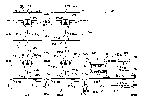
[00116] Referring to FIG. 1, a document processing system 100 is shown
according to
some embodiments of the present disclosure. According to some embodiments, the
document processing system 100 is a currency processing system. The document
processing
system 100 includes a document processing device 101, a first base module 102,
a second
CA 02786231 2012-06-29
WO 2011/109569 PCT/US2011/026935
14
base module 103, a first pocket module 104, and a second pocket module 105.
According to
some embodiments, the document processing device 101 is configured to process
a variety of
documents such as currency bills, checks, header/trailer cards, deposit slips,
cash-in tickets,
and cash-out tickets. While FIG. 1 illustrates a document processing system
100 having a
particular number and arrangement of devices and modules, it is contemplated
that a
document processing system according to the present disclosure can have a
variety of other
numbers of devices and modules with the same and/or different relative
positions. For
example, according to some embodiments, a document processing system can have
between
one and four base modules and between zero and twelve pocket modules. For
another
example, according to some embodiments, a document processing system can have
between
one and ten base modules and/or between zero and one hundred pocket modules.
Various
other numbers of base module and pocket module combinations are possible and
are
contemplated, such as, for example, those shown in FIGS. 2A-2D, 3A-3F, 7A-7G,
8A-8G,
9A-9G, 10A-10G, 11A-11G, and 12A-12H.
[00117] Referring to FIGS. 2A-2D, a document processing system 200 is
shown
according to some embodiments of the present disclosure. The document
processing system
200 is similar to the document processing system 100 in that the document
processing system
200 includes a document processing device 101, a first base module 102, and a
first pocket
module 104, which are the same as, or similar to, the document processing
device 101, the
first and/or the second base modules 102, 103, and the first and/or the second
pocket modules
104, 105 respectively. Throughout this disclosure, reference is made to the
document
processing systems 100 and 200 for illustrative purposes where like
components/elements
have like reference numbers. While system 100 includes modules (the second
base module
103 and the second pocket module 105) not included in the document processing
system 200,
it is understood that the document processing system 200 can include such
additional
modules and/or fewer modules.
DOCUMENT PROCESSING DEVICE
[00118] Referring generally to FIGS. 1 and 2A-2D, according to some
embodiments,
the document processing device 101 includes an input receptacle 110, a device
transport
mechanism 120, and a device outlet opening 130. While, only one input
receptacle 110 and
one device outlet opening 130 are shown, it is contemplated that according to
some
embodiments, the document processing device 101 may include a plurality of
input
receptacles 110 and/or a plurality of device outlet openings 130. Details of
such
CA 02786231 2014-07-09
systems/devices are described in International Publication No. WO 97/45810 and
U.S. Patent
No. 6,311,819, entitled "Method and Apparatus for Document Processing"
(Attorney Docket
No. 247171-000174).
[00119] Referring
to FIG. I, the input receptacle 110 is positioned proximate to a first
end 101a of the document processing device 101. According to some embodiments,
the
document processing device 101 is configured to receive only one document at a
time.
According to other embodiments, the document processing device 101 is
configured to
receive a stack of documents 135 in the input receptacle 110. According to
some
embodiments, the stack of documents 135 only includes U.S. currency bills. It
is
contemplated that in lieu of or in addition to bills, the stack of bills 135
can include one or
more of a variety of other types of documents, such as, for example, currency
bills of one or
more countries, financial documents such as, for example, checks, and/or
deposit documents
such as those described above in the Definitions Section. According to some
embodiments,
the stack of documents 135 can include one or more sorted batches of documents
and/or one
or more intermingled batches of documents, such as, for example, intermingled
bills and
checks.
[00120] According
to some embodiments, the stack of documents 135 includes a first
batch of documents and a second batch of documents. According to some such
embodiments, the first batch of documents solely includes bills and the second
batch of
documents solely includes checks. According to some embodiments, the first
batch of
documents is inputted and processed separately from the second batch of
documents.
According to some embodiments, the first batch of documents is received in a
first input
receptacle and the second batch of documents is received in a second separate
input
receptacle. In such embodiments, the first and the second batches of documents
can be run
and/or transported simultaneously or one after the other.
[00121] The device
transport mechanism 120 is coupled to the input receptacle 110
and is configured to transport the plurality of documents 135 along a first
segment 125a of a
transport path. The documents, such as bills 135a (shown in FIG. 1 at various
positions as
135a1_7), are transported via the device transport mechanism 120 in the
direction of art-ow A
from the first end 101a to a second opposing end 101b of the document
processing device
101, past at least one detector, and to the device outlet opening 130, which
is located in the
second end 101b of the document processing device 101.
[00122] According
to some embodiments, the at least one detector is configured to
detect characteristic information from the documents 135 and generate one or
more electrical
CA 02786231 2014-07-09
16
signals associated with the documents. According to some embodiments, the
document
processing device 101 includes a plurality of detector bays for mounting a
plurality of
detectors. In some embodiments, the document processing device 101 includes
two or more
detector bays. In some embodiments, the document processing device 101
includes three or
four detector bays along a first side of the first segment of the transport
path such as adjacent
to a top side of the transport path, and/or three or four corresponding
detector bays along a
second opposing side of the first segment of the transport path such as
adjacent to a bottom
side of the transport path. According to some embodiments, the plurality of
detector bays are
universal such that each one of the detector bays is configured to receive a
variety of different
types of detectors and/or sensors, such as, for example, image scanners,
authentication
sensors, and density sensors.
[00123] According to some embodiments, the at least one detector includes
one or
more denomination sensors, one or more image scanner(s) 140a and/or 140b, one
or more
authentication sensors or units 145, one or more density sensors, or a
combination thereof.
According to some embodiments, the document processing device 101 includes a
single
image scanner 140a to scan and/or image one or both sides of each passing
bill. According to
other embodiments, the document processing device 101 includes a first image
scanner 140a
to scan and/or image a first side of each passing document and a second
scanner 140b to scan
and/or image a second opposing side of each respective passing document. The
second
image scanner 140b is positioned on an opposing side of the first segment 125a
of the
transport path as compared with the position of the first image scanner 140a.
According to
some embodiments, the second image scanner 140b is opposite or off-set up or
downstream
from the first image scanner 140a.
[00124] According to some embodiments, the document processing device 101
does
not include any image scanners. According to some such embodiments, the
document
processing device 101 includes denomination sensors for denominating currency
bills.
Additional details on such non-imaging denominating devices are described in
U.S. Patent
No. 5,295,196, entitled "Method and Apparatus for CuiTency Discrimination and
Counting"
(Attorney Docket No. CUMM:072); U.S. Patent No. 5,815,592, entitled "Method
and
Apparatus for Discriminating and Counting Documents" (Attorney Docket No.
CUMM131);
and U.S. Patent No. 5,790,697, entitled "Method and Apparatus for
Discriminating and
Counting Documents" (Attorney Docket No. CUMM:125).
CA 02786231 2014-07-09
V
17
[00125]
According to some embodiments, the document processing device 101
includes an authentication sensor or authentication unit 145. Yet according to
other
embodiments, the document processing device 101 does not include an
authentication
sensor/unit 145. In some such embodiments, the lack of the authentication
sensor/unit 145
reduces the overall weight and cost of the document processing device 101. For
bills,
authentication can be accomplished using the authentication sensor/unit 145
and/or by using a
database of serial numbers for known or suspected counterfeit currency bills.
The
authentication sensor/unit 145 is optionally positioned adjacent to the first
segment 125a of
the transport path in a similar fashion as the image scanner(s) 140a and/or
140b. The
authentication sensor/unit 145 is configured to authenticate the documents 135
based on one
or more criteria and/or authentication tests as is commonly known in the art.
Some examples
of authentication sensors/units and authentication tests are described in U.S.
Patent No.
5,640,463, issued on June 17, 1997, entitled "Method and Apparatus For
Authenticating
Documents Including Currency" (Attorney Docket No. 247171-000115); U.S. Patent
No.
5,790,693, issued on August 4, 1998, entitled "Currency Discriminator and
Authenticator"
(Attorney Docket No. 247171-000141); U.S. Patent No. 5,992,601, issued on
November 30,
1999, entitled "Method and Apparatus for Document Identification and
Authentication"
(Attorney Docket No. 247171-000152); and U.S. Patent No. 5,960,103, issued on
September
28, 1999, entitled "Method and Apparatus for Authenticating Currency"
(Attorney Docket
No. 247171-000176).
[00126]
According to some embodiments, the input receptacle 110 is configured to
receive the stack of bills or documents 135 with a wide edge or a longer edge
of the
documents 135 being initially fed into the document processing device 101.
That is,
according to some embodiments, the wide edge of the stack of bills or
documents 135 is
perpendicular to the direction of an-ow A (FIGS. 1 and 2A), which is also
called the feed
direction. According to some embodiments, the documents are transported in a
wide edge
leading manner such that one of the wide edges of each document is the sole
leading edge
during the transport of that document from the input receptacle to an output
receptacle, such
as one of the output receptacles 190a-h, which are described in below.
[00127]
According to some embodiments, transporting the stack of bills/documents
135 with the wide edge leading can increase the overall processing speed of
the document
processing device 101. According to some embodiments, the transport
mechanism(s) (e.g.,
device transport mechanism 120) can transport the stack of documents 135 with
the wide
CA 02786231 2012-06-29
WO 2011/109569 PCT/US2011/026935
18
edge leading at a decreased linear speed while simultaneously increasing the
processing
speed of the document processing device 101. According to some embodiments,
transporting
the stack of documents 135 with the wide edge leading uses shorter transport
paths as
compared to systems that transport with the narrow edge leading. According to
some
embodiments, the shorter transport paths are employed to minimize and/or
reduce the size
and weight of the document processing system 100, 200.
[00128] According to some embodiments, the documents are transported in a
wide
edge leading manner such that each of the documents is moved from the input
receptacle 110
to one of the plurality of output receptacles 190a-h without rotating the
document around an
axis passing through a leading edge and a trailing edge of the document. That
is, according
to some embodiments, a document is not flipped about an axis passing through
its leading
edge and its trailing edge to change the face orientation of the document. It
is contemplated
that according to such embodiments, for documents transported in a wide edge
leading
manner as described above, the documents can be faced by rotating and/or
flipping the
documents about an axis passing through both of the narrower edges. Such a
facing can
occur as the documents are deposited into one of the output receptacles. For
example, as a
bill is transported in the wide edge leading manner in the direction of arrow
F (FIGS. 1 and
2B), the bill can be directed and deposited in the third output receptacle
190c such that a first
side of the bill is facing upwards or the bill can be directed and deposited
in the fourth output
receptacle 190d such that a second opposing side of the bill is facing
upwards. It is
contemplated that according to some embodiments, to face documents ¨ that is,
to deposit
documents in the output receptacles 190a-h such that all documents face in the
same
direction, e.g., upward ¨ the document processing systems 100, 200 can
determine the face
orientation of the documents and deposit the documents in an appropriate
output receptacle
such that the documents are all faced without rotating a single one of the
documents about an
axis passing through a leading edge and a trailing edge of the document.
[00129] According to some embodiments, the input receptacle 110 includes
two
slidable guides that are adjustable such that the input receptacle 110 can
receive the stack of
documents 135 with the wide edge leading or a narrow edge or shorter edge of
the documents
leading. That is, according to some alternative embodiments, the narrow edge
of the
documents 135 is perpendicular to the feed direction.
[00130] According to some embodiments, a controller or processor 150 is
coupled to
the image scanner(s) 140a and/or 140b, the device transport mechanism 120, a
memory 160,
an operator interface or control panel 170, and a communications port or
network device 180.
CA 02786231 2012-06-29
WO 2011/109569 PCT/US2011/026935
19
The controller 150 is configured to control the operation of the device
transport mechanism
120 and the image scanner(s) 140a and/or 140b. The controller 150 is also
configured to
communicate information to and from the memory 160, the control panel 170, and
the
communications port 180. For example, the controller 150 may send information
to and
receive operator input from the control panel 170. The control panel 170 can
be configured
to display information regarding the documents 135 and/or status information
concerning the
operation of the document processing system 100. For example, according to
some
embodiments, the control panel 170 is configured to display an image or a
partial image (e.g.,
snippet image) of a document of concern, such as, for example, a currency bill
that is
identified as a possible counterfeit currency bill, also known as a suspect
currency bill.
According to some embodiments, the controller 150 comprises one or more
computers. In
these embodiments, the controller 150 can include a plurality of memory
devices (e.g., RAM,
ROM, Hard Drive, etc.), processor(s), etc. necessary to perform a plurality of
document
processing actions within the document processing system 100. Some examples of
document
processing actions may include, but are not limited to, cropping and deskewing
images and/or
data, compressing data, down-sampling, denominating bills, extracting
information (e.g.,
character information, serial numbers, MICR lines, etc.), comparing extracted
data with one
or more databases, determining information from and/or analyzing data, storing
data,
transmitting data, etc.
[00131] According to some embodiments, in response to the image scanners
140a
and/or 140b scanning and/or imaging documents, the image scanners 140a and/or
140b
generate one or more electrical signals associated with the scanned and/or
imaged documents.
According to some embodiments, the one or more electrical signals are
transmitted to one or
more controllers and/or processors, such as, for example, the controller 150.
The controller
150 is configured to receive the one or more electrical signals and to derive
and/or generate
data therefrom. According to some embodiments, the one or more electrical
signals are
analog signals that the controller 150 is configured to convert into one or
more digital signals
using, for example, an analog-to-digital converter (ADC). The derived data can
include, for
example, image data, authentication data, positional data (e.g., position of
document along
the first segment), etc. According to some embodiments, the image data can be
reproduced
as one or more visually readable images of the documents.
[00132] According to some embodiments, the operator can initiate document
processing via use of the control panel 170. According to some embodiments,
the operator
can initiate document processing via use of a computer (not shown)
communicatively
CA 02786231 2012-06-29
WO 2011/109569 PCT/US2011/026935
connected to the document processing device 101 via, for example, the
communications port
180. According to some embodiments, the control panel 170 is a full graphics
color touch
screen display with various soft touch keys used to operate the document
processing system
100, 200 such as the control panel 170 shown in FIG. 2A. Alternatively or
additionally, the
control panel 170 may contain physical keys or buttons and/or another type of
display such as
an LED display. For example, a QWERTY keyboard and/or a ten key numerical
keypad may
be utilized. According to some embodiments, the control panel 170 displays
"functional"
keys when appropriate. According to some embodiments, the control panel 170 is
integrated
within a single housing of the document processing device 101. Alternatively,
the control
panel 170 can be remotely positioned from the document processing device 101,
but
communicatively connected therewith via, e.g., a wired connection and/or a
wireless
connection.
[00133] In response to the initiation of document processing, the device
transport
mechanism 120 transports the stack of documents 135 in the direction of arrow
A in a serial
fashion, one document at a time, one after another. As the documents 135 are
transported
along the first segment 125a of the transport path via the device transport
mechanism 120,
data associated with each document, such as, for example, bill 135a1, is
generated and/or
derived using the at least one detector, such as, for example, the image
scanner(s) 140a and/or
140b and/or the controller 150.
[00134] According to some embodiments, the generated and/or derived data
is image
data that is reproducible as a visually readable image or a human readable
image of
substantially the entire bill 135a1 (a "full image") and/or of selected
portions of the bill 135a1
(a "snippet image"). According to some embodiments, a visually readable and/or
human
readable image is defined based on a number of dots or pixels per inch ("DPI")
that form the
image. For purposes of the present disclosure, a visually readable image is an
image having a
resolution of at least 50 DPI x 50 DPI ¨ that is, the image includes 2500 dots
or pixels per
square inch. According to some embodiments, the visually readable image is
formed with a
resolution of at least 100 DPI x 100 DPI. According to some embodiments, the
visually
readable image is formed with a resolution of at least 200 DPI x 100 DPI.
According to some
embodiments, the visually readable image is formed with a resolution of at
least 200 DPI x
200 DPI. As the DPI increase, the amount of data generated by the image
scanner(s) 140a
and/or 140b increases, which may be a factor in causing relatively slower
processing speeds
in some embodiments. According to some embodiments, the resolution of an image
is
defined as P DPI X Q DPI, where P is the resolution in the x-direction or the
direction
CA 02786231 2014-07-09
21
perpendicular to the feed direction, and Q is the resolution in the y-
direction or the direction
parallel to the feed direction.
[00135] According
to some embodiments, the image scanner(s) 140a and/or 140b, the
controller 150, and/or the memory 160 includes data extraction software such
as optical
character recognition (OCR) software for identifying characters contained in
one or more
fields of the visually readable images of the documents 135 and extracting the
characters as
extracted data. It is contemplated that according to some embodiments, other
software can be
used to extract character or symbol information from the visually readable
images.
According to some embodiments, the document processing system 100 uses the OCR
software to obtain or extract identifying information from each of the
visually readable
images. For example, the OCR software may implement a search of the visually
readable
image of a currency bill for a serial number data field and extract a serial
number of the
currency bill once the data field is located. Additional details regarding OCR
can be found in
U.S. Provisional Patent Application No. 61/259,018, filed November 6, 2009,
also identified
as Attorney Docket No. 247171-000532PL07.
[00136] According
to some embodiments, the visually readable image is formed with a
resolution of 300 DPI x 200 DPI, 300 DPI x 300 DPI, 400 DPI x 200 DPI, or 400
DPI x 400
DPI. Such elevated resolutions can be desired when using OCR software to
extract relatively
small characters from an image. For example, when trying to extract small
characters on a
currency bill, such as, for example, back plate numbers found on U.S. currency
bills, the
image scanner(s) 140a and/or 140b can be configured to generate visually
readable images
having elevated resolutions (e.g., 400 DPI x 200 DPI). According to some
embodiments, if
fine printing defects are to be identified, a higher resolution, such as, for
example, 1200 DPI
x 1200 DPI or 2400 DPI x 2400 DPI, could be used.
[00137] According
to some embodiments, the memory 160 is configured to store
and/or buffer data associated with the documents 135. The data can be
reproducible as a
visually readable image when read and displayed on a display device (e.g.,
control panel 170)
or printed on a printing device (not shown). The visually readable image can
be a full
visually readable image that depicts the bill 135a1 or a partial or snippet
visually readable
image (e.g., serial number snippet image) that depicts the bill 135a1.
According to some
embodiments, the memory 160 is configured to store and/or buffer extracted
and/or inputted
data, such as, for example, identifying information and/or transactional
information
associated with the stack of documents 135. The identifying information can
include, for
CA 02786231 2014-07-09
22
example, serial numbers, denominations, batch/deposit identification numbers,
MICR
data/lines, etc. The transaction information can include, for example, a
financial institution
account number, a transaction identifier, a customer name, address, phone
number, a total
deposit amount, a total currency bill deposit amount, and/or a number of
deposited currency
bills broken down by denomination, a total check deposit amount, and/or a
number of
deposited checks.
[00138] According
to some embodiments, the memory 160 is configured to store a
database and/or a suspect database. According to some embodiments, a number of
types of
information can be used to assess whether a currency bill is a suspect
currency bill, including
serial number, denomination, series, check letter and quadrant number, check
letter and face
plate number, back plate number, federal reserve letter/number, signatories,
issuing bank,
image quality, infrared characteristics, magnetic characteristics, ultraviolet
characteristics,
color shifting ink, watermarks, metallic threads, holograms, etc., or some
combination
thereof. Additional details on databases and authentication using such
databases are
described in U.S. Patent Application No. 61/259,018, entitled "Apparatus for
Imaging
Currency Bills and Financial Documents and System and Method for Using the
Same"
(Attorney Docket No. 247171-000532PL07).
[00139] According
to some embodiments, the document processing device 101 is
configured to determine a fitness of each document being processed. For
example, the
document processing device 101 can employ one or more fitness sensors to
determine if a
currency bill is worn, torn, soiled, holes, marked, etc. According to some
such embodiments,
unfit documents can be sorted to one or more specified output receptacles for
further
processing by an operator of the document processing system 100. Additional
disclosure on
determining fitness of a document can be found in U.S. Patent No. 6,913,260,
entitled
"Currency Processing System with Fitness Detection" (Attorney Docket No.
247171-
368USPT) and U.S. Patent Application No. 2007/0122023 Al, entitled "Currency
Processing
System with Fitness Detection" (Attorney Docket No. 247171-440USPT).
[00140] As
described above, according to some embodiments, the controller 150 is
configured to communicate information to and from the communications port 180.
The
communications port 180 is configured to be communicatively connected to a
network (e.g.,
Internet, private network, customer network, financial institution network,
LAN, WAN,
secured network, etc.) to permit information to be transmitted to and from the
document
processing device 101. For example, according to some embodiments, the
document
CA 02786231 2012-06-29
WO 2011/109569 PCT/US2011/026935
23
processing device 101 comprises an Ethernet card comprising the communications
port 180
that is communicatively connected to a network. It is contemplated that
according to some
embodiments, the document processing device 101 includes two or more
communications
ports 180 to increase the flow and/or transfer of data to and from the
document processing
device 101.
[00141] Referring to FIG. 2A, the document processing device 101 is shown
with a
moveable upper portion 215 in an open position. Opening the moveable upper
portion 215
provides access to one or more detectors and a portion of the transport
mechanism 120 such
that an operator can remove jammed documents, clean scanheads, etc. According
to some
embodiments, the moveable upper portion 215 pivots open about 30 degrees.
According to
some embodiments, the moveable upper portion 215 pivots open about 45 degrees.
According to some embodiments, the moveable upper portion 215 pivots open
about 60
degrees. According to some embodiments, the moveable upper portion 215 pivots
open
about 90 degrees. According to some embodiments, the moveable upper portion
215 pivots
open about 120 degrees. According to some embodiments, the control panel 170
is mounted
on the moveable upper portion 215 such that the control panel 170 moves with
the moveable
upper portion 215. According to other embodiments, the control panel 170 is
mounted
remote from the moveable upper portion 215 on the housing of the document
processing
device 101 or elsewhere, such as remote from the document processing system
200.
FIRST BASE MODULE
[00142] Referring generally to FIGS. 1 and 2A-2C, according to some
embodiments,
the first base module 102 has a first end 102a and a second opposing end 102b;
and a top
102c and an opposing bottom 102d. The first base module 102 includes a first
base module
transport mechanism 121a, a first output receptacle 190a, a second output
receptacle 190b, a
first base module 2-way diverter 194a (FIG. 2B), and a first base module 3-way
diverter 195a
(FIGS. 1 and 2B).
[00143] According to some embodiments, the first base module 102 is
configured to be
detachably and operatively connected with the second end 101b of the document
processing
device 101. That is, the first end 102a of the first base module 102 abuts the
second end 101b
of the document processing device 101 such that a first base module inlet
opening 115a
(FIGS. 1 and 2B) located in the first end 102a of the first base module 102
aligns with the
device outlet opening 130 (FIG. 1). According to some embodiments, the first
base module
inlet opening 115a is communicatively coupled with the device outlet opening
130 such that
CA 02786231 2012-06-29
WO 2011/109569 PCT/US2011/026935
24
documents (e.g., bill 135a1) can be transported by the device transport
mechanism 120,
through the device outlet opening 130, through the first base module inlet
opening 115a, and
further transported by the first base module transport mechanism 121a.
According to some
embodiments, mechanically coupling and/or abutting the first base module 102
with the
document processing device 101 also communicatively and/or electronically
couples the first
base module 102 with the document processing device 101 such that one or more
components
of the document processing device 101 (e.g., the controller 150) is
communicatively
connected with one or more components (e.g., the first base module 3-way
diverter 195a) of
the first base module 102.
[00144] According to some embodiments, the first and the second output
receptacles
190a,b (FIGS. 1, 2A-2C) are configured to receive documents, such as, the bill
135a1. The
first and the second output receptacles 190a,b are positioned between the
first end 102a and
the second end 102b and between the top 102c and the bottom 102d of the first
base module
102. According to some embodiments, the first and the second output
receptacles 190a,b are
horizontally offset from one another.
[00145] According to some embodiments, each of the first and the second
output
receptacles 190a,b includes a stacker plate 190a1,190b1 configured to allow
processed bills to
rest thereon. According to some embodiments, the output receptacles 190a,b
further include
entry rollers (e.g., including drive roller 192b, belt 192c, and wheels 192d,e
described below
and shown in FIG. 2D). The entry rollers bridge the gap between the transport
mechanism
and the output receptacle by receiving bills from the transport mechanism and
delivering the
bills into the output receptacle. According to some embodiments, the output
receptacle
optionally includes a stacker wheel (e.g., stacker wheels 197a,b shown in
FIGS. 2B-2D)
positioned between the stacker plate 190a1, 190b1 and the entry rollers. The
stacker wheel
can be configured to receive bills from the entry rollers and to deliver bills
to the stacker
plate. While the first and the second output receptacles 190a,b are shown as
including
stacker plates, entry rollers, and stacker wheels, it is contemplated that
first and the second
output receptacles 190a,b may include only one or two of these components. For
example, it
is contemplated that first and the second output receptacles 190a,b can only
include a stacker
plate without a stacker wheel and without entry rollers. Alternatively or
additionally other
mechanisms and arrangements for receiving documents in output receptacles
known in the art
may be employed according to some embodiments.
[00146] The first base module transport mechanism 121a (FIGS. 1 and 2A) is
configured to transport documents along a second segment 125b (FIGS. 1 and 2B)
of the
CA 02786231 2012-06-29
WO 2011/109569 PCT/US2011/026935
transport path in the direction of arrow B. The second segment 125b extends
generally from
the first base module inlet opening 115a to a first outlet opening 131a (FIG.
1) located in the
second end 102b of the first base module 102. According to some embodiments,
the second
segment 125b is positioned at least partially beneath the first and the second
output
receptacles 190a,b. The first base module transport mechanism 121a is further
configured to
selectively transport documents along a third segment 125c (FIGS. 1 and 2B) of
the transport
path. The third segment 125c extends generally-vertically upward from the
second segment
125b of the transport path in the direction of arrow C and between the first
and the second
output receptacles 190a,b. According to some embodiments, a controller (e.g.,
the controller
150) controls whether the first base module transport mechanism 121a delivers
a document
along the second segment 125b beneath the third segment 125c and toward the
first outlet
opening 131a of the first base module 102 or transports the document generally
upward in the
direction of arrow C along the third segment 125c. According to some such
embodiments,
the controller is configured to control the first base module 2-way diverter
194a (FIGS. 2B-
2C) positioned at the junction of the second segment 125b and the third
segment 125c to
selectively direct documents along the second segment 125b or the third
segment 125c of the
transport path.
[00147] According to some embodiments, the first base module 3-way
diverter 195a
(FIGS. 1 and 2B-2D) is positioned along the third segment 125c of the
transport path and
between the first and the second output receptacles 190a,b. According to some
embodiments,
the first base module 3-way diverter 195a is configured to transition between
at least three
distinct positions to selectively direct documents along one of at least three
distinct paths or
directions. According to some such embodiments, the first base module 3-way
diverter 195a
is configured to rotate and/or pivot about an axis between the at least three
distinct positions.
According to some embodiments, the first base module 3-way diverter 195a is a
single
unitary piece made of, for example, extruded plastic, molded plastic, and/or
metal.
According to some embodiments, the first base module 3-way diverter 195a
includes a slot
configured to pass documents therethrough. For example, the slot can be large
enough such
that a U.S. currency bill can be transported through the slot in a wide-edge
leading manner.
[00148] According to some embodiments, the first base module 3-way
diverter 195a
includes two 2-way diverters, where each of the 2-way diverters are a single
unitary piece
made of, for example, extruded plastic, molded plastic, and/or metal.
According to such
embodiments, the two 2-way diverters are configured to be controlled and/or to
move in
unison and/or in a cooperative fashion to selectively direct documents being
transported. For
CA 02786231 2012-06-29
WO 2011/109569 PCT/US2011/026935
26
example, the two 2-way diverters can be configured to be controlled by a
controller to
selectively direct documents into one of the first and the second output
receptacles 190a,b
and/or past both of the first and the second output receptacles 190a,b such as
to a second
outlet opening 13 lb. It is contemplated that the 3-way diverters of the
present disclosure can
be a single unitary 3-way diverter or a 3-way diverter comprised of two
cooperative 2-way
diverters as described above. According to some embodiments, the diverters are
not made of
a single unitary member but are constructed of several pieces.
[00149] Referring to FIG. 2D, according to some embodiments, a controller
is
configured to cause the first base module 3-way diverter 195a to reside in
and/or rotate to a
position to selectively direct documents being transported via the first base
module transport
mechanism 121a along the third segment 125c of the transport path. According
to some such
embodiments, the controller is configured to cause the first base module 3-way
diverter 195a
to reside in a first position to selectively direct documents from the third
segment 125c in the
direction of arrow D into the first output receptacle 190a. According to some
such
embodiments, the controller is configured to cause the first base module 3-way
diverter 195a
to reside in a second position to selectively direct documents from the third
segment 125c in
the direction of arrow E into the second output receptacle 190b. According to
some such
embodiments, the controller is configured to cause the first base module 3-way
diverter 195a
to reside in a third position to selectively direct documents in the direction
of arrow C past
both the first and the second output receptacles 190a,b toward the second
outlet opening 131b
located in the top 102c of the first base module 102. According to some
embodiments, in
response to the first base module 3-way diverter 195a residing in the third
position,
documents are transported in the direction of arrow C through the slot of the
first base
module 3-way diverter 195a. Thus, the first base module transport mechanism
121a can
transport documents from the first base module inlet opening 115a to one of
four locations
including, but not limited to, the first outlet opening 131a, the first output
receptacle 190a, the
second output receptacle 190b, and the second outlet opening 131b.
[00150] With reference to FIG. 2D, according to some embodiments, as the
documents
are selectively directed to one of the first or the second output receptacles
190a,b, the
documents are transported along a respective transition surface 192a, 193a.
For example, for
a document being transported from the third segment 125c of the transport path
to the first
output receptacle 190a via the first base module transport mechanism 121a, the
document is
transported from the third segment 125c in the direction of arrow D where the
document is
engaged between drive roller 192b and belt 192c. According to some
embodiments, the belt
CA 02786231 2012-06-29
WO 2011/109569 PCT/US2011/026935
27
192c is a passive belt around non-driven rollers or wheels 192d,e. The driver
roller 192b
moves the document further along the transport path and into engagement with
stacker
wheels 197a (also shown in FIGS. 2B and 2C) which rotate to deposit the
document in the
first output receptacle 190a.
[00151] According to some embodiments, the belt 192c is not employed and a
transport plate is positioned between rollers or wheels 192d,e. In such
embodiments, the
transport plate operates to guide documents from being positioned between
roller 193e and
roller 192b to being positioned between roller 193d and roller 192b. Rollers
192d,e are
positioned to engage and be driven by roller 192b.
[00152] For another example, for a document being transported from the
third segment
125c of the transport path to the second output receptacle 190b via the first
base module
transport mechanism 121a, the document is transported from the third segment
125c in the
direction of arrow E where the document is engaged between drive roller 193b
and belt 193c.
According to some embodiments, the belt 193c is a passive belt around non-
driven rollers or
wheels 193d,e. The driver roller 193b moves the document further along the
transport path
and into engagement with stacker wheels 197b (also shown in FIGS. 2B and 2C)
which rotate
to deposit the document in the second output receptacle 190b.
[00153] According to some embodiments, as a document is transported along
the
transition surface 192a,193a from the third segment 125c of the transport path
and into the
first or the second output receptacle 190a,b, the document is rotated by at
least about 90
degrees and/or the forward direction of the document is changed by at least
about 90 degrees.
According to some embodiments, as a document is transported along the
transition surface
192a,193a from the third segment 125c of the transport path and into the first
or the second
output receptacle 190a,b, the document is rotated between about 100 degrees
and about 140
degrees.
[00154] Referring generally to FIGS. 2A-2C, according to some embodiments,
the first
and the second output receptacles 190a,b each define a respective receiving
opening or
passage and a respective access opening. The receiving openings or passages
provide
document access into the first and the second output receptacles 190a,b in
response to the
first base module 3-way diverter 195a diverting documents therein from the
third segment
125c of the transport path. The receiving opening of the first output
receptacle 190a is
positioned adjacent to a first side of the third segment 125c of the transport
path and the
receiving opening of the second output receptacle 190b is positioned adjacent
to a second
opposing side of the third segment 125c of the transport path. That is, the
first and the second
CA 02786231 2012-06-29
WO 2011/109569 PCT/US2011/026935
28
output receptacles 190a,b are positioned within the first base module 102 such
that the
receiving opening of the first output receptacle 190a faces the receiving
opening of the
second output receptacle 190b. Such an output receptacle configuration is
called back-to-
back output receptacles. That is, two adjacent output receptacles on opposite
sides of a
transport segment of a transport path that each receive documents from a
common transport
mechanism are oriented in a back-to-back manner with respect to each other.
[00155] The access openings provide operator access from a front side of
the first base
module 102 to permit an operator to remove documents transported to and
deposited within
one of the first and the second output receptacles 190a,b. The access openings
can be
provided in any of a variety of shapes with any of a variety of dimensions
such that an
operator can remove deposited documents from the front side of the first base
module 102.
According to some embodiments, the access openings are selectively closed (not
shown).
For example, a door (not shown) can be provided to restrict physical access to
documents
deposited within the first or the second output receptacles 190a,b. The door
can be large
enough to restrict access into both of the first and the second output
receptacles 190a,b.
Alternatively, individual doors can be provided for restricting access into
each of the output
receptacles 190a,b.
[00156] According to some embodiments, each of the receiving openings lays
in one
or more parallel receiving planes and each of the access openings lays in one
or more parallel
access planes that are orthogonal or generally orthogonal to the one or more
receiving planes.
[00157] Referring to FIGS. 2A-2B, according to some embodiments, the first
base
module 102 includes an output receptacle 191a. According to some embodiments,
the output
receptacle 191a is the same as, or similar to, the output receptacles 190a-h.
According to
some embodiments, the output receptacle 191a is an offsort pocket or a reject
pocket.
According to some embodiments, the output receptacle 191a facilitates off-
sorting of larger
documents, such as, for example, commercial checks and 8.5" x 11" sheets.
While the first
base module 102 is illustrated as including the output receptacle 191a,
according to some
embodiments, the first base module 102 does not include the output receptacle
191a.
[00158] Referring back to FIG. 2A, according to some embodiments, the
first base
module transport mechanism 121a includes a lower moveable transport plate 127
and an
upper stationary transport plate 126. According to some embodiments, the
moveable
transport plate 127 has an open position (shown in FIG. 2A) and a closed
position (shown in
FIGS. 2B and 2C). According to some such embodiments, the moveable transport
plate 127
is pivotably coupled within the first base module 102 such that the moveable
transport plate
CA 02786231 2012-06-29
WO 2011/109569 PCT/US2011/026935
29
127 can pivot between the open and closed positions. In response to the
moveable transport
plate being in the closed position, the moveable transport plate 127 is
generally parallel to the
stationary transport plate 126. According to some embodiments, in response to
the moveable
transport plate 127 being in the open position, documents, such as currency
bills, remaining
on the moveable transport plate 127 slide toward a front side of the first
base module 102.
For example, during the processing of documents, currency bills are being
transported
between the stationary and the moveable transport plates 126,127. In the case
of a jam, an
operator can open and/or move the moveable transport plate 127 into the open
position,
whereby the bills are free to fall or slide toward the front of the module 102
due to gravity.
That is, document jams can be cleared using gravity to cause the jammed
documents to fall
out of the system 100, 200.
[00159] According to some embodiments, the first base module 102 includes
a latch
assembly including a latch 128a and a knob 128b. According to such
embodiments, the latch
assembly is configured to selectively retain the moveable transport plate 127
in its closed
position. According to some embodiments, the knob 128b is rigidly mounted to
the
moveable transport plate 127 and the latch 128a is pivotably mounted to the
stationary
transport plate 126. According to some embodiments, the latch 128a can include
a roller or
an angled engagement surface at one end thereof. According to some
embodiments, the knob
128b is configured to receive and mate with the roller or the angled
engagement surface and
thereby lock the latch 128a to the knob 128b such that the moveable transport
plate 127 is
retained in the closed position. According to some embodiments, the latch
assembly further
includes a biasing member configured to bias the latch 128a into the latched
orientation.
[00160] According to some embodiments, a width W of the first base module
102 is
between about twelve inches (30 cm) and about eighteen inches (46 cm).
According to some
embodiments, the width W of the first base module 102 is about sixteen inches
(41 cm).
According to some embodiments, a height H of the first base module 102 is
between about
eighteen inches (46 cm) and about twenty-two inches (56 cm). According to some
embodiments, the height H of the first base module 102 is about twenty inches
(51 cm).
According to some embodiments, a depth D of the first base module 102 is
between about
fifteen inches (38 cm) and about nineteen inches (49 cm). According to some
embodiments,
the depth D of the first base module 102 is about seventeen inches (43 cm).
[00161] According to some embodiments, the first base module 102 has a
footprint of
less than about two and a half square feet. According to some embodiments, the
first base
CA 02786231 2012-06-29
WO 2011/109569 PCT/US2011/026935
module 102 has a footprint of less than about two square feet. According to
some
embodiments, the first base module 102 has a footprint of less than one and a
half square feet.
[00162] According to some embodiments, the first base module 102 occupies
less than
about four and a half cubic feet. According to some embodiments, the first
base module 102
occupies less than about three and a half cubic feet. According to some
embodiments, the
first base module 102 occupies less than about three cubic feet. According to
some
embodiments, the first base module 102 occupies less than about two and a half
cubic feet.
FIRST POCKET MODULE
[00163] According to some embodiments, the first pocket module 104 has a
first end
104a and a second opposing end 104b; and a top 104c and an opposing bottom
104d. The
first pocket module 104 includes a first pocket module transport mechanism
122a, a third
output receptacle 190c, a fourth output receptacle 190d, and a first pocket
module 3-way
diverter 196a.
[00164] According to some embodiments, the first pocket module 104 is
configured to
be detachably and operatively connected with the top 102c of the first base
module 102. That
is, the bottom 104d of the first pocket module 104 abuts the top 102c of the
first base module
102 such that a first pocket module inlet opening 116a located in the bottom
104d of the first
pocket module 104 aligns with the second outlet opening 131b of the first base
module 102.
According to some embodiments, the first pocket module inlet opening 116a is
communicatively coupled with the second outlet opening 131b of the first base
module 102
such that documents (e.g., bill 135a3) can be transported by the first base
module transport
mechanism 121a, through the second outlet opening 131b of the first base
module 102,
through the first pocket module inlet opening 116a, and further transported by
the first pocket
module transport mechanism 122a. According to some embodiments, mechanically
coupling
and/or abutting the first pocket module 104 with the first base module 102
also
communicatively and/or electronically couples the first pocket module 104 with
the first base
module 102 and/or the document processing device 101 such that one or more
components of
the document processing device 101 (e.g., the controller 150) is
communicatively connected
with one or more components (e.g., the first pocket module 3-way diverter
196a) of the first
pocket module 104.
[00165] According to some embodiments, the third and the fourth output
receptacles
190c,d are configured to receive documents, such as, the bill 135a6. The third
and the fourth
output receptacles 190c,d are positioned between the first end 104a and the
second end 104b
CA 02786231 2012-06-29
WO 2011/109569 PCT/US2011/026935
31
and between the top 104c and the bottom 104d of the first pocket module 104.
According to
some embodiments, the third and the fourth output receptacles 190c,d are
horizontally offset
from one another.
[00166] The first pocket module transport mechanism 122a is configured to
transport
documents along a fourth segment 125d of the transport path in the direction
of arrow F. The
fourth segment 125d extends generally from the first pocket module inlet
opening 116a to a
first pocket module outlet opening 132a located in the top 104c of the first
pocket module
104. According to some embodiments, the fourth segment 125d extends generally
vertically
upward from the first pocket module inlet opening 116a and is positioned at
least partially
between the third and the fourth output receptacles 190c,d.
[00167] According to some embodiments, the first pocket module 3-way
diverter 196a
is positioned along the fourth segment 125d of the transport path and between
the third and
the fourth output receptacles 190c,d. According to some embodiments, the first
pocket
module 3-way diverter 196a is configured to transition between at least three
distinct
positions to selectively direct documents along one of at least three distinct
paths or
directions. According to some such embodiments, the first pocket module 3-way
diverter
196a is configured to rotate and/or pivot about an axis between the at least
three distinct
positions.
[00168] According to some embodiments, a controller is configured to cause
the first
pocket module 3-way diverter 196a to reside in and/or rotate to a position to
selectively direct
documents being transported via the first pocket module transport mechanism
122a along the
fourth segment 125d of the transport path. According to some such embodiments,
the
controller is configured to cause the first pocket module 3-way diverter 196a
to reside in a
first position to selectively direct documents from the fourth segment 125d in
the direction of
arrow G into the third output receptacle 190c. According to some such
embodiments, the
controller is configured to cause the first pocket module 3-way diverter 196a
to reside in a
second position to selectively direct documents from the fourth segment 125d
in the direction
of arrow H into the fourth output receptacle 190d. According to some such
embodiments, the
controller is configured to cause the first pocket module 3-way diverter 196a
to reside in a
third position to selectively direct documents in the direction of arrow F
past both the third
and the fourth output receptacles 190c,d toward the first pocket module outlet
opening 132a
located in the top 104c of the first pocket module 104. Thus, the first pocket
module
transport mechanism 122a can transport documents from the first pocket module
inlet
opening 116a to one of three locations including, but not limited to, the
third output
CA 02786231 2012-06-29
WO 2011/109569 PCT/US2011/026935
32
receptacle 190c, the fourth output receptacle 190d, and the first pocket
module outlet opening
132a.
[00169] According to some embodiments, the third and the fourth output
receptacles
190c,d each define a respective receiving opening and a respective access
opening. The
receiving openings provide document access into the third and the fourth
output receptacles
190c,d in response to the first pocket module 3-way diverter 196a diverting
documents
therein from the fourth segment 125d of the transport path. The receiving
opening of the
third output receptacle 190c is positioned adjacent to a first side of the
fourth segment 125d
of the transport path and the receiving opening of the fourth output
receptacle 190d is
positioned adjacent to a second opposing side of the fourth segment 125d of
the transport
path. That is, the third and the fourth output receptacles 190c,d are
positioned within the first
pocket module 104 such that the receiving opening of the third output
receptacle 190c faces
the receiving opening of the fourth output receptacle 190d in a back-to-back
manner as
defined above. The access openings of the first pocket module 104 are the same
as, or
similar to, the access openings of the first base module 102 discussed above.
[00170] According to some embodiments, a width W of the first pocket
module 104 is
between about twelve inches (30 cm) and about eighteen inches (46 cm).
According to some
embodiments, the width W of the first pocket module 104 is about sixteen
inches (41 cm).
According to some embodiments, a height H of the first pocket module 104 is
between about
four inches (10 cm) and about seven inches (18 cm). According to some
embodiments, the
height H of the first pocket module 104 is about five and a half inches (14
cm). According to
some embodiments, a depth D of the first pocket module 104 is between about
fifteen inches
(38 cm) and about nineteen inches (49 cm). According to some embodiments, the
depth D of
the first pocket module 104 is about seventeen inches (43 cm).
[00171] According to some embodiments, the first pocket module 104 has a
footprint
of less than about two and a half square feet. According to some embodiments,
the first
pocket module 104 has a footprint of less than about two square feet.
According to some
embodiments, the first pocket module 104 has a footprint of less than one and
a half square
feet.
[00172] According to some embodiments, the first pocket module 104
occupies less
than about one and a half cubic feet. According to some embodiments, the first
pocket
module 104 occupies less than about one cubic foot. According to some
embodiments, the
first pocket module 104 occupies less than about 0.9 cubic feet. According to
some
embodiments, the first pocket module 104 occupies less than about 0.8 cubic
feet.
CA 02786231 2012-06-29
WO 2011/109569 PCT/US2011/026935
33
SECOND BASE MODULE
[00173] According to some embodiments, the second base module 103 has a
first end
103a and a second opposing end 103b; and a top 103c and an opposing bottom
103d. The
second base module 103 is configured to be detachably and operatively
connected with the
second end 102b of the first base module 102 in the same, or similar manner,
as the first end
102a of the first base module 102 is configured to be detachably and
operatively connected
with the second end 101b of the document processing device 101. That is, the
first end 103a
of the second base module 103 abuts the second end 102b of the first base
module 102 such
that a second base module inlet opening 115b located in the first end 103a of
the second base
module 103 aligns with the first outlet opening 131a of the first base module
102. According
to some embodiments, the second base module inlet opening 115b couples with
the first
outlet opening 131a of the first base module 102 such that documents (e.g.,
bill 135a2) can be
transported by the first base module transport mechanism 121a, through the
first outlet
opening 131a of the first base module 102, through the second base module
inlet opening
115b, and further transported by the second base module transport mechanism
121b.
According to some embodiments, mechanically coupling and/or abutting the
second base
module 103 with the first base module 102 also communicatively and/or
electronically
couples the second base module 103 with the first base module 102 and/or the
document
processing device 101 such that one or more components of the document
processing device
101 (e.g., the controller 150) is communicatively connected with one or more
components
(e.g., a second base module 3-way diverter 195b) of the second base module
103.
[00174] According to some embodiments, the second base module 103 includes
an
output receptacle 19 lb. According to some embodiments, the output receptacle
19 lb is the
same as, or similar to, the output receptacles 190a-h. According to some
embodiments, the
output receptacle 191b is an offsort pocket or a reject pocket.
[00175] According to some embodiments, the first and the second base
modules 102,
103 are structurally identical and operatively interchangeable. In some such
embodiments,
the second base module 103 can be detachably and operatively connected with
the second
end 101b of the document processing device 101 in the same, or similar, manner
as the first
end 102a of the first base module 102 is configured to be detachably and
operatively
connected with the second end 101b of the document processing device 101.
[00176] According to some embodiments, the second base module 103 is the
same as,
or similar to, the first base module 102, where like reference numbers are
used to indicate like
CA 02786231 2012-06-29
WO 2011/109569 PCT/US2011/026935
34
components. For example, the second base module 103 includes the second base
module
inlet opening 115b, a first outlet opening 131c of the second base module 103,
a second outlet
opening 131d of the second base module 103, a second base module transport
mechanism
121b including a fifth segment 125e and a sixth segment 125f of the transport
path, a fifth
output receptacle 190e, a sixth output receptacle 190f, a second base module 2-
way diverter
194b, and the second base module 3-way diverter 195b, which are the same as,
or similar to,
the first base module inlet opening 115a, the first outlet opening 131a of the
first base module
102, the second outlet opening 131b of the first base module 102, the first
base module
transport mechanism 121a including a second segment 125b and a third segment
125c of the
transport path, the first output receptacle 190a, the second output receptacle
190b, the first
base module 2-way diverter 194a, and the first base module 3-way diverter
195a,
respectively. According to some embodiments, the second base module transport
mechanism
121b of the second base module 103 includes an upper stationary transport
plate (not shown)
and a lower moveable transport plate (not shown), which are the same as, or
similar to, the
stationary transport plate 126 and the moveable transport plate 127 described
above in
reference to the first base module 102.
[00177] According to some embodiments, the first outlet opening 131c of
the second
base module 103 is configured to be mechanically coupled with and/or abutting
a strapper
module (not shown), a facing module (not shown), an inlet opening of another
base module
(e.g., inlet opening 115a), or another ancillary device and/or module.
According to some
embodiments, mechanically coupling and/or abutting the second base module 103
with an
ancillary device or module also communicatively and/or electronically couples
the second
base module 103 with the ancillary device or module such that one or more
components of
the document processing device 101 (e.g., the controller 150) is
communicatively connected
with one or more components (e.g., a strapping unit) of the ancillary device
or module.
SECOND POCKET MODULE
[00178] According to some embodiments, the second pocket module 105 has a
first
end 105a and a second opposing end 105b; and a top 105c and an opposing bottom
105d.
The second pocket module 105 is configured to be detachably and operatively
connected with
the top 103c of the second base module 103 in the same, or similar manner, as
the bottom
104d of the first pocket module 104 is configured to be detachably and
operatively connected
with the top 102c of the first base module 102. That is, the bottom 105d of
the second pocket
module 105 abuts the top 103c of the second base module 103 such that a second
pocket
CA 02786231 2012-06-29
WO 2011/109569 PCT/US2011/026935
module inlet opening 116b located in the bottom 105d of the second pocket
module 105
aligns with the second outlet opening 131d of the second base module 103.
According to
some embodiments, the second pocket module inlet opening 116b couples with the
second
outlet opening 131d of the second base module 103 such that documents (e.g.,
bill 135a5) can
be transported by the second base module transport mechanism 121b, through the
second
outlet opening 131d of the second base module 103, through the second pocket
module inlet
opening 116b, and further transported by the second pocket module transport
mechanism
122b. According to some embodiments, mechanically coupling and/or abutting the
second
pocket module 105 with the second base module 103 also communicatively and/or
electronically couples the second pocket module 105 with the second base
module 103, the
first base module 102, the first pocket module 104, and/or the document
processing device
101 such that one or more components of the document processing device 101
(e.g., the
controller 150) is communicatively connected with one or more components
(e.g., the second
pocket module 3-way diverter 196b) of the second pocket module 105.
[00179] According to some embodiments, the first and the second pocket
modules 104,
105 are structurally identical and operatively interchangeable. In some such
embodiments,
the second pocket module 105 can be detachably and operatively connected with
the top 102c
of the first base module 102 in the same, or similar manner, as the bottom
104d of the first
pocket module 104 is configured to be detachably and operatively connected
with the top
102c of the first base module 102.
[00180] According to some embodiments, the second pocket module 105 is the
same
as, or similar to, the first pocket module 104, where like reference numbers
are used to
indicate like components. For example, the second pocket module 105 includes a
second
pocket module inlet opening 116b, a second pocket module outlet opening 132b,
a second
pocket module transport mechanism 122b including a seventh segment 125g of the
transport
path, a seventh output receptacle 190g, an eighth output receptacle 190h, and
a second pocket
module 3-way diverter 196b, which are the same as, or similar to, first pocket
module inlet
opening 116a, the first pocket module outlet opening 132a, the first pocket
module transport
mechanism 122a including the fourth segment 125d of the transport path, the
third output
receptacle 190c, the fourth output receptacle 190d, and the first pocket
module 3-way diverter
196a, respectively.
INTERCHANGEABLE AND STACKABLE MODULES
CA 02786231 2012-06-29
WO 2011/109569 PCT/US2011/026935
36
[00181] According to some embodiments, the first pocket module 104 can be
detachably connected to the top 103c of the second base module 103 and receive
documents
transported through the second outlet opening 131d of the second base module
103.
Similarly, the second pocket module 105 can be detachably connected to the top
102c of the
first base module 102 and receive documents transported through the second
outlet opening
131b of the first base module 102.
[00182] According to some embodiments, the first pocket module 104 can be
detachably connected to the top 105c of the second pocket module 105 to
receive documents
therethrough. That is, the first pocket module 104 can be detachably connected
to the second
pocket module 105 such that the first pocket module inlet opening 116a mates
with the
second pocket module outlet opening 132b to receive documents therefrom.
Similarly, the
second pocket module 105 can be detachably connected to the top 104c of the
first pocket
module 104 to receive documents transported therethrough. That is, the second
pocket
module 105 can be detachably connected to the first pocket module 104 such
that the second
pocket module inlet opening 116b mates with the first pocket module outlet
opening 132a to
receive documents therefrom.
DOCUMENT TRANSPORT PATH EXAMPLES
[00183] According to some embodiments, a stack of bills 135 is received in
the input
receptacle 110 of the document processing device 101. As described above, the
device
transport mechanism 120 transports the bills one at a time along the transport
path. The
following description focuses on some of the various transport paths of one of
the bills 135a.
As shown in FIG. 1, the bill 135a1 is first shown in the first segment 125a of
the transport
path being transported in the direction of arrow A past the image scanner(s)
140a and/or
140b. According to some embodiments, as the bill 135a1 is transported in the
direction of
arrow A along the first segment 125a of the transport path, the document
processing system
100 determines a desired final destination or location for the bill 135a based
at least in part on
data generated by the image scanner(s) 140a and/or 140b and/or the
authentication unit 145
and/or other sensor(s).
[00184] For example, the document processing system 100 shown in FIG. 1
includes
eight output receptacles 190a-h. The document processing system 100, thus, can
determine
to transport and deliver the bill 135a into any one of the eight output
receptacles 190a-h based
on a bill's denomination, authenticity, fitness, face orientation, etc.
According to some
embodiments, each one of the output receptacles 190a-h is assigned a
denomination of a
CA 02786231 2012-06-29
WO 2011/109569 PCT/US2011/026935
37
currency bill. For a standard set of U.S. currency bills having seven
different denominations
(e.g., $1, $2, $5, $10, $20, $50, $100), one of the eight output receptacles
remains to serve as
a reject receptacle, or as a duplicate receptacle.
[00185] According to some embodiments, the first output receptacle 190a is
assigned
to receive $1' s, the second output receptacle 190b is assigned to receive
$2's, the third output
receptacle 190c is assigned to receive $5' s, the fourth output receptacle
190d is assigned to
receive $10's, the fifth output receptacle 190e is assigned to receive $20's,
the sixth output
receptacle 190f is assigned to receive $50's, the seventh output receptacle
190g is assigned to
receive $100's, and the eighth output receptacle 190h can be assigned to
receive suspect bills.
It is contemplated that various other assignments of output receptacles 190a-h
are possible.
According to some embodiments, an operator of the document processing system
100 can
assign a particular denomination and/or document type (e.g., check, deposit
slip,
header/trailer card, etc.) to a particular output receptacle via the control
panel 170.
According to some embodiments, each output receptacle 190a-h is automatically
assigned a
denomination and/or document type. It is contemplated that according to some
embodiments,
assignment of the output receptacles 190a-h can be manual, automatic, or a
combination
thereof.
[00186] Proceeding with the above example and assuming that the bill 135a
is a $100,
the device transport mechanism 120 transports the bill 135a1 in the direction
of arrow A
along the first segment 125a of the transport path through the device outlet
opening 130. The
document processing device 101 determines that the bill 135a1 is a non-suspect
$100 bill and
thus should be transported and delivered to the seventh output receptacle
190g. In response
to the determination of the bill 135a1, the bill 135a2 is received through the
first base module
inlet opening 115a and engaged with the first base module transport mechanism
121a. The
bill 135a2 is transported beneath the first and the second output receptacles
190a,b in the
direction of arrow B, under or past the first base module 2-way diverter 194a,
and to the first
outlet opening 131a of the first base module 103. The bill 135a4 is received
through the
second base module inlet opening 115b and engaged with the second base module
transport
mechanism 121b. The bill 135a4 is transported beneath the fifth output
receptacle 190e in the
direction of arrow I and then transitioned and/or diverted from the fifth
segment 125e of the
transport path in a generally vertical manner in the direction of arrow J onto
the sixth segment
125f of the transport path via the second base module 2-way diverter 194b. The
bill 135a5 is
transported between the fifth and the sixth output receptacles 190e,f and past
or through the
second base module diverter 195b towards the second outlet opening 131d of the
second base
CA 02786231 2012-06-29
WO 2011/109569 PCT/US2011/026935
38
module 103. The bill 135a7 is received through the second pocket module inlet
opening 116b
and engaged with the second pocket module transport mechanism 122b. The bill
135a7 is
transported in a generally vertical manner in the direction of arrow M toward
the second
pocket module 3-way diverter 196b. According to some embodiments, the
controller 150
instructs and/or causes the second pocket module 3-way diverter 196b to adjust
its position
such that the bill 135a7 is directed in the direction of arrow N into the
seventh output
receptacle 190g as the second pocket module transport mechanism 122b
transports the bill
135a7 along the seventh segment 125g of the transport path.
[00187] According to some embodiments of the example disclosed above,
assuming
the bill 135a was determined to be a suspect bill rather than a non-suspect,
the document
processing system 100 determines to transport and deliver the bill 135a to the
eight output
receptacle 190h, which was designated as the reject receptacle. Thus, instead
of the
controller 150 instructing and/or causing the second pocket module 3-way
diverter 196b to
adjust its position such that the bill 135a7 is directed in the direction of
arrow N, the
controller instructs and/or causes the second pocket module 3-way diverter
196b to adjust its
position such that the bill 135a7 is directed in the direction of arrow 0 into
the eight output
receptacle 190h as the second pocket module transport mechanism 122b
transports the bill
135a7 along the seventh segment 125g of the transport path.
[00188] In a similar fashion, the document processing system 100 can
direct the bill
135a into any one of the output receptacles 190a-h by controlling the various
transport
mechanisms and diverters.
DOCUMENT PROCESSING SYSTEM CONFIGURATIONS
[00189] Referring to FIGS. 3A-3F, several block diagrams of currency
processing
systems are shown according to some embodiments of the present disclosure. A
currency
processing system 300a is shown in FIG. 3A. The currency processing system
300a includes
a currency processing device 301 and one base module 302a. According to some
embodiments, the currency processing device 301 is the same as, or similar to,
the document
processing device 101 and the base module 302a is the same as, or similar to,
the first base
module 102 and/or the second base module 103.
[00190] A currency processing system 300b is shown in FIG. 3B. The
currency
processing system 300b includes a currency processing device 301, one base
module 302a,
and one pocket module 304a. According to some embodiments, the currency
processing
device 301 is the same as, or similar to, the document processing device 101,
the base module
CA 02786231 2012-06-29
WO 2011/109569 PCT/US2011/026935
39
302a is the same as, or similar to, the first base module 102 and/or the
second base module
103, and the pocket module 304a is the same as, or similar to, the first
pocket module 104
and/or the second pocket module 105.
[00191] A currency processing system 300c is shown in FIG. 3C. The
currency
processing system 300c includes a currency processing device 301 and four base
modules
302a-d. According to some embodiments, the currency processing device 301 is
the same as,
or similar to, the document processing device 101 and the base modules 302a-d
are the same
as, or similar to, the first base module 102 and/or the second base module
103.
[00192] A currency processing system 300d is shown in FIG. 3D. The
currency
processing system 300d includes a currency processing device 301, two base
modules 302a,b,
and two pocket modules 304a,b. According to some embodiments, the currency
processing
device 301 is the same as, or similar to, the document processing device 101,
the base
modules 302a,b are the same as, or similar to, the first base module 102
and/or the second
base module 103, and the pocket modules 304a,b are the same as, or similar to,
the first
pocket module 104 and/or the second pocket module 105.
[00193] A currency processing system 300e is shown in FIG. 3E. The
currency
processing system 300e includes a currency processing device 301, four base
modules 302a-
d, and four pocket modules 304a-d. According to some embodiments, the currency
processing device 301 is the same as, or similar to, the document processing
device 101, the
base modules 302a-d are the same as, or similar to, the first base module 102
and/or the
second base module 103, and the pocket modules 304a-d are the same as, or
similar to, the
first pocket module 104 and/or the second pocket module 105.
[00194] A currency processing system 300f is shown in FIG. 3F. The
currency
processing system 300f includes a currency processing device 301, four base
modules 302a-
d, and twelve pocket modules 304a-1. According to some embodiments, the
currency
processing device 301 is the same as, or similar to, the document processing
device 101, the
base modules 302a-d are the same as, or similar to, the first base module 102
and/or the
second base module 103, and the pocket modules 304a-1 are the same as, or
similar to, the
first pocket module 104 and/or the second pocket module 105.
DEVICE, MODULE, AND SYSTEM DIMENSIONS AND POCKET DENSITY
[00195] According to some embodiments, the document and/or currency
processing
systems of the present disclosure (e.g., systems 100, 200, 300a-f, and 400a-f)
can include
more output receptacles per square foot of faceprint, per square foot of
footprint, and/or per
CA 02786231 2012-06-29
WO 2011/109569 PCT/US2011/026935
cubic foot of volume as compared with prior document processing systems. The
output
receptacle density is generally referred to herein as a system's pocket
density. The pocket
density can be defined in a number of ways such as: (1) a number of output
receptacles /
square foot of faceprint, (2) a number of output receptacles / square foot of
footprint, (3) a
number of output receptacles / cubic foot of volume, (4) a number of output
receptacles
enclosed within a specified area or a specified distance (e.g., circular area,
arc area, etc.), and
(5) a number of output receptacles per lineal foot of transport path length.
According to some
embodiments, an increased pocket density can reduce the size and cost of the
document
processing systems of the present disclosure as compared to other document
processing
systems without such pocket densities. It is contemplated that the pocket
density varies with
the configuration of the document processing system. For example, the pocket
density varies
for each of the systems 300a-300f illustrated and described in reference to
FIGS 3A-3F and
for each of the systems 400a-f illustrated and described in reference to FIGS.
7A-12H.
According to some embodiments, one non-limiting factor/feature that increases
the pocket
density of the document processing systems of the present disclosure is the
back-to-back
orientation of output receptacles as shown in the FIGS. and as described
herein.
[00196] Referring to FIGS. 4A-4G, a document processing device 401 is
shown
according to some embodiments. The document processing device 401 is the same
as, or
similar to, the document processing device 101 described above and shown in
FIGS. 1 and
2A. The document processing device 401 can optionally include an input
receptacle hopper
or tray 411 to hold and/or guide documents while being processed. The document
processing
device 401 has a width, WD, a depth, DD, a height without the hopper 411, HDi,
and a height
with the hopper 411, HD2.
[00197] According to some embodiments, the width, WD, of the document
processing
device 401 is between about ten inches (25 cm) and about sixteen inches (41
cm). According
to some embodiments, the width, WD, of the document processing device 401 is
about
thirteen inches (33 cm). According to some embodiments, the height, HDi, of
the document
processing device 401 without the hopper 411 is between about six inches (15
cm) and about
ten inches (26 cm). According to some embodiments, the height, HDi, of the
document
processing device 401 without the hopper 411 with the moveable upper portion
215 in the
closed position is about eight inches (20 cm). According to some embodiments,
the height,
HD2, of the document processing device 401 with the hopper 411 is between
about ten inches
(25 cm) and about fourteen inches (36 cm). According to some embodiments, the
height,
HD2, of the document processing device 401 with the hopper 411 with the
moveable upper
CA 02786231 2012-06-29
WO 2011/109569 PCT/US2011/026935
41
portion 215 in the closed position is about twelve inches (30 1/2 cm).
According to some
embodiments, a depth, DD, of the document processing device 401 is between
about twelve
inches (30 cm) and about nineteen inches (49 cm). According to some
embodiments, the
depth, DD, of the document processing device 401 is about fifteen and a half
inches (39 cm).
[00198] According to some embodiments, the document processing device 401
has a
width, WD, less than about sixteen inches (41 cm), a depth, DD, less than
about nineteen
inches (49 cm), and a height, HEI1D2, less than about fourteen inches (36 cm).
According to
some embodiments, the document processing device 401 has a width, WD, of about
12.9
inches, a depth, DD, of about 15.4 inches, and a height without the hopper,
flpi, of about 8.3
inches. According to some embodiments, the document processing device 401 has
a width,
WD, of about 12.9 inches, a depth, DD, of about 15.4 inches, and a height with
the hopper,
HD2, of about 11.7 inches.
[00199] According to some embodiments, a faceprint of the document
processing
device 401 is between about 0.4 square feet (ft2) and about 1.6 square feet
(ft2), where the
faceprint of the document processing device 401 is defined as the width, WD,
multiplied by
the height, HD1D2, of the document processing device 401 (WD x HD1,D2).
According to some
embodiments, the faceprint of the document processing device 401 without the
hopper 411 is
about 0.7 square feet (ft2). According to some embodiments, the faceprint of
the document
processing device 401 with the hopper 411 is about 1.1 square feet (ft2).
According to some
embodiments, the faceprint of the document processing device 401 is less than
about 1.6
square feet (ft2).
[00200] According to some embodiments, the document processing device 401
has a
footprint of less than about two square feet, where the footprint of the
document processing
device 401 is defined as the width, WD, multiplied by the depth, DD, of the
document
processing device 401 (WD x DD). According to some embodiments, the document
processing device 401 has a footprint of less than about one and a half square
feet. According
to some embodiments, the document processing device 401 has a footprint of
less than one
and a quarter square feet. According to some embodiments, the document
processing device
401 has a footprint of about 1.4 square feet. According to some embodiments, a
footprint of
the document processing device 401 is between about two square feet (ft2) and
about one and
a quarter square feet (ft2).
[00201] According to some embodiments, the document processing device 401
has a
volume of less than about four cubic feet, where the volume is defined as the
width, WD,
multiplied by the height, HEI1D2, multiplied by the depth, DD, of the document
processing
CA 02786231 2012-06-29
WO 2011/109569 PCT/US2011/026935
42
device 401 (WD x HD1,D2 X DD). According to some embodiments, the document
processing
device 401 has a volume of less than about two cubic feet. According to some
embodiments,
the document processing device 401 has a volume of less than about one and a
half cubic
feet. According to some embodiments, the document processing device 401 has a
volume of
less than about one and a quarter cubic feet. According to some embodiments,
the document
processing device 401 has a volume of about 1.4 cubic feet. According to some
embodiments, a volume of the document processing device 401 is between about
four cubic
feet (ft3) and about one and a quarter cubic feet (ft3).
[00202] Referring to FIGS. 5A-5N, a base module 402 is shown according to
some
embodiments. The base module 402 is the same as, or similar to, the first base
module 102
and/or the second base module 103. The base module 402 is shown in FIGS. 5A-5G
as
including attached covers and in FIGS. 5H-5N without the attached covers for
illustrative
purposes. The base module 402 has a width including attached covers, WBc, a
width without
attached covers, WB, a depth including attached covers, DBc, a depth without
attached covers,
DB, a height including attached covers, HBc, and a height without attached
covers, HB. The
base module 402 is shown as including three output receptacles where one of
the output
receptacles can operate as a reject or offsort receptacle as described
elsewhere herein.
However, according to some embodiments, the base module includes two output
receptacles.
Such a base module is denoted herein as base module 402'.
[00203] According to some embodiments, the width, WBc, of the base module
402
including the attached covers is between about thirteen inches (33 cm) and
about nineteen
inches (49 cm). According to some embodiments, the width, WBc, of the base
module 402
including the attached covers is about sixteen inches (41 cm). According to
some
embodiments, the width, WB, of the base module 402 without the attached covers
is between
about thirteen inches (33 cm) and about nineteen inches (49 cm). According to
some
embodiments, the width, WB, of the base module 402 without the attached covers
is about
sixteen inches (41 cm). According to some embodiments, the width, WBc, of the
base module
402 less than about twenty inches (51 cm). According to some embodiments, the
width, WB,
of the base module 402 without the attached covers is less than about twenty
inches (51 cm).
According to some embodiments, the width, WBc, of the base module 402 less
than about
seventeen inches (43 cm). According to some embodiments, the width, WB, of the
base
module 402 without the attached covers is less than about seventeen inches (43
cm).
[00204] According to some embodiments, the height, HBc, of the base module
402
including the attached covers is between about eleven inches (27 cm) and about
seventeen
CA 02786231 2012-06-29
WO 2011/109569 PCT/US2011/026935
43
inches (44 cm). According to some embodiments, the height, HBc, of the base
module 402
including the attached covers is about fourteen inches (36 cm). According to
some
embodiments, the height, HB, of the base module 402 without the attached
covers is between
about ten inches (25 cm) and about sixteen inches (41 cm). According to some
embodiments,
the height, HB, of the base module 402 without the attached covers is about
thirteen inches
(33 cm). According to some embodiments, the height, HBc, of the base module
402 including
the attached covers is less than about eighteen inches (46 cm). According to
some
embodiments, the height, HB, of the base module 402 without the attached
covers is less than
about seventeen inches (43 cm). According to some embodiments, the height,
HBc, of the
base module 402 including the attached covers is less than about fifteen
inches (38 cm).
According to some embodiments, the height, HB, of the base module 402 without
the attached
covers is less than about fourteen inches (36 cm).
[00205] According to some embodiments, a depth, DBc, of the base module
402
including the attached covers is between about fourteen inches (35 cm) and
about twenty
inches (51 cm). According to some embodiments, the depth, DBc, of the base
module 402
including the attached covers is about seventeen inches (43 cm). According to
some
embodiments, a depth, DB, of the base module 402 without the attached covers
is between
about thirteen inches (33 cm) and about eighteen inches (46 cm). According to
some
embodiments, the depth, DB, of the base module 402 without the attached covers
is about
fifteen and a half inches (39 cm).
[00206] According to some embodiments, a distance or length, L1, (FIG. 5I)
between
two horizontally adjacent output receptacles of the base module 402, such as
measured
between the stacker wheel shafts, is between about six inches (15 cm) and
about nine inches
(23 cm). According to some embodiments, the distance or length, L1, is about
seven and a
half inches (19 cm). According to some embodiments, a distance or length, L2,
between two
vertically adjacent output receptacles of the base module 402, such as
measured between the
stacker wheel shafts, is between about four inches (10 cm) and about seven
inches (18 cm).
According to some embodiments, the distance or length, L2, is about five and a
half inches
(14 cm).
[00207] According to some embodiments, a faceprint of the base module 402
is
between about 0.9 square feet (ft2) and about 2.25 square feet (ft2), where
the faceprint of the
base module 402 is defined as the width, WBC,B, multiplied by the height,
HBc,B, of the base
module 402 (WBc,B x 1-1Bc,B)= According to some embodiments, the faceprint of
the base
module 402 without the attached covers is about 1.4 square feet (ft2).
According to some
CA 02786231 2012-06-29
WO 2011/109569 PCT/US2011/026935
44
embodiments, the faceprint of the base module 402 including the attached
covers is about 1.5
square feet (ft2). According to some embodiments, the faceprint of the base
module 402 is
less than about 2.3 square feet (ft2). According to some embodiments, the
faceprint of the
base module 402 (with or without covers) is less than about 2 square feet
(ft2). According to
some embodiments, the faceprint of the base module 402 (with or without
covers) is less than
about 1 1/2 square feet (ft2).
[00208] According to some embodiments, the base module 402 has a footprint
of less
than about three square feet, where the footprint of the base module 402 is
defined as the
width, Wgc,B, multiplied by the depth, Dgc,B, of the base module 402 (WBc,B x
DBc,B)=
According to some embodiments, the base module 402 has a footprint of less
than about two
square feet. According to some embodiments, the base module 402 has a
footprint of less
than one square feet. According to some embodiments, the base module 402 has a
footprint
of about 1.7 square feet. According to some embodiments, a footprint of the
base module 402
is between about three square feet (ft2) and about one square feet (ft2).
[00209] According to some embodiments, the base module 402 has a volume of
less
than about four cubic feet, where the volume is defined as the width, WBC,B,
multiplied by the
height, figc,B, multiplied by the depth, Dgc,B, of the base module 402 (WBc,B
X figc,B X
DBC,B)= According to some embodiments, the base module 402 has a volume of
less than
about three cubic feet. According to some embodiments, the base module 402 has
a volume
of less than about two cubic feet. According to some embodiments, the base
module 402 has
a volume of less than about one cubic feet. According to some embodiments, the
base
module 402 has a volume of about 1.8 cubic feet. According to some
embodiments, a
volume of the base module 402 is between about four cubic feet (ft3) and about
one cubic feet
(ft3).
[00210] According to some embodiments, the base module 402 has a pocket
density
between about 1.3 pockets/square foot of faceprint and about 3.3
pockets/square foot of
faceprint. According to some embodiments, the base module 402 has a pocket
density of
about 2.1 pockets/square foot of faceprint. According to some embodiments, the
base
module 402 has a pocket density of at least about 1.3 pockets/square foot of
faceprint.
According to some embodiments, the base module 402 has a pocket density of at
least about
2 pockets/square foot of faceprint. According to some embodiments, the base
module 402 has
a pocket density between about 1.1 pockets/square foot of footprint and about
2.6
pockets/square foot of footprint. According to some embodiments, the base
module 402 has
a pocket density of about 1.8 pockets/square foot of footprint. According to
some
CA 02786231 2012-06-29
WO 2011/109569 PCT/US2011/026935
embodiments, the base module 402 has a pocket density of at least about 1.1
pockets/square
foot of footprint. According to some embodiments, the base module 402 has a
pocket density
of at least about 1.8 pockets/square foot of footprint. According to some
embodiments, the
base module 402 has a pocket density of at least about 2 pockets/square foot
of footprint.
According to some embodiments, the base module 402 has a pocket density
between about
0.8 pockets/cubic foot of volume and about 3 pockets/cubic foot of volume.
According to
some embodiments, the base module 402 has a pocket density of about 1.7
pockets/cubic foot
of volume. According to some embodiments, the base module 402 has a pocket
density of at
least about 1 pockets/cubic foot of volume. According to some embodiments, the
base
module 402 has a pocket density of at least about 1 1/2 pockets/cubic foot of
volume.
According to some embodiments, the base module 402 has a pocket density of at
least about
2 pockets/cubic foot of volume.
[00211] According to some embodiments, the base module 402 has a width,
WBC,B,
less than about nineteen inches, a depth, Dgc,B, less than about twenty
inches, and a height,
figc,B, less than about seventeen inches. According to some embodiments, the
base module
402 has a width, Wgc, of about 15.9 inches, a depth, Dgc, of about 17.1
inches, and a height,
figc, of about 14.1 inches. According to some embodiments, the base module 402
has a
pocket density greater than about 1.3 pockets/square foot of faceprint,
greater than about 1.1
pockets/square foot of footprint, and greater than about 0.8 pockets/cubic
foot of volume.
[00212] Referring to FIGS. 6A-6N, a pocket module 404 is shown according
to some
embodiments. The pocket module 404 is the same as, or similar to, the first
pocket module
104 and/or the second pocket module 105. The pocket module 404 is shown in
FIGS. 6A-6G
as including attached covers and in FIGS. 6H-6N without the attached covers
for illustrative
purposes. The pocket module 404 has a width including attached covers, Wpc, a
width
without attached covers, Wp, a depth including attached covers, Dpc, a depth
without attached
covers, Dp, a height including attached covers, Hp, and a height without
attached covers, H.
[00213] According to some embodiments, the width, Wpc, of the pocket
module 404
including the attached covers is between about thirteen inches (33 cm) and
about nineteen
inches (49 cm). According to some embodiments, the width, Wpc, of the pocket
module 404
including the attached covers is about sixteen inches (41 cm). According to
some
embodiments, the width, Wp, of the pocket module 404 without the attached
covers is
between about thirteen inches (33 cm) and about nineteen inches (49 cm).
According to
some embodiments, the width, Wp, of the pocket module 404 without the attached
covers is
about sixteen inches (41 cm). According to some embodiments, the width, Wpc,
of the pocket
CA 02786231 2012-06-29
WO 2011/109569 PCT/US2011/026935
46
module 404 including the attached covers is less than about nineteen inches
(49 cm).
According to some embodiments, the width, Wpc, of the pocket module 404
including the
attached covers is less than about seventeen inches (43 cm). According to some
embodiments, the width, Wp, of the pocket module 404 without the attached
covers is less
than about nineteen inches (49 cm). According to some embodiments, the width,
Wp, of the
pocket module 404 without the attached covers is less than about seventeen
inches (43 cm).
[00214] According to some embodiments, the height, Hpc, of the pocket
module 404
including the attached covers is between about seven inches (17 cm) and about
ten inches (26
cm). According to some embodiments, the height, Hp, of the pocket module 404
including
the attached covers is about eight and a half inches (22 cm). According to
some
embodiments, the height, Hp, of the pocket module 404 without the attached
covers is
between about five inches (12 cm) and about seven inches (18 cm). According to
some
embodiments, the height, Hp, of the pocket module 404 without the attached
covers is about
six inches (15 cm). According to some embodiments, the height, Hp, of the
pocket module
404 including the attached covers is less than about ten inches (26 cm).
According to some
embodiments, the height, Hpc, of the pocket module 404 including the attached
covers is less
than about nine inches (23 cm). According to some embodiments, the height, Hp,
of the
pocket module 404 without the attached covers is less than about seven inches
(18 cm).
[00215] According to some embodiments, a depth, Dpc, of the pocket module
404
including the attached covers is between about fourteen inches (35 cm) and
about twenty
inches (51 cm). According to some embodiments, the depth, Dpc, of the pocket
module 404
including the attached covers is about seventeen inches (43 cm). According to
some
embodiments, a depth, Dp, of the pocket module 404 without the attached covers
is between
about thirteen inches (33 cm) and about eighteen inches (46 cm). According to
some
embodiments, the depth, Dp, of the pocket module 404 without the attached
covers is about
fifteen and a half inches (39 cm).
[00216] According to some embodiments, a distance or length, L3, between
two
horizontally adjacent output receptacles of the pocket module 404, such as
measured between
the stacker wheel shafts, is between about six inches (15 cm) and about nine
inches (23 cm).
According to some embodiments, the distance or length, L3, is about seven and
a half inches
(19 cm). According to some embodiments, the distance or length, L3, is
substantially the
same as the distance or length, L1.
[00217] According to some embodiments, a faceprint of the pocket module
404 is
between about 0.4 square feet (ft2) and about 1.4 square feet (ft2), where the
faceprint of the
CA 02786231 2012-06-29
WO 2011/109569 PCT/US2011/026935
47
pocket module 404 is defined as the width, Wpc,p, multiplied by the height,
Hpc,p, of the
pocket module 404 (Wpc,p x Hpc,p). According to some embodiments, the
faceprint of the
pocket module 404 without the attached covers is about 0.6 square feet (ft2).
According to
some embodiments, the faceprint of the pocket module 404 including the
attached covers is
about 0.9 square feet (ft2). According to some embodiments, the faceprint of
the pocket
module 404 including the attached covers is less than about 1.4 square feet
(ft2). According to
some embodiments, the faceprint of the pocket module 404 without the covers is
less than
about 1.4 square feet (ft2).
According to some embodiments, the faceprint of the pocket
module 404 without the covers is less than about 1 square feet (ft2).
[00218]
According to some embodiments, the pocket module 404 has a footprint of
less than about three square feet, where the footprint of the pocket module
404 is defined as
the width, Wpc,p, multiplied by the depth, Dpc,p, of the pocket module 404
(Wpcy x Dpc,p).
According to some embodiments, the pocket module 404 has a footprint of less
than about
two square feet. According to some embodiments, the pocket module 404 has a
footprint of
less than one square foot. According to some embodiments, the pocket module
404 has a
footprint of about 1.7 square feet. According to some embodiments, a footprint
of the pocket
module 404 is between about three square feet (ft2) and about one square feet
(ft2).
[00219]
According to some embodiments, the pocket module 404 has a volume of less
than about two and a half cubic feet, where the volume is defined as the
width, Wpc,p,
multiplied by the height, Hpc,p, multiplied by the depth, Dpc,p, of the pocket
module 404
(Wpc,p X HPC,P X DPC,p). According to some embodiments, the pocket module 404
has a
volume of less than about one and a half cubic feet. According to some
embodiments, the
pocket module 404 has a volume of less than about one half cubic feet.
According to some
embodiments, the pocket module 404 has a volume of about 0.8 cubic feet.
According to
some embodiments, a volume of the pocket module 404 is between about two and a
half
cubic feet (ft3) and about one cubic feet (ft3).
[00220]
According to some embodiments, the pocket module 404 has a pocket density
between about 1.5 pockets/square foot of faceprint and about 4.5
pockets/square foot of
faceprint. According to some embodiments, the pocket module 404 has a pocket
density of
about 3.3 pockets/square foot of faceprint. According to some embodiments, the
pocket
module 404 has a pocket density between about 0.7 pockets/square foot of
footprint and
about 1.7 pockets/square foot of footprint. According to some embodiments, the
pocket
module 404 has a pocket density of about 1.2 pockets/square foot of footprint.
According to
some embodiments, the pocket module 404 has a pocket density between about 0.9
CA 02786231 2012-06-29
WO 2011/109569 PCT/US2011/026935
48
pockets/cubic foot of volume and about 4.1 pockets/cubic foot of volume.
According to
some embodiments, the pocket module 404 has a pocket density of about 2.6
pockets/cubic
foot of volume.
[00221] According to some embodiments, the pocket module 404 has a width,
Wpc,p,
less than about nineteen inches, a depth, Dpc,p, less than about twenty
inches, and a height,
Hpc,p, less than about ten inches. According to some embodiments, the pocket
module 404
has a width, Wpc, of about 15.9 inches, a depth, Dpc, of about 17.1 inches,
and a height, Hpc,
of about 8.5 inches. According to some embodiments, the pocket module 404 has
a pocket
density greater than about 1.5 pockets/square foot of faceprint, greater than
about 0.7
pockets/square foot of footprint, and greater than about 0.9 pockets/cubic
foot of volume.
[00222] Referring to FIGS. 7A-7G, a document processing system 400a is
shown
according to some embodiments. The document processing system 400a includes
the
document processing device 401 illustrated and described in reference to FIGS.
4A-4G and
an output portion 410a. The output portion 410a of the document processing
system 400a, as
shown in FIGS. 7A-7G, includes the base module 402 illustrated and described
in reference
to FIGS. 5A-5N. That is, the document processing system 400a includes a
document
processing device 401 coupled to the output portion 410a, where the output
portion 410a
includes one or more modules (e.g., a base module). The document processing
system 400a
includes three output receptacles or three pockets. The document processing
system 400a has
a system width, Wsi, a system depth, Ds1, and a system height, Hs1. The output
portion 410a
has a width, WOP1, a depth, Dom, and a height, Horn, where the width, Wopi, is
the same as
the width, WBc, or the width, Wg, of the base portion 402 described above, the
depth, Dom, is
the same as the system depth, Ds1, and the height, Hom, is the same as the
system height, Hs1.
[00223] According to some embodiments, the system width, Wsi, of the
document
processing system 400a is between about twenty-five inches and about thirty-
three inches.
According to some embodiments, the system width, Wsi, of the document
processing system
400a is about twenty-nine inches.
[00224] According to some embodiments, the system height, Hs1, of the
document
processing system 400a is between about eleven inches and about seventeen
inches.
According to some embodiments, the system height, Hs1, of the document
processing system
400a is about fourteen inches.
[00225] According to some embodiments, a system depth, Ds1, of the
document
processing system 400a is between about fifteen inches and about twenty
inches. According
CA 02786231 2012-06-29
WO 2011/109569 PCT/US2011/026935
49
to some embodiments, the system depth, Ds1, of the document processing system
400a is
about seventeen and a half inches.
[00226] According to some embodiments, a faceprint of the document
processing
system 400a is between about 1.9 square feet (ft2) and about 3.9 square feet
(ft2), where the
faceprint of the document processing system 400a is defined as the system
width, Wsi,
multiplied by the system height, Hs1, of the document processing system 400a
(Wsi x Hsi).
According to some embodiments, the faceprint of the document processing system
400a is
about 2.8 square feet (ft2). According to some embodiments, the faceprint of
the document
processing system 400a is less than about 4.0 square feet (ft2).
[00227] According to some embodiments, the document processing system 400a
has a
footprint of less than about five square feet, where the footprint of the
document processing
system 400a is defined as the system width, Wsi, multiplied by the system
depth, Ds1, of the
document processing system 400a (Wsi x Dsi)= According to some embodiments,
the
document processing system 400a has a footprint of less than about four square
feet.
According to some embodiments, the document processing system 400a has a
footprint of
less than two and a half square feet. According to some embodiments, the
document
processing system 400a has a footprint of about 3.5 square feet. According to
some
embodiments, a footprint of the document processing system 400a is between
about five
square feet (ft2) and about two and a half square feet (ft2).
[00228] According to some embodiments, the document processing system 400a
has a
volume of less than about six and a half cubic feet, where the volume is
defined as the system
width, Wsi, multiplied by the system height, Hs1, multiplied by the system
depth, Ds1, of the
document processing system 400a (Wsi x Hs1 x Ds1)= According to some
embodiments, the
document processing system 400a has a volume of less than about five cubic
feet. According
to some embodiments, the document processing system 400a has a volume of less
than about
three and a half cubic feet. According to some embodiments, the document
processing
system 400a has a volume of less than about two and a half cubic feet.
According to some
embodiments, the document processing system 400a has a volume of about 4.1
cubic feet.
According to some embodiments, a volume of the document processing system 400a
is
between about six and a half cubic feet (ft3) and about two and a half cubic
feet (ft3).
[00229] According to some embodiments, the document processing system 400a
has a
pocket density between about 0.8 pockets/square foot of faceprint and about
1.6
pockets/square foot of faceprint. According to some embodiments, the document
processing
system 400a has a pocket density of about 1.1 pockets/square foot of
faceprint. According to
CA 02786231 2012-06-29
WO 2011/109569 PCT/US2011/026935
some embodiments, the document processing system 400a has a pocket density
between
about 0.6 pockets/square foot of footprint and about 1.2 pockets/square foot
of footprint.
According to some embodiments, the document processing system 400a has a
pocket density
of about 0.9 pockets/square foot of footprint. According to some embodiments,
the document
processing system 400a has a pocket density between about 0.4 pockets/cubic
foot of volume
and about 1.3 pockets/cubic foot of volume. According to some embodiments, the
document
processing system 400a has a pocket density of about 0.7 pockets/cubic foot of
volume.
[00230] According to some embodiments, the document processing system 400a
has a
width, Ws 1, less than about thirty-three inches, a depth, Ds1, less than
about twenty inches,
and a height, Hs1, less than about seventeen inches. According to some
embodiments, the
document processing system 400a has a width, Ws 1, of about 28.8 inches, a
depth, Ds1, of
about 17.6 inches, and a height, Hs1, of about 14.1 inches. According to some
embodiments,
the document processing system 400a has a pocket density greater than about
0.7
pockets/square foot of faceprint, greater than about 0.6 pockets/square foot
of footprint, and
greater than about 0.4 pockets/cubic foot of volume.
[00231] Referring to FIGS. 8A-8G, a document processing system 400b is
shown
according to some embodiments. The document processing system 400b includes
the
document processing device 401 illustrated and described in reference to FIGS.
4A-4G and
an output portion 410b. The output portion 410b of the document processing
system 400b, as
shown in FIGS. 8A-8G, includes the base module 402 illustrated and described
in reference
to FIGS. 5A-5N and the pocket module 404 illustrated and described in
reference to FIGS.
6A-6N. That is, the document processing system 400b includes a document
processing
device 401 coupled to the output portion 410b, where the output portion 410b
includes one or
more modules (e.g., a base module and a pocket module). The document
processing system
400b includes five output receptacles or five pockets. The document processing
system 400b
has a system width, Ws2, a system depth, Ds2, and a system height, Hs2. The
output portion
410b has a width, W0p2, a depth, D0p2, and a height, H0p2, where the width,
W0p2, is the same
as the width, Wgc, or the width, Wg, of the base portion 402 described above,
the depth,
D0p2, is the same as the system depth, Ds2, and the height, H0p2, is the same
as the system
height, Hs2.
[00232] According to some embodiments, the system width, Ws2, of the
document
processing system 400b is between about twenty-five inches and about thirty-
three inches.
According to some embodiments, the system width, Ws2, of the document
processing system
400b is about twenty-nine inches.
CA 02786231 2012-06-29
WO 2011/109569 PCT/US2011/026935
51
[00233] According to some embodiments, the system height, Hs2, of the
document
processing system 400b is between about seventeen inches and about twenty-
three inches.
According to some embodiments, the system height, Hs2, of the document
processing system
400b is about twenty inches.
[00234] According to some embodiments, a system depth, Ds2, of the
document
processing system 400b is between about fifteen inches and about twenty
inches. According
to some embodiments, the system depth, Ds2, of the document processing system
400b is
about seventeen and a half inches.
[00235] According to some embodiments, a faceprint of the document
processing
system 400b is between about 3.0 square feet (ft2) and about 5.3 square feet
(ft2), where the
faceprint of the document processing system 400b is defined as the system
width, Ws2,
multiplied by the system height, Hs2, of the document processing system 400b
(Ws2 x HS2).
According to some embodiments, the faceprint of the document processing system
400b is
about 4.0 square inches (in2). According to some embodiments, the faceprint of
the
document processing system 400b is less than about 5.3 square feet (ft2).
[00236] According to some embodiments, the document processing system 400b
has a
footprint of less than about five square feet, where the footprint of the
document processing
system 400b is defined as the system width, Ws2, multiplied by the system
depth, Ds2, of the
document processing system 400b (Ws2 x DO. According to some embodiments, the
document processing system 400b has a footprint of less than about four square
feet.
According to some embodiments, the document processing system 400b has a
footprint of
less than two and a half square feet. According to some embodiments, the
document
processing system 400b has a footprint of about 3.5 square feet. According to
some
embodiments, a footprint of the document processing system 400b is between
about five
square feet (ft2) and about two and a half square feet (ft2).
[00237] According to some embodiments, the document processing system 400b
has a
volume of less than about nine cubic feet, where the volume is defined as the
system width,
Ws2, multiplied by the system height, Hs2, multiplied by the system depth,
Ds2, of the
document processing system 400b (Ws2 X Hs2 X Ds2). According to some
embodiments, the
document processing system 400b has a volume of less than about seven cubic
feet.
According to some embodiments, the document processing system 400b has a
volume of less
than about five cubic feet. According to some embodiments, the document
processing
system 400b has a volume of less than about three and a half cubic feet.
According to some
embodiments, the document processing system 400b has a volume of about 5.9
cubic feet.
CA 02786231 2012-06-29
WO 2011/109569 PCT/US2011/026935
52
According to some embodiments, a volume of the document processing system 400b
is
between about nine cubic feet (ft3) and about three and a half cubic feet
(ft3).
[00238] According to some embodiments, the document processing system 400b
has a
pocket density between about 0.9 pockets/square foot of faceprint and about
1.7
pockets/square foot of faceprint. According to some embodiments, the document
processing
system 400b has a pocket density of about 1.2 pockets/square foot of
faceprint. According to
some embodiments, the document processing system 400b has a pocket density
between
about 1.0 pockets/square foot of footprint and about 1.9 pockets/square foot
of footprint.
According to some embodiments, the document processing system 400b has a
pocket density
of about 1.4 pockets/square foot of footprint. According to some embodiments,
the document
processing system 400b has a pocket density between about 0.5 pockets/cubic
foot of volume
and about 1.4 pockets/cubic foot of volume. According to some embodiments, the
document
processing system 400b has a pocket density of about 0.9 pockets/cubic foot of
volume.
[00239] According to some embodiments, the document processing system 400b
has a
width, Ws2, less than about thirty-three inches, a depth, Ds2, less than about
twenty inches,
and a height, Hs2, less than about twenty-three inches. According to some
embodiments, the
document processing system 400b has a width, Ws2, of about 28.8 inches, a
depth, Ds2, of
about 17.6 inches, and a height, Hs2, of about 19.6 inches. According to some
embodiments,
the document processing system 400b has a pocket density greater than about
0.9
pockets/square foot of faceprint, greater than about 1.0 pockets/square foot
of footprint, and
greater than about 0.5 pockets/cubic foot of volume.
[00240] Referring to FIGS. 9A-9G, a document processing system 400c is
shown
according to some embodiments. The document processing system 400c includes
the
document processing device 401 illustrated and described in reference to FIGS.
4A-4G and
an output portion 410c. The output portion 410c of the document processing
system 400c, as
shown in FIGS. 9A-9G, includes the base module 402 (three pockets) illustrated
and
described in reference to FIGS. 5A-5N and three base modules 402' (two pockets
each)
described in reference to FIGS. 5A-5N. That is, the document processing system
400c
includes a document processing device 401 coupled to the output portion 410c,
where the
output portion 410c includes one or more modules (e.g., four base modules).
The document
processing system 400c includes nine output receptacles or nine pockets. The
document
processing system 400c has a system width, Ws3, a system depth, Ds3, and a
system height,
Hs3. The output portion 410c has a width, Wop3, a depth, Dom, and a height,
H0p3, where the
width, W0p3, is the same as, or substantially equal to, four times the width,
\A/13c, or the width,
CA 02786231 2012-06-29
WO 2011/109569 PCT/US2011/026935
53
Wg, of the base portion 402 described above, the depth, D0p3, is the same as
the system
depth, Ds3, and the height, H0p3, is the same as the system height, Hs3.
[00241] According to some embodiments, the system width, Ws3, of the
document
processing system 400c is between about seventy inches and about eighty-two
inches.
According to some embodiments, the system width, Ws3, of the document
processing system
400c is about seventy-six inches.
[00242] According to some embodiments, the system height, Hs3, of the
document
processing system 400c is between about eleven inches and about seventeen
inches.
According to some embodiments, the system height, Hs3, of the document
processing system
400c is about fourteen inches.
[00243] According to some embodiments, a system depth, Ds3, of the
document
processing system 400c is between about fifteen inches and about twenty
inches. According
to some embodiments, the system depth, Ds3, of the document processing system
400c is
about seventeen and a half inches.
[00244] According to some embodiments, a faceprint of the document
processing
system 400c is between about 5.3 square feet (ft2) and about 9.7 square feet
(ft2), where the
faceprint of the document processing system 400c is defined as the system
width, Ws3,
multiplied by the system height, Hs3, of the document processing system 400c
(Ws3 x Hs3).
According to some embodiments, the faceprint of the document processing system
400c is
about 7.4 square feet (ft2). According to some embodiments, the faceprint of
the document
processing system 400c is less than about 9.7 square feet (ft2).
[00245] According to some embodiments, the document processing system 400c
has a
footprint of less than about eleven and a half square feet, where the
footprint of the document
processing system 400c is defined as the system width, Ws3, multiplied by the
system depth,
Ds3, of the document processing system 400c (Ws3 x Ds3). According to some
embodiments,
the document processing system 400c has a footprint of less than about ten
square feet.
According to some embodiments, the document processing system 400c has a
footprint of
less than seven and a quarter square feet. According to some embodiments, the
document
processing system 400c has a footprint of about 9.2 square feet. According to
some
embodiments, a footprint of the document processing system 400c is between
about eleven
and a half square feet (ft2) and about seven and a quarter square feet (ft2).
[00246] According to some embodiments, the document processing system 400c
has a
volume of less than about sixteen and a half cubic feet, where the volume is
defined as the
system width, Ws3, multiplied by the system height, Hs3, multiplied by the
system depth, Ds3,
CA 02786231 2012-06-29
WO 2011/109569 PCT/US2011/026935
54
of the document processing system 400c (Ws3 x HS3 X DS3). According to some
embodiments, the document processing system 400c has a volume of less than
about twelve
cubic feet. According to some embodiments, the document processing system 400c
has a
volume of less than about eight cubic feet. According to some embodiments, the
document
processing system 400c has a volume of less than about six and a half cubic
feet. According
to some embodiments, the document processing system 400c has a volume of about
10.8
cubic feet. According to some embodiments, a volume of the document processing
system
400c is between about sixteen and a half cubic feet (ft3) and about six and a
half cubic feet
(ft3).
[00247] According to some embodiments, the document processing system 400c
has a
pocket density between about 0.9 pockets/square foot of faceprint and about
1.7
pockets/square foot of faceprint. According to some embodiments, the document
processing
system 400c has a pocket density of about 1.2 pockets/square foot of
faceprint. According to
some embodiments, the document processing system 400c has a pocket density
between
about 0.8 pockets/square foot of footprint and about 1.3 pockets/square foot
of footprint.
According to some embodiments, the document processing system 400c has a
pocket density
of about 1.0 pockets/square foot of footprint. According to some embodiments,
the document
processing system 400c has a pocket density between about 0.5 pockets/cubic
foot of volume
and about 1.4 pockets/cubic foot of volume. According to some embodiments, the
document
processing system 400c has a pocket density of about 0.8 pockets/cubic foot of
volume.
[00248] According to some embodiments, the document processing system 400c
has a
width, Ws3, less than about eighty-two inches, a depth, Ds3, less than about
twenty inches,
and a height, Hs3, less than about seventeen inches. According to some
embodiments, the
document processing system 400c has a width, Ws3, of about 76.1 inches, a
depth, Ds3, of
about 17.6 inches, and a height, Hs3, of about 14.1 inches. According to some
embodiments,
the document processing system 400c has a pocket density greater than about
0.9
pockets/square foot of faceprint, greater than about 0.7 pockets/square foot
of footprint, and
greater than about 0.5 pockets/cubic foot of volume.
[00249] Referring to FIGS. 10A-10G, a document processing system 400d is
shown
according to some embodiments. The document processing system 400d includes
the
document processing device 401 illustrated and described in reference to FIGS.
4A-4G and
an output portion 410d. The output portion 410d of the document processing
system 400d, as
shown in FIGS. 10A-10G, includes the base module 402 (three pockets)
illustrated and
described in reference to FIGS. 5A-5N, one base module 402' (two pockets each)
described
CA 02786231 2012-06-29
WO 2011/109569 PCT/US2011/026935
in reference to FIGS. 5A-5N, and two pocket modules 404 (two pockets each)
illustrated and
described in reference to FIGS. 6A-6N. That is, the document processing system
400d
includes a document processing device 401 coupled to the output portion 410d,
where the
output portion 410d includes one or more modules (e.g., two base modules and
two pocket
modules). The document processing system 400d includes nine output receptacles
or nine
pockets. The document processing system 400d has a system width, Ws4, a system
depth,
Ds4, and a system height, Hs4. The output portion 410d has a width, W0p4, a
depth, D0p4, and
a height, H0p4, where the width, W0p4, is the same as, or substantially equal
to, two times the
width, Wgc, or the width, Wg, of the base portion 402 described above, the
depth, D0p4, is the
same as the system depth, Ds4, and the height, H0p4, is the same as the system
height, Hs4.
[00250] According to some embodiments, the system width, Ws4, of the
document
processing system 400d is between about forty inches and about fifty inches.
According to
some embodiments, the system width, Ws4, of the document processing system
400d is about
forty-five inches.
[00251] According to some embodiments, the system height, Hs4, of the
document
processing system 400d is between about seventeen inches and about twenty-
three inches.
According to some embodiments, the system height, Hs4, of the document
processing system
400d is about twenty inches.
[00252] According to some embodiments, a system depth, Ds4, of the
document
processing system 400d is between about fifteen inches and about twenty
inches. According
to some embodiments, the system depth, Ds4, of the document processing system
400d is
about seventeen and a half inches.
[00253] According to some embodiments, a distance or length, L4, between
two
vertically adjacent output receptacles of the base module 402/402' and the
pocket module
404, such as measured between the stacker wheel shafts, is between about four
inches and
about seven inches. According to some embodiments, the distance or length, L4,
is about five
and a half inches. According to some embodiments, the distance or length, L4,
is
substantially the same as the distance or length, L2. According to some
embodiments, a
distance or length, L5, between two horizontally adjacent output receptacles
of two separate
pocket modules 404, such as measured between the stacker wheel shafts, is
between about
seven inches and about nine inches. According to some embodiments, the
distance or length,
L5, is about eight and a quarter inches.
[00254] According to some embodiments, a faceprint of the document
processing
system 400d is between about 4.7 square feet (ft2) and about 8.0 square feet
(ft2), where the
CA 02786231 2012-06-29
WO 2011/109569 PCT/US2011/026935
56
faceprint of the document processing system 400d is defined as the system
width, Ws4,
multiplied by the system height, Hs4, of the document processing system 400d
(Ws4 x Hs).
According to some embodiments, the faceprint of the document processing system
400d is
about 6.3 square feet (ft2). According to some embodiments, the faceprint of
the document
processing system 400d is less than about 8.0 square feet (ft2).
[00255] According to some embodiments, the document processing system 400d
has a
footprint of less than about seven square feet, where the footprint of the
document processing
system 400d is defined as the system width, Ws4, multiplied by the system
depth, Ds4, of the
document processing system 400d (Ws4 x DO. According to some embodiments, the
document processing system 400d has a footprint of less than about five and a
half square
feet. According to some embodiments, the document processing system 400d has a
footprint
of less than four square feet. According to some embodiments, the document
processing
system 400d has a footprint of about 5.5 square feet. According to some
embodiments, a
footprint of the document processing system 400d is between about seven square
feet (ft2)
and about four square feet (ft2).
[00256] According to some embodiments, the document processing system 400d
has a
volume of less than about thirteen and a half cubic feet, where the volume is
defined as the
system width, Ws4, multiplied by the system height, Hs4, multiplied by the
system depth, Ds4,
of the document processing system 400d (W4 x H
S - - -S4 x - ¨ D
S4) = According to some
embodiments, the document processing system 400d has a volume of less than
about ten
cubic feet. According to some embodiments, the document processing system 400d
has a
volume of less than about eight cubic feet. According to some embodiments, the
document
processing system 400d has a volume of less than about six cubic feet.
According to some
embodiments, the document processing system 400d has a volume of about 9.1
cubic feet.
According to some embodiments, a volume of the document processing system 400d
is
between about thirteen and a half cubic feet (ft3) and about six cubic feet
(ft3).
[00257] According to some embodiments, the document processing system 400d
has a
pocket density between about 1.1 pockets/square foot of faceprint and about
1.9
pockets/square foot of faceprint. According to some embodiments, the document
processing
system 400d has a pocket density of about 1.4 pockets/square foot of
faceprint. According to
some embodiments, the document processing system 400d has a pocket density
between
about 1.3 pockets/square foot of footprint and about 2.2 pockets/square foot
of footprint.
According to some embodiments, the document processing system 400d has a
pocket density
of about 1.6 pockets/square foot of footprint. According to some embodiments,
the document
CA 02786231 2012-06-29
WO 2011/109569 PCT/US2011/026935
57
processing system 400d has a pocket density between about 0.7 pockets/cubic
foot of volume
and about 1.5 pockets/cubic foot of volume. According to some embodiments, the
document
processing system 400d has a pocket density of about 1.0 pockets/cubic foot of
volume.
[00258] According to some embodiments, the document processing system 400d
has a
width, Ws4, less than about fifty inches, a depth, Ds4, less than about twenty
inches, and a
height, Hs4, less than about twenty-three inches. According to some
embodiments, the
document processing system 400d has a width, Ws4, of about 44.6 inches, a
depth, Ds4, of
about 17.7 inches, and a height, Hs4, of about 19.6 inches. According to some
embodiments,
the document processing system 400d has a pocket density greater than about
1.1
pockets/square foot of faceprint, greater than about 1.3 pockets/square foot
of footprint, and
greater than about 0.6 pockets/cubic foot of volume.
[00259] Referring to FIGS. 11A-11G, a document processing system 400e is
shown
according to some embodiments. The document processing system 400e includes
the
document processing device 401 illustrated and described in reference to FIGS.
4A-4G and
an output portion 410e. The output portion 410e of the document processing
system 400e, as
shown in FIGS. 11A-11G, includes the base module 402 (three pockets)
illustrated and
described in reference to FIGS. 5A-5N, one base module 402' (two pockets each)
described
in reference to FIGS. 5A-5N, and six pocket modules 404 (two pockets each)
illustrated and
described in reference to FIGS. 6A-6N. That is, the document processing system
400e
includes a document processing device 401 coupled to the output portion 410e,
where the
output portion 410e includes one or more modules (e.g., two base modules and
six pocket
modules). The document processing system 400e includes seventeen output
receptacles or
seventeen pockets. The document processing system 400e has a system width,
Ws5, a system
depth, Ds5, and a system height, Hs5. The output portion 410e has a width,
W0p5, a depth,
D0p5, and a height, H0P5, where the width, WOP5, is the same as, or
substantially equal to, two
times the width, Wgc, or the width, Wg, of the base portion 402 described
above, the depth,
D0p5, is the same as the system depth, Ds5, and the height, H0p5, is the same
as the system
height, Hs5.
[00260] According to some embodiments, the system width, Ws5, of the
document
processing system 400e is between about forty inches and about fifty inches.
According to
some embodiments, the system width, Ws5, of the document processing system
400e is about
forty-five inches.
[00261] According to some embodiments, the system height, Hs5, of the
document
processing system 400e is between about twenty-eight inches and about thirty-
four inches.
CA 02786231 2012-06-29
WO 2011/109569 PCT/US2011/026935
58
According to some embodiments, the system height, Hs5, of the document
processing system
400e is about thirty-one inches.
[00262] According to some embodiments, a system depth, Ds5, of the
document
processing system 400e is between about fifteen inches and about twenty
inches. According
to some embodiments, the system depth, Ds5, of the document processing system
400e is
about seventeen and a half inches.
[00263] According to some embodiments, a distance or length, L6, between
two
vertically adjacent output receptacles of two separate pocket modules 404,
such as measured
between the stacker wheel shafts, is between about four inches and about seven
inches.
According to some embodiments, the distance or length, L6, is about five and a
half inches.
According to some embodiments, the distance or length, L6, is substantially
the same as the
distance or length, L4, and as the distance or length, L3.
[00264] According to some embodiments, a faceprint of the document
processing
system 400e is between about 7.7 square feet (ft2) and about 11.8 square feet
(ft2), where the
faceprint of the document processing system 400e is defined as the system
width, Ws5,
multiplied by the system height, Hs5, of the document processing system 400e
(Ws5 x Hs5).
According to some embodiments, the faceprint of the document processing system
400e is
about 9.7 square feet (ft2). According to some embodiments, the faceprint of
the document
processing system 400e is less than about 11.8 square feet (ft2).
[00265] According to some embodiments, the document processing system 400e
has a
footprint of less than about seven square feet, where the footprint of the
document processing
system 400e is defined as the system width, Ws5, multiplied by the system
depth, Ds5, of the
document processing system 400e (Ws5 x Ds5). According to some embodiments,
the
document processing system 400e has a footprint of less than about five and a
half square
feet. According to some embodiments, the document processing system 400e has a
footprint
of less than four square feet. According to some embodiments, the document
processing
system 400e has a footprint of about 5.5 square feet. According to some
embodiments, a
footprint of the document processing system 400e is between about seven square
feet (ft2)
and about four square feet (ft2).
[00266] According to some embodiments, the document processing system 400e
has a
volume of less than about twenty cubic feet, where the volume is defined as
the system width,
Ws5, multiplied by the system height, Hs5, multiplied by the system depth,
Ds5, of the
document processing system 400e (Ws5 x Hs5 X Ds5). According to some
embodiments, the
document processing system 400e has a volume of less than about sixteen cubic
feet.
CA 02786231 2012-06-29
WO 2011/109569 PCT/US2011/026935
59
According to some embodiments, the document processing system 400e has a
volume of less
than about thirteen cubic feet. According to some embodiments, the document
processing
system 400e has a volume of less than about nine and a half cubic feet.
According to some
embodiments, the document processing system 400e has a volume of about 14.1
cubic feet.
According to some embodiments, a volume of the document processing system 400e
is
between about twenty cubic feet (ft3) and about nine and a half cubic feet
(ft3).
[00267] According to some embodiments, the document processing system 400e
has a
pocket density between about 1.4 pockets/square foot of faceprint and about
2.2
pockets/square foot of faceprint. According to some embodiments, the document
processing
system 400e has a pocket density of about 1.8 pockets/square foot of
faceprint. According to
some embodiments, the document processing system 400e has a pocket density
between
about 2.4 pockets/square foot of footprint and about 4.1 pockets/square foot
of footprint.
According to some embodiments, the document processing system 400e has a
pocket density
of about 3.1 pockets/square foot of footprint. According to some embodiments,
the document
processing system 400e has a pocket density between about 0.8 pockets/cubic
foot of volume
and about 1.8 pockets/cubic foot of volume. According to some embodiments, the
document
processing system 400e has a pocket density of about 1.2 pockets/cubic foot of
volume.
[00268] According to some embodiments, the document processing system 400e
has a
width, Ws5, less than about fifty inches, a depth, Ds5, less than about twenty
inches, and a
height, Hs5, less than about thirty-four inches. According to some
embodiments, the
document processing system 400e has a width, Ws5, of about 44.6 inches, a
depth, Ds5, of
about 17.5 inches, and a height, Hs5, of about 30.6 inches. According to some
embodiments,
the document processing system 400e has a pocket density greater than about
1.4
pockets/square foot of faceprint, greater than about 2.4 pockets/square foot
of footprint, and
greater than about 0.8 pockets/cubic foot of volume.
[00269] Referring to FIG. 12A, a document processing system 400f is shown
according to some embodiments. The document processing system 400f includes
the
document processing device 401 illustrated and described in reference to FIGS.
4A-4G and
an output portion 410f. The output portion 410f of the document processing
system 400f, as
shown in FIG. 12A, includes the base module 402 (three pockets) illustrated
and described in
reference to FIGS. 5A-5N, three base modules 402' (two pockets each) described
in reference
to FIGS. 5A-5N, and twelve pocket modules 404 (two pockets each) illustrated
and described
in reference to FIGS. 6A-6N. That is, the document processing system 400f
includes a
document processing device 401 coupled to the output portion 410f, where the
output portion
CA 02786231 2012-06-29
WO 2011/109569 PCT/US2011/026935
410f includes one or more modules (e.g., four base modules and twelve pocket
modules).
The document processing system 400f includes thirty-three output receptacles
or thirty-three
pockets ORii ¨ OR84. Note, in the nomenclature of FIGS. 12A-12H output
receptacles ORii,
OR21, OR12, etc. correspond to output receptacles 190a, 190b, 190c, etc. of
prior figures. The
document processing system 400f has a system width, Ws6, a system depth, Ds6
(not shown
but the same as system width Ds5 shown in FIGS. 11A-11G), and a system height,
Hs6. The
output portion 410f has a width, W0p6, a depth, D0p6 (not shown but the same
as the depth
D0p5 shown in FIGS. 11A-11G), and a height, H0p6, where the width, W0p6, is
the same as, or
substantially equal to, four times the width, Wgc, or the width, Wg, of the
base portion 402
described above, the depth, Dom, is the same as the system depth, Ds6, and the
height, H0p6,
is the same as the system height, Hs6.
[00270] According to some embodiments, the system width, Ws6, of the
document
processing system 400f is between about seventy inches and about eighty-two
inches.
According to some embodiments, the system width, Ws6, of the document
processing system
400f is about seventy-six inches.
[00271] According to some embodiments, the system height, Hs6, of the
document
processing system 400f is between about twenty-eight inches and about thirty-
four inches.
According to some embodiments, the system height, Hs6, of the document
processing system
400f is about thirty-one inches.
[00272] According to some embodiments, a system depth, Ds6 (not shown), of
the
document processing system 400f is between about fifteen inches and about
twenty inches.
According to some embodiments, the system depth, Ds6 (not shown), of the
document
processing system 400f is about seventeen and a half inches.
[00273] According to some embodiments, a faceprint of the document
processing
system 400f is between about 13.6 square feet (ft2) and about 19.4 square feet
(ft2), where the
faceprint of the document processing system 400f is defined as the system
width, Ws6,
multiplied by the system height, Hs6, of the document processing system 400f
(Ws6 x HS6)=
According to some embodiments, the faceprint of the document processing system
400f is
about 16.4 square feet (ft2). According to some embodiments, the faceprint of
the document
processing system 400f is less than about 19.4 square feet (ft2).
[00274] According to some embodiments, the document processing system 400f
has a
footprint of less than about eleven and a half square feet, where the
footprint of the document
processing system 400f is defined as the system width, Ws6, multiplied by the
system depth,
Ds6 (not shown), of the document processing system 400f (Ws6 x Ds6). According
to some
CA 02786231 2012-06-29
WO 2011/109569 PCT/US2011/026935
61
embodiments, the document processing system 400f has a footprint of less than
about nine
and a quarter square feet. According to some embodiments, the document
processing system
400f has a footprint of less than seven square feet. According to some
embodiments, the
document processing system 400f has a footprint of about 9.25 square feet.
According to
some embodiments, a footprint of the document processing system 400f is
between about
eleven and a half square feet (ft2) and about seven square feet (ft2).
[00275] According to some embodiments, the document processing system 400f
has a
volume of less than about thirty-three cubic feet, where the volume is defined
as the system
width, Ws6, multiplied by the system height, Hs6, multiplied by the system
depth, Ds6 (not
shown), of the document processing system 400f (Ws6 X Hs 6 X Ds6). According
to some
embodiments, the document processing system 400f has a volume of less than
about twenty-
seven cubic feet. According to some embodiments, the document processing
system 400f has
a volume of less than about twenty-two cubic feet. According to some
embodiments, the
document processing system 400f has a volume of less than about seventeen
cubic feet.
According to some embodiments, the document processing system 400f has a
volume of
about 23.9 cubic feet. According to some embodiments, a volume of the document
processing system 400f is between about thirty-three cubic feet (ft3) and
about seventeen
cubic feet (ft3).
[00276] According to some embodiments, the document processing system 400f
has a
pocket density between about 1.7 pockets/square foot of faceprint and about
2.4
pockets/square foot of faceprint. According to some embodiments, the document
processing
system 400f has a pocket density of about 2.0 pockets/square foot of
faceprint. According to
some embodiments, the document processing system 400f has a pocket density of
at least
about 2.0 pockets/square foot of faceprint. According to some embodiments, the
document
processing system 400f has a pocket density between about 2.9 pockets/square
foot of
footprint and about 4.5 pockets/square foot of footprint. According to some
embodiments,
the document processing system 400f has a pocket density of about 3.6
pockets/square foot of
footprint. According to some embodiments, the document processing system 400f
has a
pocket density between about 1.0 pockets/cubic foot of volume and about 2.0
pockets/cubic
foot of volume. According to some embodiments, the document processing system
400f has
a pocket density of about 1.4 pockets/cubic foot of volume.
[00277] According to some embodiments, the document processing system 400f
has a
width, Ws6, less than about eighty-two inches, a depth, Ds6 (not shown), less
than about
twenty inches, and a height, Hs6, less than about thirty-four inches.
According to some
CA 02786231 2012-06-29
WO 2011/109569 PCT/US2011/026935
62
embodiments, the document processing system 400f has a width, Ws6, of about
76.1 inches, a
depth, Ds6, of about 17.5 inches, and a height, Hs6, of about 30.6 inches.
According to some
embodiments, the document processing system 400f has a pocket density greater
than about
1.7 pockets/square foot of faceprint, greater than about 2.9 pockets/square
foot of footprint,
and/or greater than about 1.0 pockets/cubic foot of volume.
[00278] According to some embodiments, as described above, the pocket
density can
be defined as a number of output receptacles enclosed within a specified area.
The specified
area can be any portion of the faceprint area and/or portion of the footprint
area of a
document processing system and/or an output portion of a document processing
system. The
specified area can be defined by, for example, an arc or circle through one or
more points on
the document processing system. For example, as shown in FIGS. 12B-12G, the
specified
area can be the area defined by an arc and/or a circle having a radius, r, and
having its center
at a point, C, on or off the document processing system. The center of the
circle, C, can, for
example, be positioned at or near a central location of the document
processing system or
output portion, such as, for example, at the geometric center of the document
processing
system (including or excluding a document processing device), at or near an
outer portion of
the document processing system, such as, for example, at the exit point of the
input receptacle
of the document processing device 401, I, or at the exit point of the first
pair of rollers, S,
downstream from the last denomination or authentication sensor in the document
processing
device 401. Exemplary arcs and circles are shown in FIGS. 12B-12G for
illustrative
purposes and for defining various pocket densities in connection with document
processing
system 400f and/or the output portion 410f. Similar arcs and circles can be
used to define
corresponding pocket densities for any of the other document processing
systems (e.g.,
document processing systems 400a-e) described in this disclosure.
[00279] According to some embodiments, for purposes of defining pocket
density, an
output receptacle is considered to be enclosed within the specified area if a
portion of the
output receptacle is included with the arc or circle defining the specified
area. For example,
according to some embodiments, an output receptacle is considered to be
enclosed within the
specified area if at least a portion of the stacker plate is enclosed within
the specified area.
For another example, according to some embodiments, an output receptacle is
considered to
be enclosed within the specified area if at least a portion of the stacker
wheel is enclosed
within the specified area. For yet another example, according to some
embodiments, an
output receptacle is considered to be enclosed within the specified area if at
least a portion of
the entry rollers is enclosed within the specified area. For another example,
according to
CA 02786231 2012-06-29
WO 2011/109569 PCT/US2011/026935
63
some embodiments, an output receptacle is considered to be enclosed within the
specified
area if the stacker plate, the stacker wheel, and the entry rollers is
enclosed within the
specified area. For another example, according to some embodiments, an output
receptacle is
considered to be enclosed within the specified area if a portion of the
stacker plate, and a
portion of the stacker wheel, and a portion of the entry rollers are enclosed
within the
specified area.
[00280] As shown in FIG. 12B, 11-- P P
- 84 are points on respective stacker
plates that
correspond to the location that is adjacent to the position at which the
center of a U.S. bill
deposited in an output receptacle generally rests in the respective output
receptacle
(hereinafter, points Pi 1-P84 are generally referred to as central plate
locations). For example,
point Pi 1 is a central plate location on a stacker plate ORPii that
corresponds to the location
that is adjacent to the position at which the center of a U.S. bill deposited
in a first output
receptacle OR ii generally rests in the first output receptacle OR 1. For
another example,
point 1384 is a central plate location on a stacker plate 0RP84 that
corresponds to the location
that is adjacent to the position at which the center of a U.S. bill deposited
in the thirty-third
output receptacle OR84 generally rests in the thirty-third output receptacle
OR84.
[00281] According to some embodiments, the distance between horizontally
adjacent
stacker plate locations Pxx is between about 1 1/2 inches and about 14 1/2
inches. For example,
according to some embodiments, the distance between stacker plate locations
P21 and P31 is
about 1 1/2 inches. For another example, according to some embodiments, the
distance
between stacker plate locations Pi 1 and P21 is about 14 1/2 inches. According
to some
embodiments, the distance between vertically adjacent stacker plate locations
Pxx is between
about 5.0 inches and about 10.0 inches. For example, according to some
embodiments, the
distance between stacker plate locations Pi i and Pi2 is about 5.5 inches. For
another example,
according to some embodiments, the distance between stacker plate locations
Pi2 and Pi3 is
about 5.5 inches.
[00282] As shown in FIG. 12B, point I ¨ which is the exit point of the
input receptacle
located at or near, for example, a pinch point between rollers at an enter
point of the transport
mechanism of the document processing device 401 ¨ is the geometric center of
concentric
arcs, where each arc passes through and thus encloses within the arc at least
one central plate
location Pxx. For example, as shown in FIG. 12B, point I is the geometric
center of four
concentric arcs IPii, 1P
-- 22, 1P43, and IP84 where the first arc 1Pii passes through and thus
encloses within the first arc 1Pii one central plate location Pli. Similarly,
the second arc IP22
passes through and thus encloses within the second arc IP22 seven central
plate locations Pil,
CA 02786231 2012-06-29
WO 2011/109569 PCT/US2011/026935
64
P12, P13, P14, P21, P22, and P31; the third arc IP3 passes through and thus
encloses within the
third arc IP43 seventeen central plate locations Pii, P12, P13, P14, P21, P22,
P23, P24, P31, P32, P33,
P34, P41, P42, P43, P51, and P52; the fourth arc IP84 passes through and thus
encloses within the
fourth arc IP84 thirty-three central plate locations P11-P84. These arcs IP
illustrate the number
of pockets within a certain radial distance of an exit point of the input
receptacle.
[00283]
While not shown as arcs in FIG. 12B, point I may also serve as the geometric
center of respective arcs that pass through each of the points P11-P84.
Similarly, Point S -
which is located at or near a pinch point of a first pair of rollers
downstream from a last
denomination and/or authentication sensor in the document processing device
401 - may also
serve as the geometric center of respective arcs (not shown) that pass through
points P11-1384.
According to some embodiments, any of the points Pi i-P84 can be used as a
center of an arc
for purposes of describing pocket densities, such as, for example, point P11.
Arcs from point S
demonstrate the number of pockets within a certain radial distance of a pinch
point of a first
pair of rollers downstream from a last denomination and/or authentication
sensor. Arcs from
a given point in an output receptacle such as point P11 demonstrate the number
of pockets
within a certain radial distance of that point.
[00284] The
following table ("Table 1") provides information, according to some
embodiments, concerning distances between point I and each of the points Pi i-
P84, the
number of pockets within a given distance of point I (as determined by pockets
having their
central plate location Pxx within that distance), and pocket density
information given in terms
of number of pockets per unit distance from point I.
Table 1
From Ito Pxx
# Pockets Pockets Pockets Pockets
with Pxx per per per
Point Distance Distance within Lineal Distance lineal
Distance lineal
Pxx (in.) (ft.) distance Foot (cm) cm (dm) dm
P11 10.7 0.9 1 1.1 4.2 0.2 0.4
2.4
P12 13.3 1.1 2 1.8 5.2 0.4 0.5
3.8
P13 17.7 1.5 3 2.0 7.0 0.4 0.7
4.3
P14 22.5 1.9 4 2.1 8.8 0.5 0.9
4.5
P21 25.2 2.1 5 2.4 9.9 0.5 1.0
5.0
P31 26.1 2.2 6 2.8 10.3 0.6 1.0
5.8
P22 26.3 2.2 7 3.2 10.4 0.7 1.0
6.8
P32 27.4 2.3 8 3.5 10.8 0.7 1.1
7.4
P23 28.9 2.4 9 3.7 11.4 0.8 1.1
7.9
P33 29.7 2.5 10 4.0 11.7 0.9 1.2
8.6
P24 32.0 2.7 11 4.1 12.6 0.9 1.3
8.7
P34 32.7 2.7 12 4.4 12.9 0.9 1.3
9.3
P41 40.8 3.4 13 3.8 16.1 0.8 1.6
8.1
CA 02786231 2012-06-29
WO 2011/109569 PCT/US2011/026935
P42 41.7 3.5 15 4.3 16.4 0.9 1.6
9.1
P51 41.7 3.5 15 4.3 16.4 0.9 1.6
9.1
P52 42.6 3.5 16 4.5 16.8 1.0 1.7
9.5
P43 43.2 3.6 17 4.7 17.0 1.0 1.7
10.0
P53 44.1 3.7 18 4.9 17.4 1.0 1.7
10.4
P44 45.4 3.8 19 5.0 17.9 1.1 1.8
10.6
P54 46.2 3.8 20 5.2 18.2 1.1 1.8
11.0
P61 56.5 4.7 21 4.5 22.3 0.9 2.2
9.4
P62 57.2 4.8 22 4.6 22.5 1.0 2.3
9.8
P71 57.5 4.8 23 4.8 22.6 1.0 2.3
10.2
P72 58.1 4.8 24 5.0 22.9 1.1 2.3
10.5
P63 58.3 4.9 25 5.1 22.9 1.1 2.3
10.9
P73 59.2 4.9 26 5.3 23.3 1.1 2.3
11.2
P64 59.9 5.0 27 5.4 23.6 1.1 2.4
11.4
P74 60.8 5.1 28 5.5 23.9 1.2 2.4
11.7
P81 72.3 6.0 30 5.0 28.5 1.1 2.8
10.5
P80 72.3 6.0 30 5.0 28.5 1.1 2.8
10.5
P82 72.7 6.1 31 5.1 28.6 1.1 2.9
10.8
P83 73.6 6.1 32 5.2 29.0 1.1 2.9
11.0
P84 74.9 6.2 33 5.3 29.5 1.1 2.9
11.2
[00285] The following table ("Table 2") provides information, according to
some
embodiments, concerning distances between point S and each of the points P11-
P84, the
number of pockets within a given distance of point S (as determined by pockets
having their
central plate location Põõ within that distance), and pocket density
information given in terms
of number of pockets per unit distance from point S.
Table 2
From S to Pxx
# Pockets Pockets Pockets Pockets
with Pxx per per per
Point Distance Distance within Lineal Distance lineal Distance
lineal
Pxx (in.) (ft.) distance Foot (cm) cm (dm) dm
P11 4.4 0.4 1 2.7 1.7 0.6 0.2
5.8
P12 9.6 0.8 2 2.5 3.8 0.5 0.4
5.3
P13 15.0 1.2 3 2.4 5.9 0.5 0.6
5.1
P21 17.4 1.5 4 2.8 6.9 0.6 0.7
5.8
P31 18.3 1.5 5 3.3 7.2 0.7 0.7
6.9
P22 19.4 1.6 6 3.7 7.6 0.8 0.8
7.9
P32 20.2 1.7 7 4.2 7.9 0.9 0.8
8.8
P14 20.4 1.7 8 4.7 8.0 1.0 0.8
10.0
P23 22.5 1.9 9 4.8 8.9 1.0 0.9
10.1
P33 23.2 1.9 10 5.2 9.1 1.1 0.9
10.9
P24 26.5 2.2 11 5.0 10.4 1.1 1.0
10.6
P34 27.1 2.3 12 5.3 10.7 1.1 1.1
11.3
P41 33.0 2.7 13 4.7 13.0 1.0 1.3
10.0
P51 33.9 2.8 14 5.0 13.3 1.1 1.3
10.5
P42 34.0 2.8 15 5.3 13.4 1.1 1.3
11.2
P52 34.9 2.9 16 5.5 13.7 1.2 1.4
11.6
P43 35.9 3.0 17 5.7 14.1 1.2 1.4
12.0
CA 02786231 2012-06-29
WO 2011/109569 PCT/US2011/026935
66
P53 36.8 3.1 18 5.9 14.5 1.2 1.4
12.4
P44 38.5 3.2 19 5.9 15.2 1.3 1.5
12.5
P54 39.3 3.3 20 6.1 15.5 1.3 1.5
12.9
P61 48.6 4.1 21 5.2 19.1 1.1 1.9
11.0
P62 49.4 4.1 22 5.3 19.4 1.1 1.9
11.3
P71 49.5 4.1 23 5.6 19.5 1.2 2.0
11.8
P72 50.3 4.2 24 5.7 19.8 1.2 2.0
12.1
P63 50.7 4.2 25 5.9 20.0 1.3 2.0
12.5
P73 51.6 4.3 26 6.1 20.3 1.3 2.0
12.8
P64 52.6 4.4 27 6.2 20.7 1.3 2.1
13.0
P74 53.4 4.4 28 6.3 21.0 1.3 2.1
13.3
P81 64.3 5.4 29 5.4 25.3 1.1 2.5
11.4
P80 64.4 5.4 30 5.6 25.3 1.2 2.5
11.8
P82 64.9 5.4 31 5.7 25.5 1.2 2.6
12.1
P83 65.9 5.5 32 5.8 25.9 1.2 2.6
12.3
P84 67.4 5.6 33 5.9 26.5 1.2 2.7
12.4
[00286] The
following table ("Table 3") provides information, according to some
embodiments, concerning distances between point Pi i and each of the points Pi
i-P84, the
number of pockets within a given distance of point Pi i (as determined by
pockets having their
central plate location Põõ within that distance), and pocket density
information given in terms
of number of pockets per unit distance from point P11.
Table 3
From P11 to Pxx
# Pockets Pocket Pocket
Pockets
with Pxx s per s per per
Point Distanc Distanc within Lineal Distanc lineal Distanc lineal
Pxx e (in.) e (ft.) distance Foot e (cm) cm e
(dm) dm
P11 0.0 0.0 1 --- 0.0 --- 0.0 ---
P12 5.5 0.5 2 4.4 2.2 0.9 0.2 9.2
P13 11.0 0.9 3 3.3 4.3 0.7 0.4 6.9
P21 14.2 1.2 4 3.4 5.6 0.7 0.6 7.2
P22 15.2 1.3 5 3.9 6.0 0.8 0.6 8.3
P31 15.8 1.3 6 4.6 6.2 1.0 0.6 9.7
P14 16.5 1.4 7 5.1 6.5 1.1 0.6
10.8
P32 16.7 1.4 8 5.8 6.6 1.2 0.7
12.2
P23 18.0 1.5 9 6.0 7.1 1.3 0.7
12.7
P33 19.2 1.6 10 6.2 7.6 1.3 0.8
13.2
P24 21.8 1.8 11 6.1 8.6 1.3 0.9
12.8
P34 22.8 1.9 12 6.3 9.0 1.3 0.9
13.4
P41 29.9 2.5 13 5.2 11.8 1.1 1.2
11.0
P42 30.4 2.5 14 5.5 12.0 1.2 1.2
11.7
P51 31.5 2.6 15 5.7 12.4 1.2 1.2
12.1
P43 31.9 2.7 16 6.0 12.6 1.3 1.3
12.7
P52 32.0 2.7 17 6.4 12.6 1.4 1.3
13.5
P53 33.4 2.8 18 6.5 13.1 1.4 1.3
13.7
P44 34.2 2.8 19 6.7 13.5 1.4 1.3
14.1
P54 35.6 3.0 20 6.7 14.0 1.4 1.4
14.3
P61 45.7 3.8 21 5.5 18.0 1.2 1.8
11.7
CA 02786231 2012-06-29
WO 2011/109569 PCT/US2011/026935
67
P62 46.0 3.8 22 5.7 18.1 1.2 1.8
12.1
P63 47.0 3.9 23 5.9 18.5 1.2 1.9
12.4
P71 47.3 3.9 24 6.1 18.6 1.3 1.9
12.9
P72 47.6 4.0 25 6.3 18.7 1.3 1.9
13.3
P73 48.5 4.0 26 6.4 19.1 1.4 1.9
13.6
P64 48.6 4.0 27 6.7 19.1 1.4 1.9
14.1
P74 50.0 4.2 28 6.7 19.7 1.4 2.0
14.2
P81 61.4 5.1 29 5.7 24.2 1.2 2.4
12.0
P82 61.7 5.1 30 5.8 24.3 1.2 2.4
12.4
P80 61.9 5.2 31 6.0 24.4 1.3 2.4
12.7
P83 62.4 5.2 32 6.2 24.6 1.3 2.5
13.0
P84 63.6 5.3 33 6.2 25.0 1.3 2.5
13.2
[00287] The
first arc IP11 defines a first specified circular area having a radius of
about
10.7 inches with one central plate location contained therein. Thus, the arc
IPii has a pocket
density of about 1.1 central plate locations/per lineal foot from point I. The
second arc IP22
defines a second specified circular area having a radius of about 26.3 inches
with seven
central plate locations contained therein. Thus, the arc IP22 has a pocket
density of about 3.2
central plate locations/per lineal foot from point I. The third arc IP43
defines a third specified
circular area having a radius of about 43.2 inches with seventeen central
plate locations
contained therein. Thus, the arc IP43 has a pocket density of about 4.7
central plate
locations/per lineal foot from point I. The fourth arc IP84 defines a fourth
specified circular
area having a radius of about 74.9 inches with thirty-three central plate
locations contained
therein. Thus, the arc IP84 has a pocket density of about 5.3 central plate
locations/per lineal
foot from point I. Similar calculations can be made for determining the pocket
densities
(central plate locations/per lineal foot from point I, point S, or any of the
points P11-1384)
associated with any of the other distances in Table 1, Table 2, and Table 3.
[00288] As
shown in FIG. 12C, points Wi i-W84 are the center points or axes of
respective shafts upon which respective stacker wheels, associated with
respective output
receptacles, rotate (hereinafter, points W11-W84 are generally referred to as
stacker wheel
axes). For example, point Wi 1 is a stacker wheel axis of the shaft upon which
the stacker
wheel 19711, associated with the first output receptacle ORi 1, rotates. For
another example,
point W84 is a stacker wheel axis of the shaft upon which the stacker wheel
19784, associated
with the thirty-third output receptacle OR84, rotates.
[00289] As
shown in FIG. 12C, point I is the geometric center of concentric arcs,
where each arc passes through and thus encloses within the arc at least one
stacker wheel axis
Wxx. For example, as shown in FIG. 12C, point I is the geometric center of
four concentric
arcs IWii, 1W22, 1W43, and IW84 where the first arc IWi 1 passes through and
thus encloses
CA 027 8 6231 2012-06-29
WO 2011/109569 PCT/US2011/026935
68
within the first arc IW11 one stacker wheel axis Wi 1. Similarly, the second
arc IW22 passes
through and thus encloses within the second arc IW2, six stacker wheel axes
W11, Wi2, Wi3,
W14, W21, and W22; the third arc IW43 passes through and thus encloses within
the third arc
IW43 fifteen stacker wheel axes W11, W12, W13, W14, W21, W22, W23, W24, W31,
W32, W33,
W34, W41, W42, and W43; the fourth arc 1W84 passes through and thus encloses
within the
fourth arc IVV84 thirty-three stacker wheel axes W11-W84.
[00290]
While not shown as arcs in FIG. 12C, point I may also serve as the geometric
center of respective arcs that pass through each of the points W11-W84.
Similarly, Point S
may also serve as the geometric center of respective arcs (not shown) that
pass through points
Wii-W84. According to some embodiments, any of the points Wii-W84 can be used
as a
center of an arc for purposes of describing pocket densities, such as, for
example, point W11.
[00291] The
following table ("Table 4") provides information, according to some
embodiments, concerning distances between point I and each of the points W11-
W84, the
number of pockets within a given distance of point I (as determined by pockets
having their
stacker wheel axes Wxx within that distance), and pocket density information
given in terms
of number of pockets per unit distance from point I.
Table 4
From Ito Wxx
# Pockets Pocket Pocket
Pockets
with Wxx s per s per per
Point Distanc Distanc within Lineal Distanc lineal Distanc lineal
Wxx e (in.) e (ft.) distance Foot e (cm) cm e
(dm) dm
W11 14.4 1.2 1 0.8 5.7 0.2 0.6 1.8
W12 16.9 1.4 2 1.4 6.6 0.3 0.7 3.0
W13 20.6 1.7 3 1.8 8.1 0.4 0.8 3.7
W21 21.7 1.8 4 2.2 8.5 0.5 0.9 4.7
W22 23.4 1.9 5 2.6 9.2 0.5 0.9 5.4
W14 24.9 2.1 6 2.9 9.8 0.6 1.0 6.1
W23 26.2 2.2 7 3.2 10.3 0.7 1.0 6.8
W24 29.7 2.5 8 3.2 11.7 0.7 1.2 6.8
W31 29.8 2.5 9 3.6 11.7 0.8 1.2 7.7
W32 31.1 2.6 10 3.9 12.2 0.8 1.2 8.2
W33 33.2 2.8 11 4.0 13.1 0.8 1.3 8.4
W34 36.1 3.0 12 4.0 14.2 0.8 1.4 8.4
W41 37.3 3.1 13 4.2 14.7 0.9 1.5 8.9
W42 38.3 3.2 14 4.4 15.1 0.9 1.5 9.3
W43 40.0 3.3 15 4.5 15.8 1.0 1.6 9.5
W44 42.4 3.5 16 4.5 16.7 1.0 1.7 9.6
W51 45.5 3.8 17 4.5 17.9 0.9 1.8 9.5
W52 46.3 3.9 18 4.7 18.2 1.0 1.8 9.9
W53 47.8 4.0 19 4.8 18.8 1.0 1.9
10.1
W54 49.8 4.2 20 4.8 19.6 1.0 2.0
10.2
W61 52.9 4.4 21 4.8 20.8 1.0 2.1
10.1
CA 02786231 2012-06-29
WO 2011/109569 PCT/US2011/026935
69
W62 53.7 4.5 22 4.9 21.1 1.0 2.1
10.4
W63 54.9 4.6 23 5.0 21.6 1.1 2.2
10.6
W64 56.7 4.7 24 5.1 22.3 1.1 2.2
10.8
W71 61.2 5.1 25 4.9 24.1 1.0 2.4
10.4
W72 61.8 5.1 26 5.1 24.3 1.1 2.4
10.7
W73 62.9 5.2 27 5.2 24.8 1.1 2.5
10.9
W74 64.4 5.4 28 5.2 25.4 1.1 2.5
11.0
W80 68.5 5.7 29 5.1 27.0 1.1 2.7
10.8
W81 68.6 5.7 30 5.2 27.0 1.1 2.7
11.1
W82 69.2 5.8 31 5.4 27.2 1.1 2.7
11.4
W83 70.2 5.8 32 5.5 27.6 1.2 2.8
11.6
W84 71.6 6.0 33 5.5 28.2 1.2 2.8
11.7
[00292] The
following table ("Table 5") provides information, according to some
embodiments, concerning distances between point S and each of the points Wi i-
W84, the
number of pockets within a given distance of point S (as determined by pockets
having their
stacker wheel axes Wxx within that distance), and pocket density information
given in terms
of number of pockets per unit distance from point S.
Table 5
From S to Wxx
# Pockets Pocket Pocket
Pockets
with Wxx s per s per per
Point Distanc Distanc within Lineal Distanc lineal Distanc lineal
Wxx e (in.) e (ft.) distance Foot e (cm) cm e
(dm) dm
W11 7.4 0.6 1 1.6 2.9 0.3 0.3 3.5
W12 11.6 1.0 2 2.1 4.6 0.4 0.5 4.4
W21 14.1 1.2 3 2.6 5.5 0.5 0.6 5.4
W13 16.6 1.4 5 3.6 6.5 0.8 0.7 7.7
W22 16.6 1.4 5 3.6 6.6 0.8 0.7 7.6
W23 20.4 1.7 6 3.5 8.0 0.7 0.8 7.5
W14 21.8 1.8 7 3.9 8.6 0.8 0.9 8.2
W31 22.0 1.8 8 4.4 8.7 0.9 0.9 9.2
W32 23.8 2.0 9 4.5 9.4 1.0 0.9 9.6
W24 24.9 2.1 10 4.8 9.8 1.0 1.0
10.2
W33 26.6 2.2 11 5.0 10.5 1.1 1.0
10.5
W41 29.4 2.5 12 4.9 11.6 1.0 1.2
10.4
W34 30.1 2.5 13 5.2 11.8 1.1 1.2
11.0
W42 30.7 2.6 14 5.5 12.1 1.2 1.2
11.6
W43 32.9 2.7 15 5.5 13.0 1.2 1.3
11.6
W44 35.9 3.0 16 5.4 14.1 1.1 1.4
11.3
W51 37.6 3.1 17 5.4 14.8 1.1 1.5
11.5
W52 38.6 3.2 18 5.6 15.2 1.2 1.5
11.8
W53 40.4 3.4 19 5.6 15.9 1.2 1.6
11.9
W54 42.8 3.6 20 5.6 16.9 1.2 1.7
11.9
W61 45.0 3.8 21 5.6 17.7 1.2 1.8
11.8
W62 45.9 3.8 22 5.8 18.1 1.2 1.8
12.2
W63 47.1 3.9 23 5.9 18.5 1.2 1.9
12.4
W64 49.5 4.1 24 5.8 19.5 1.2 1.9
12.3
W71 53.2 4.4 25 5.6 21.0 1.2 2.1
11.9
CA 02786231 2012-06-29
WO 2011/109569 PCT/US2011/026935
W72 54.0 4.5 26 5.8 21.3 1.2 2.1
12.2
W73 55.3 4.6 27 5.9 21.8 1.2 2.2
12.4
W74 57.1 4.8 28 5.9 22.5 1.2 2.2
12.5
W80 60.6 5.0 29 5.7 23.8 1.2 2.4
12.2
W81 60.7 5.1 30 5.9 23.9 1.3 2.4
12.5
W82 61.4 5.1 31 6.1 24.2 1.3 2.4
12.8
W83 62.5 5.2 32 6.1 24.6 1.3 2.5
13.0
W84 64.1 5.3 33 6.2 25.2 1.3 2.5
13.1
[00293]
According to some embodiments, the distance between horizontally adjacent
stacker wheel locations Wxx is between about 7 1/2 inches and about 8 1/4
inches. For
example, according to some embodiments, the distance between stacker wheel
locations W21
and W31 is about 8 1/4 inches. For another example, according to some
embodiments, the
distance between stacker wheel locations Wi 1 and W21 is about 7 1/2 inches.
According to
some embodiments, the distance between vertically adjacent stacker wheel
locations Wxx is
between about 5.0 inches and about 10.0 inches. For example, according to some
embodiments, the distance between stacker wheel locations Wii and Wi2 is about
5.5 inches.
For another example, according to some embodiments, the distance between
stacker wheel
locations W12 and W13 is about 5.5 inches.
[00294] The
first arc IWi 1 defines a first specified circular area having a radius of
about 14.4 inches with one stacker wheel axis contained therein. Thus, the arc
IW11 has a
pocket density of about 0.8 stacker wheel axes/per lineal foot from point I.
The second arc
IVV22 defines a second specified circular area having a radius of about 23.4
inches with five
stacker wheel axes contained therein. Thus, the arc IW22 has a pocket density
of about 2.6
stacker wheel axes/per lineal foot from point I. The third arc IW43 defines a
third specified
circular area having a radius of about 40.0 inches with fifteen stacker wheel
axes contained
therein. Thus, the arc IW43 has a pocket density of about 4.5 stacker wheel
axes/per lineal
foot from point I. The fourth arc IW84 defines a fourth specified circular
area having a radius
of about 71.6 inches with thirty-three stacker wheel axes contained therein.
Thus, the arc
IW84 has a pocket density of about 5.5 stacker wheel axes/per lineal foot from
point I.
Similar calculations can be made for determining the pocket densities (stacker
wheel axes/per
lineal foot from point I, point S, or any of the points W11-W84) associated
with any of the
other distances in Table 4 and Table 5.
[00295] As
shown in FIG. 12D, points R11-R84 are pinch points between respective
entry rollers through which bills are directed into respective output
receptacles (hereinafter,
CA 02786231 2012-06-29
WO 2011/109569 PCT/US2011/026935
71
points R11-R84 are generally referred to as entry roller locations or a
central pinch points).
For example, point R11 is an entry roller location between the entry rollers
through which
bills are directed into the first output receptacle ORi 1. For another
example, point R84 is an
entry roller location between the entry rollers through which bills are
directed into the thirty-
third output receptacle OR84.
[00296] As shown in FIG. 12D, point I is the geometric center of
concentric arcs,
where each arc passes through and thus encloses within the arc at least one
entry roller
location Rxx. For example, as shown in FIG. 12D, point I is the geometric
center of four
concentric arcs IR11, IR22, 1R43, and 1R84 where the first arc IR11 passes
through and thus
encloses within the first arc IRi 1 one entry roller location R11. Similarly,
the second arc IR22
passes through and thus encloses within the second arc IR22 four entry roller
locations R11,
R12, R21, and R22; the third arc 1R43 passes through and thus encloses within
the third arc IR43
fourteen entry roller locations R11, R12, R13, R14, R21, R22, R23, R24, R31,
R32, R33, R41, R42, and
R43; the fourth arc 1R84 passes through and thus encloses within the fourth
arc IR84 thirty-
three entry roller locations R11-R84.
[00297] While not shown as arcs in FIG. 12D, point I may also serve as the
geometric
center of respective arcs that pass through each of the points R11-R84.
Similarly, Point S may
also serve as the geometric center of respective arcs (not shown) that pass
through points R11-
R84. According to some embodiments, any of the points R11-R84 can be used as a
center of an
arc for purposes of describing pocket densities, such as, for example, point
R11.
[00298] The following table ("Table 6") provides information, according to
some
embodiments, concerning distances between point I and each of the points R11-
R84, the
number of pockets within a given distance of point I (as determined by pockets
having their
entry roller locations Rxx within that distance), and pocket density
information given in terms
of number of pockets per unit distance from point I.
CA 02786231 2012-06-29
WO 2011/109569 PCT/US2011/026935
72
Table 6
From Ito Rxx
# Pockets Pockets Pockets Pockets
with Rxx per per per
Point Distance Distance within Lineal Distance lineal Distance lineal
Rxx (in.) (ft.) distance Foot (cm) cm (dm) dm
R11 17.0 1.4 1 0.7 6.7 0.1 0.7 1.5
R12 19.4 1.6 2 1.2 7.7 0.3 0.8 2.6
R21 19.8 1.6 3 1.8 7.8 0.4 0.8 3.9
R22 21.9 1.8 4 2.2 8.6 0.5 0.9 4.6
R13 23.0 1.9 5 2.6 9.1 0.6 0.9 5.5
R23 25.1 2.1 6 2.9 9.9 0.6 1.0 6.1
R14 27.2 2.3 7 3.1 10.7 0.7 1.1 6.5
R24 29.1 2.4 8 3.3 11.4 0.7 1.1 7.0
R31 32.3 2.7 9 3.3 12.7 0.7 1.3 7.1
R32 33.6 2.8 10 3.6 13.2 0.8 1.3 7.6
R41 35.2 2.9 11 3.8 13.8 0.8 1.4 7.9
R33 35.8 3.0 12 4.0 14.1 0.9 1.4 8.5
R42 36.4 3.0 13 4.3 14.3 0.9 1.4 9.1
R43 38.5 3.2 14 4.4 15.1 0.9 1.5 9.2
R34 38.7 3.2 15 4.7 15.2 1.0 1.5 9.9
R44 41.1 3.4 16 4.7 16.2 1.0 1.6 9.9
R51 47.9 4.0 17 4.3 18.8 0.9 1.9 9.0
R52 48.8 4.1 18 4.4 19.2 0.9 1.9 9.4
R53 50.3 4.2 19 4.5 19.8 1.0 2.0 9.6
R61 50.8 4.2 20 4.7 20.0 1.0 2.0
10.0
R62 51.7 4.3 21 4.9 20.3 1.0 2.0
10.3
R54 52.4 4.4 22 5.0 20.6 1.1 2.1
10.7
R63 53.1 4.4 23 5.2 20.9 1.1 2.1
11.0
R64 55.1 4.6 24 5.2 21.7 1.1 2.2
11.1
R71 63.5 5.3 25 4.7 25.0 1.0 2.5
10.0
R72 64.3 5.4 26 4.9 25.3 1.0 2.5
10.3
R73 65.4 5.4 27 5.0 25.7 1.0 2.6
10.5
R80 65.6 5.5 28 5.1 25.8 1.1 2.6
10.8
R81 66.5 5.5 29 5.2 26.2 1.1 2.6
11.1
R74 67.0 5.6 30 5.4 26.4 1.1 2.6
11.4
R82 67.1 5.6 31 5.5 26.4 1.2 2.6
11.7
R83 68.3 5.7 32 5.6 26.9 1.2 2.7
11.9
R84 69.8 5.8 33 5.7 27.5 1.2 2.7
12.0
CA 02786231 2012-06-29
WO 2011/109569 PCT/US2011/026935
73
[00299] The
following table ("Table 7") provides information, according to some
embodiments, concerning distances between point S and each of the points R11-
R84, the
number of pockets within a given distance of point S (as determined by pockets
having their
entry roller locations Rõõ within that distance), and pocket density
information given in terms
of number of pockets per unit distance from point S.
Table 7
From S to Rxx
# Pockets Pocket Pocket
Pockets
with Rxx s per s per per
Point Distanc Distanc within Lineal Distanc lineal Distanc lineal
Rxx e (in.) e (ft.) distance Foot e (cm) cm e
(dm) dm
R11 9.9 0.8 1 1.2 3.9 0.3 0.4 2.6
R21 12.4 1.0 2 1.9 4.9 0.4 0.5 4.1
R12 13.8 1.2 3 2.6 5.4 0.6 0.5 5.5
R22 15.7 1.3 4 3.1 6.2 0.6 0.6 6.5
R13 18.6 1.5 5 3.2 7.3 0.7 0.7 6.8
R23 20.0 1.7 6 3.6 7.9 0.8 0.8 7.6
R14 23.6 2.0 7 3.6 9.3 0.8 0.9 7.5
R31 24.5 2.0 8 3.9 9.6 0.8 1.0 8.3
R24 24.8 2.1 9 4.4 9.8 0.9 1.0 9.2
R32 26.3 2.2 10 4.6 10.4 1.0 1.0 9.6
R41 27.4 2.3 11 4.8 10.8 1.0 1.1
10.2
R42 29.0 2.4 12 5.0 11.4 1.0 1.1
10.5
R33 29.1 2.4 13 5.4 11.5 1.1 1.1
11.3
R43 31.6 2.6 14 5.3 12.4 1.1 1.2
11.3
R34 32.6 2.7 15 5.5 12.8 1.2 1.3
11.7
R44 34.8 2.9 16 5.5 13.7 1.2 1.4
11.7
R51 40.0 3.3 17 5.1 15.7 1.1 1.6
10.8
R52 41.1 3.4 18 5.3 16.2 1.1 1.6
11.1
R61 42.9 3.6 19 5.3 16.9 1.1 1.7
11.2
R53 43.0 3.6 20 5.6 16.9 1.2 1.7
11.8
R62 44.0 3.7 21 5.7 17.3 1.2 1.7
12.1
R54 45.4 3.8 22 5.8 17.9 1.2 1.8
12.3
R63 45.7 3.8 23 6.0 18.0 1.3 1.8
12.8
R64 48.0 4.0 24 6.0 18.9 1.3 1.9
12.7
R71 55.6 4.6 25 5.4 21.9 1.1 2.2
11.4
R72 56.5 4.7 26 5.5 22.2 1.2 2.2
11.7
R80 57.6 4.8 27 5.6 22.7 1.2 2.3
11.9
R73 57.8 4.8 28 5.8 22.8 1.2 2.3
12.3
R81 58.6 4.9 29 5.9 23.1 1.3 2.3
12.6
R82 59.4 4.9 30 6.1 23.4 1.3 2.3
12.8
R74 59.6 5.0 31 6.2 23.5 1.3 2.3
13.2
R83 60.6 5.1 32 6.3 23.9 1.3 2.4
13.4
R84 62.4 5.2 33 6.3 24.6 1.3 2.5
13.4
CA 02786231 2012-06-29
WO 2011/109569 PCT/US2011/026935
74
[00300] According to some embodiments, the distance between horizontally
adjacent
entry roller locations Rxx is between about 3 inches and about 12.8 inches.
For example,
according to some embodiments, the distance between entry roller locations R31
and R.41 is
about 3 inches. For another example, according to some embodiments, the
distance between
entry roller locations R21 and R31 is about 12.8 inches. According to some
embodiments, the
distance between vertically adjacent entry roller locations Rxx is between
about 5.0 inches
and about 10.0 inches. For example, according to some embodiments, the
distance between
entry roller locations R11 and R12 is about 5.5 inches. For another example,
according to
some embodiments, the distance between entry roller locations R12 and R13 is
about 5.5
inches.
[00301] The first arc IRii defines a first specified circular area having
a radius of about
17.0 inches with one entry roller location contained therein. Thus, the arc
lRi 1 has a pocket
density of about 0.7 entry roller locations/per lineal foot from point I. The
second arc IR22
defines a second specified circular area having a radius of about 21.9 inches
with four entry
roller locations contained therein. Thus, the arc IR22 has a pocket density of
about 2.2 entry
roller locations/per lineal foot from point I. The third arc IR43 defines a
third specified
circular area having a radius of about 38.5 inches with fourteen entry roller
locations
contained therein. Thus, the arc IR43 has a pocket density of about 4.4 entry
roller
locations/per lineal foot from point I. The fourth arc IR84 defines a fourth
specified circular
area having a radius of about 69.8 inches with thirty-three entry roller
locations contained
therein. Thus, the arc IR84 has a pocket density of about 5.7 entry roller
locations/per lineal
foot from point I. Similar calculations can be made for determining the pocket
densities
(entry roller locations/per lineal foot from point I, point S, or any of the
points R11-R84)
associated with any of the other distances in Table 6 and Table 7.
[00302] As shown in FIG. 12E, Cp is the geometric center of concentric
circles, where
each circle passes through and thus encloses within the circle at least four
central plate
locations Pxx. For example, as shown in FIG. 12E, Cp is the geometric center
of six
concentric circles Cpi, Cp2, Cp3, Cp4, Cp5, and Cp6. The first circle Cpi
passes through and thus
encloses within the first circle Cpi four central plate locations P42, P43,
P52, and P53. Similarly,
the second circle Cp2 passes through and thus encloses within the second
circle Cp2 eight
central plate locations P41, P42, P43, P44, P51, P52, P53, and P54; the third
circle Cp3 passes
through and thus encloses within the third circle Cp3 twelve central plate
locations P32, P33,
P41, P42, P43, P44, P51, P52, P53, P54, P62, and P63; the fourth circle Cp4
passes through and thus
encloses within the fourth circle Cp4 sixteen central plate locations P22,
P23, P32, P33, P41, P42,
CA 02786231 2012-06-29
WO 2011/109569 PCT/US2011/026935
P43, P44, P51, P52, P53, P54, P62, P63, P72, and P73; the fifth circle Cp5
passes through and thus
encloses within the fifth circle Cp5 twenty central plate locations P22, P23,
P31, P32, P33, P34,
P41, P42, P43, P44, P51, P52, P53, P54, P61, P62, P63, P64, P72, P73; the
sixth circle Cp6 passes
through and thus encloses within the sixth circle Cp6 twenty-four central
plate locations P21,
P22, P23, P24, P31, P32, P33, P34, P41, P42, P43, P44, P51, P52, P53, P54,
P61, P62, P63, P64, P71, P72,
P73, and P74.
[00303] While not shown as circles in FIG. 12E, Cp is also the geometric
center of a
circle, Cp7, that passes through points P12, P13, P82, and P83, which thus
encloses within the
circle twenty-eight central plate locations. Similarly, Cp is also the
geometric center of a
circle, Cp8, that passes through points P11, P14, P81, and P84, which thus
encloses within the
circle thirty-two central plate locations and Cp is also the geometric center
of a circle, Cp9,
that passes through point P80, which thus encloses within the circle thirty-
three central plate
locations.
[00304] The first circle Cpi defines a first specified circular area
having a radius of
about 2.9 inches with four central plate locations contained therein. Thus,
the circle Cpi has a
pocket density of about 22.4 central plate locations/square foot of circular
area. The second
circle C2 defines a second specified circular area having a radius of about
8.3 inches with
eight central plate locations contained therein. Thus, the circle Cp2 has a
pocket density of
about 5.3 central plate locations/square foot of circular area. The third
circle Cp3 defines a
third specified circular area having a radius of about 15.2 inches with twelve
central plate
locations contained therein. Thus, the circle Cp3 has a pocket density of
about 2.4 central
plate locations/square foot of circular area. The fourth circle Cp4 defines a
fourth specified
circular area having a radius of about 16.8 inches with sixteen central plate
locations
contained therein. Thus, the circle Cp4 has a pocket density of about 2.6
central plate
locations/square foot of circular area. The fifth circle Cp5 defines a fifth
specified circular
area having a radius of about 17.1 inches with twenty central plate locations
contained
therein. Thus, the circle Cp5 has a pocket density of about 3.1 central plate
locations/square
foot of circular area. The sixth circle Cp6 defines a sixth specified circular
area having a
radius of about 18.5 inches with twenty-four central plate locations contained
therein. Thus,
the circle Cp6 has a pocket density of about 3.2 central plate
locations/square foot of circular
area. The seventh circle Cp7 defines a seventh specified circular area having
a radius of about
30.8 inches with twenty-eight central plate locations contained therein. Thus,
the circle Cp7
has a pocket density of about 1.4 central plate locations/square foot of
circular area. The
eighth circle Cp8 defines an eighth specified circular area having a radius of
about 31.8 inches
CA 02786231 2012-06-29
WO 2011/109569 PCT/US2011/026935
76
with thirty-two central plate locations contained therein. Thus, the circle Co
has a pocket
density of about 1.5 central plate locations/square foot of circular area. The
ninth circle Co
defines a ninth specified circular area having a radius of about 33.7 inches
with thirty-three
central plate locations contained therein. Thus, the circle Co has a pocket
density of about
1.3 central plate locations/square foot of circular area.
[00305] FIG. 13A is a table ("Table 9") providing information, according
to some
embodiments, concerning distances between point Cp and each of the points Pi-
P84
illustrated in FIG. 12E, the number of pockets within a given distance of
point Cp (as
determined by pockets having their central plate locations Pxx within that
distance), and
pocket density information given in terms of number of pockets per unit
distance from point
Cp, pocket density information given in terms of pockets per area, distances
between the
furthest points Pxx- Pxx which are equidistant from point Cp (e.g., for circle
Cpi, and points P42
and P53 are furthest apart ¨ they are spaced apart by the diameter of the
circle Cpi), and
pocket density information given in terms of number of pockets per unit
maximum distance
between a set of points Pxx- Pxx which are equidistant from point Cp. For
example,
[00306] According to some embodiments, document processing systems and
output
portions of document processing systems are provided that have at least 4
pockets having
central plate locations within about 5.7 inches of each other. According to
some
embodiments, document processing systems and output portions of document
processing
systems are provided that have at least 4 pockets having central plate
locations within about 6
inches of each other. According to some embodiments, document processing
systems and
output portions of document processing systems are provided that have at least
4 pockets
having central plate locations within about 7 inches of each other.
[00307] According to some embodiments, document processing systems and
output
portions of document processing systems are provided that have at least 8
pockets having
central plate locations within about 16.6 inches of each other. According to
some
embodiments, document processing systems and output portions of document
processing
systems are provided that have at least 8 pockets having central plate
locations within about
17 inches of each other. According to some embodiments, document processing
systems and
output portions of document processing systems are provided that have at least
8 pockets
having central plate locations within about 20 inches of each other.
[00308] According to some embodiments, document processing systems and
output
portions of document processing systems are provided that have a pocket
density about a
given point in terms of compactness of the central plate locations of pockets
of at least 0.8
CA 02786231 2012-06-29
WO 2011/109569 PCT/US2011/026935
77
pockets per inch or that have a pocket density about a given point in terms of
compactness of
the central plate locations of pockets of at least 9.5 pockets per foot.
[00309] As shown in FIG. 12F, Cw is the geometric center of concentric
circles, where
each circle passes through and thus encloses within the circle at least four
stacker wheel axes
Wxx. For example, as shown in FIG. 12F, Cw is the geometric center of six
concentric circles
Cw1, Cw2, Cw3, Cw4, Cw5, and Cw6 where the first circle Cwi passes through and
thus encloses
within the first circle Cwi four stacker wheel axes W42, W43, W52, and W53.
Similarly, the
second circle Cw2 passes through and thus encloses within the second circle
Cw2 eight stacker
wheel axes W41, W42, W43, W44, W51, W52, W53, and W54; the third circle Cw3
passes through
and thus encloses within the third circle Cw3 twelve stacker wheel axes W32,
W33, W41, W42,
W43, W44, W51, W52, W53, W54, W62, and W63; the fourth circle Cw4 passes
through and thus
encloses within the fourth circle Cw4 sixteen stacker wheel axes W31, W32,
W33, W34, W41,
W42, W43, W44, W51, W52, W53, W54, W61, W62, W63, and W64; the fifth circle
Cw5 passes
through and thus encloses within the fifth circle Cw5 twenty stacker wheel
axes W22, W23,
W31, W32, W33, W34, W41, W42, W43, W44, W51, W52, W53, W54, W61, W62, W63,
W64, W72, and
W73; the sixth circle Cw6 passes through and thus encloses within the sixth
circle Cw6 twenty-
four stacker wheel axes W21, W22, W23, W24, W31, W32, W33, W34, W41, W42, W43,
W44, W51,
W52, W53, W54, W61, W62, W63, W64, W71, W72, W73, and W22.
[00310] While not shown as circles in FIG. 12F, Cw is also the geometric
center of a
circle, Cw7, that passes through points W12, W13, W82, and W83, which thus
encloses within
the circle twenty-eight stacker wheel axes. Similarly, Cw is also the
geometric center of a
circle, Cw8, that passes through points W11, W14, W81, and W84, which thus
encloses within
the circle thirty-two stacker wheel axes and Cw is also the geometric center
of a circle, Cw6,
that passes through point W80, which thus encloses within the circle thirty-
three stacker wheel
axes.
[00311] The first circle Cwi defines a first specified circular area
having a radius of
about 5.0 inches with four stacker wheel axes contained therein. Thus, the
circle Cw1 has a
pocket density of about 7.5 stacker wheel axes/square foot of circular area.
The second circle
Cw2 defines a second specified circular area having a radius of about 9.2
inches with eight
stacker wheel axes contained therein. Thus, the circle Cw2 has a pocket
density of about 4.3
stacker wheel axes/square foot of circular area. The third circle Cw3 defines
a third specified
circular area having a radius of about 12.0 inches with twelve stacker wheel
axes contained
therein. Thus, the circle Cw3 has a pocket density of about 3.9 stacker wheel
axes/square foot
of circular area. The fourth circle Cw4 defines a fourth specified circular
area having a radius
CA 02786231 2012-06-29
WO 2011/109569 PCT/US2011/026935
78
of about 14.3 inches with sixteen stacker wheel axes contained therein. Thus,
the circle Cw4
has a pocket density of about 3.6 stacker wheel axes/square foot of circular
area. The fifth
circle Cw5 defines a fifth specified circular area having a radius of about
20.1 inches with
twenty stacker wheel axes contained therein. Thus, the circle Cw5 has a pocket
density of
about 2.3 stacker wheel axes/square foot of circular area. The sixth circle
Cw6 defines a sixth
specified circular area having a radius of about 21.5 inches with twenty-four
stacker wheel
axes contained therein. Thus, the circle Cw6 has a pocket density of about 2.4
stacker wheel
axes/square foot of circular area. The seventh circle Cw7 defines a seventh
specified circular
area having a radius of about 27.5 inches with twenty-eight stacker wheel axes
contained
therein. Thus, the circle Cw7 has a pocket density of about 1.7 stacker wheel
axes/square foot
of circular area. The eighth circle Cwg defines an eighth specified circular
area having a
radius of about 28.6 inches with thirty-two stacker wheel axes contained
therein. Thus, the
circle Cwg has a pocket density of about 1.8 stacker wheel axes/square foot of
circular area.
The ninth circle Cw9 defines a ninth specified circular area having a radius
of about 30.6
inches with thirty-three stacker wheel axes contained therein. Thus, the
circle Cw6 has a
pocket density of about 1.6 stacker wheel axes/square foot of circular area.
[00312] As shown in FIG. 12G, CR is the geometric center of concentric
circles, where
each circle passes through and thus encloses within the circle at least four
entry roller
locations Rxx. For example, as shown in FIG. 12G, CR is the geometric center
of six
concentric circles CR1, CR2, CR3, CR4, CR5, and CR6 where the first circle CRi
passes through
and thus encloses within the first circle CRi four entry roller locations R42,
R43, R52, and R53.
Similarly, the second circle CR2 passes through and thus encloses within the
second circle CR2
eight entry roller locations R32, R33, R42, R43, R52, R53, R62, and R63; the
third circle CR3 passes
through and thus encloses within the third circle CR3 twelve entry roller
locations R32, R33,
R41, R42, R43, R44, R51, R52, R53, R54, R62, and R63; the fourth circle CR4
passes through and
thus encloses within the fourth circle CR4 sixteen entry roller locations R31,
R32, R33, R34, R41,
R42, R43, R44, R51, R52, R53, R54, R61, R62, R63, and R64; the fifth circle
CR5 passes through and
thus encloses within the fifth circle CR5 twenty entry roller locations R22,
R23, R31, R32, R33,
R34, R41, R42, R43, R44, R51, R52, R53, R54, R61, R62, R63, R64, R72, and R73;
the sixth circle CR6
passes through and thus encloses within the sixth circle CR6 twenty-four entry
roller locations
R21, R22, R23, R24, R31, R32, R33, R34, R41, R42, R43, R44, R51, R52, R53,
R54, R61, R62, R63, R64,
R71, R72, R73, and R74.
[00313] While not shown as circles in FIG. 12G, CR is also the geometric
center of a
circle, CR7, that passes through points R12, R13, R82, and R83, which thus
encloses within the
CA 02786231 2012-06-29
WO 2011/109569 PCT/US2011/026935
79
circle twenty-eight entry roller locations. Similarly, CR is also the
geometric center of a
circle, CR8, that passes through points R11, R14, R81, and R84, which thus
encloses within the
circle thirty-two entry roller locations and CR is also the geometric center
of a circle, CR9, that
passes through point Rgo, which thus encloses within the circle thirty-three
entry roller
locations
[00314] The first circle CR1 defines a first specified circular area
having a radius of
about 7.0 inches with four entry roller locations contained therein. Thus, the
circle CRi has a
pocket density of about 3.8 entry roller locations/square foot of circular
area. The second
circle CR2 defines a second specified circular area having a radius of about
9.7 inches with
eight entry roller locations contained therein. Thus, the circle CR2 has a
pocket density of
about 3.9 entry roller locations/square foot of circular area. The third
circle CR3 defines a
third specified circular area having a radius of about 10.4 inches with twelve
entry roller
locations contained therein. Thus, the circle CR3 has a pocket density of
about 5.1 entry roller
locations/square foot of circular area. The fourth circle CR4 defines a fourth
specified circular
area having a radius of about 12.5 inches with sixteen entry roller locations
contained therein.
Thus, the circle CR4 has a pocket density of about 4.7 entry roller
locations/square foot of
circular area. The fifth circle CR5 defines a fifth specified circular area
having a radius of
about 22.3 inches with twenty entry roller locations contained therein. Thus,
the circle CR5
has a pocket density of about 1.8 entry roller locations/square foot of
circular area. The sixth
circle CR6 defines a sixth specified circular area having a radius of about
23.6 inches with
twenty-four entry roller locations contained therein. Thus, the circle CR6 has
a pocket density
of about 2.0 entry roller locations/square foot of circular area. The seventh
circle CR7 defines
a seventh specified circular area having a radius of about 25.3 inches with
twenty-eight entry
roller locations contained therein. Thus, the circle CR7 has a pocket density
of about 2.0 entry
roller locations/square foot of circular area. The eighth circle CR8 defines
an eighth specified
circular area having a radius of about 27.4 inches with thirty-two entry
roller locations
contained therein. Thus, the circle CR8 has a pocket density of about 2.0
entry roller
locations/square foot of circular area. The ninth circle CR9 defines a ninth
specified circular
area having a radius of about 28.3 inches with thirty-three entry roller
locations contained
therein. Thus, the circle CR9 has a pocket density of about 1.9 entry roller
locations/square
foot of circular area.
[00315] As shown in FIG. 12H, the transport mechanism(s) of the document
processing system 400f includes various segments or portions located
throughout the
modules 402, 402', 404, and/or device 401. Each of the base modules 402 and
402' include
CA 02786231 2012-06-29
WO 2011/109569 PCT/US2011/026935
horizontal and vertical transport path segments. Each of the pocket modules
404 include
vertical transport path segments. The portions of the transport mechanism(s)
include
diverters D10-D44 as shown in FIG. 12H.
[00316] The following table ("Table 8") provides information, according
to some
embodiments, concerning distances between the tip of diverter D10 (the
decision point
associated with diverter D10 along the transport path) to the tip of each of
the other diverters
Dxx (the decision points associated with diverters Dõõ along the transport
path), the number
of pockets within a given distance of the tip of diverter D10 (as determined
by pockets having
the tip of a corresponding output diverter Rxx within that distance), and
pocket density
information given in terms of number of pockets per unit distance from point
D10 as well as
other exemplary information associated with transport path lengths between
other diverters.
Table 8
Transport Path Distances from Diverter D10 to Dxx
Pockets Pockets Pockets
Pockets
# Pockets per per per
per
Distance within distance distance Distance distance Distance distance
Dxx (in.) distance (in.) (ft.) (cm) (cm) (dm)
(dm)
D10 0.0 0 --- ---
D11 4.7 2 0.4 5.1 11.9 0.2 1.2
1.7
D12 10.2 4 0.4 4.7 25.9 0.2 2.6
1.5
D13 15.7 6 0.4 4.6 39.9 0.2 4.0
1.5
D20 15.8 6 0.4 4.6 40.1 0.1 4.0
1.5
D21 20.5 8 0.4 4.7 52.1 0.2 5.2
1.5
D14 21.2 10 0.5 5.7 53.8 0.2 5.4
1.9
D22 26.0 12 0.5 5.5 66.0 0.2 6.6
1.8
D23 31.5 14 0.4 5.3 80.0 0.2 8.0
1.7
D30 31.6 14 0.4 5.3 80.3 0.2 8.0
1.7
D31 36.3 16 0.4 5.3 92.2 0.2 9.2
1.7
D24 37.0 18 0.5 5.8 94.0 0.2 9.4
1.9
D32 42.5 20 0.5 5.6 108.0 0.2 10.8
1.9
D33 48.0 22 0.5 5.5 121.9 0.2 12.2
1.8
D40 47.4 23 0.5 5.8 120.4 0.2 12.0
1.9
D41 52.1 25 0.5 5.8 132.3 0.2 13.2
1.9
D34 57.6 27 0.5 5.6 146.3 0.2 14.6
1.8
D42 63.1 29 0.5 5.5 160.3 0.2 16.0
1.8
D43 68.6 31 0.5 5.4 174.2 0.2 17.4
1.8
D44 74.1 33 0.4 5.3 188.2 0.2 18.8
1.8
Transport Path Distances from Diverter Dxx to Dxx
D11 - D12 5.5 4 0.7 8.7 14.0 0.3 1.4
2.9
D12 - D13 5.5 4 0.7 8.7 14.0 0.3 1.4
2.9
D11 - D13 11.0 6 0.5 6.5 27.9 0.2 2.8
2.1
D11 - D14 16.5 8 0.5 5.8 41.9 0.2 4.2
1.9
CA 02786231 2012-06-29
WO 2011/109569 PCT/US2011/026935
81
[00317] Various transport path distances can be obtained and/or calculated
from table
8. For example, according to some embodiments, the transport path length
between the
diverter D10 and the diverter D14 is about 21 inches. For another example,
according to some
embodiments, the transport path length between the diverter D12 and the
diverter D13 is about
5.5 inches. For yet another example, according to some embodiments, the
transport path
length between the diverter D21 and the diverter D22 is about 5.5 inches.
[00318] Each of the diverters D10-D44 is configured to selectively
intersect adjacent
transport path segments at a decision point. Each diverter is configured to
selectively divert
documents, such as currency bills, being transported along a transport path
segment to
another transport path segment or into an output receptacle. Each of the
output receptacles
(e.g., output receptacles OR24 and OR14) is associated with an output
receptacle diverter (e.g.,
diverters D11-D14, D21-D24, D31-D34, and D41-D44) that is configured to
selectively divert bills
into one or more output receptacles. For example, the output receptacle
diverter D14 is
configured to selectively divert bills into output receptacle OR14 or into
output receptacle
OR24. Each of the output receptacle diverters is the last diverter that acts
upon a bill prior to
the bill entering its associated output receptacle(s). Accordingly, an output
receptacle diverter
associated with a particular output receptacle is the last diverter acting
upon a bill prior to the
bill entering the particular output receptacle. In FIG. 12H, diverters D10,
D20, and D30 are not
output receptacle diverters as bills must be acted upon by additional
diverters prior to
entering any of the output receptacles ORii ¨ OR84.
[00319] According to some embodiments, document processing systems and
output
portions of document processing systems are provided that have transport path
segments
having output pocket densities of at least 0.3 pockets per inch or at least 4
pockets per foot.
According to some embodiments, document processing systems and output portions
of
document processing systems are provided that have transport path segments
having output
pocket densities of at least 0.4 pockets per inch or at least 4 1/2 pockets
per foot. According to
some embodiments, document processing systems and output portions of document
processing systems are provided that have transport path segments having
output pocket
densities of at least 0.5 pockets per inch or at least 5.8 pockets per foot.
According to some
embodiments, document processing systems and output portions of document
processing
systems are provided that have transport path segments having output pocket
densities of at
least 0.6 pockets per inch or at least 6 pockets per foot or at least 7
pockets per foot or at least
8 pockets per foot or at least 8.5 pockets per foot. According to some
embodiments,
document processing systems and output portions of document processing systems
are
CA 02786231 2012-06-29
WO 2011/109569 PCT/US2011/026935
82
provided that have transport path segments having output pocket densities of
between about
0.4 pockets per inch and about 0.5 pockets per inch or between about 4 1/2
pockets per foot
and about 5.8 pockets per foot. According to some embodiments, document
processing
systems and output portions of document processing systems are provided that
have transport
path segments having output pocket densities of between about 0.4 pockets per
inch and
about 0.7 pockets per inch or between about 4 1/2 pockets per foot and about
8.7 pockets per
foot.
[00320]
According to some embodiments, the document processing system 400f is a
modular system, where one or more of the modules 402, 402', and/or 404 can be
removed to
result in a different system configuration. Accordingly, the relationships,
measurements,
distances, and ratios, described herein in relation to the document processing
system 400f in
FIGS. 12A-12H, can be applied to the other document processing systems of the
present
disclosure.
SINGLE DRIVE MOTOR FOR PLURALITY OF MODULES
[00321]
According to some embodiments, the document processing systems of the
present disclosure include a single motor 250 (FIGS. 2B-2C) for moving each of
the transport
mechanisms of the various modules. For example, according to some embodiments,
the
document processing system 100, which includes the first base module 102, the
second base
module 103, the first pocket module 104, and the second pocket module 105,
only includes a
single prime mover, such as an electric motor, that causes the first base
module transport
mechanism 121a, the second base module transport mechanism 121b, the first
pocket module
transport mechanism 122a, and the second pocket module transport mechanism
122b to
transport documents.
[00322]
According to some embodiments, the first base module transport mechanism
121a, the second base module transport mechanism 121b, the first pocket module
transport
mechanism 122a, and the second pocket module transport mechanism 122b each
includes at
least one driver. It is contemplated that the at least one driver can be a
gear, a wheel, a
sprocket, or a combination thereof. According to some embodiments, the prime
mover 250
only directly engages the at least one driver of one of the transport
mechanisms, such as, for
example, the first pocket module transport mechanism 122a.
According to such
embodiments, the prime mover 250 indirectly engages the at least one driver of
the other
transport mechanisms via one or more gears, belts, or a combination thereof.
According to
CA 02786231 2012-06-29
WO 2011/109569 PCT/US2011/026935
83
some alternative embodiments, the prime mover 250 directly engages the at
least one driver
of all of the transport mechanisms.
[00323] It is contemplated that the prime mover 250 can be positioned in
various
positions of the document processing system 100, 200. For example, as shown in
FIGS. 2B
and 2C, the prime mover 250 can be positioned within the first pocket module
104. For
another example, according to some embodiments, the prime mover 250 can be
adjacent to
the bottom of the first base module 102, the bottom of the second base module
103, the top of
the first pocket module 104, or the top of the second pocket module 105.
[00324] According to some embodiments, the document processing systems of
the
present disclosure include one prime mover for each column of modules. For
example, in
FIG. 3D, the currency processing system 300d includes a first prime mover (not
shown) for
engaging and moving the transport mechanisms within the first base module 302a
and the
first pocket module 304a and a second prime mover (not shown) for engaging and
moving
the transport mechanisms within the second base module 302b and the second
pocket module
304b. For another example, in FIG. 3F, the currency processing system 300f
includes (1) a
first prime mover (not shown) for engaging and moving the transport mechanisms
within a
first column of modules including the first base module 302a, the first pocket
module 304a,
the fifth pocket module 304e, and the ninth pocket module 304i; (2) a second
prime mover
(not shown) for engaging and moving the transport mechanisms within a second
column of
modules including the second base module 302b, the second pocket module 304b,
the sixth
pocket module 304f, and the tenth pocket module 304j; (3) a third prime mover
(not shown)
for engaging and moving the transport mechanisms within a third column of
modules
including the third base module 302c, the third pocket module 304c, the
seventh pocket
module 304g, and the eleventh pocket module 304k; and (4) a fourth prime mover
(not
shown) for engaging and moving the transport mechanisms within a fourth column
of
modules including the fourth base module 302d, the fourth pocket module 304d,
the eighth
pocket module 304h, and the twelfth pocket module 304i.
[00325] According to some alternative embodiments, the at least one driver
of each of
the modules is driven by a motor included in the document processing device
101. That is, in
these alternative embodiments, none of the modules includes a prime mover.
[00326] According to some alternative embodiments, it is contemplated that
each of
the modules of the present disclosure includes at least one driver positioned
such that in
response to the modules being connected (e.g., stacked as described herein),
the respective at
CA 02786231 2012-06-29
WO 2011/109569 PCT/US2011/026935
84
least one drivers engage each other such that rotational movement of one
driver is transferred
therebetween to the other driver.
DRIVEN ROLLERS
[00327] According to some embodiments, the document processing systems of
the
present disclosure are configured to transport documents without contacting
the documents
with a driven belt. That is, according to some embodiments, documents are
transported from
the input receptacle 110 to one of the output receptacles 109a-h without being
touched by a
continuous belt driven by a motor. Rather, according to some embodiments, the
documents
are transported using driven rollers. It is contemplated that such a system
using driven rollers
without driven belts to contact and physically move documents along the
transport path is
advantageous at least because rollers are generally more durable and can last
longer than
similarly situated driven belts. Additionally, it is contemplated that rollers
can transport
documents along the transport path more efficiently, which results in fewer
jams and less
service downtime as compared to a driven belt system. Driven rollers are also
advantageous
over driven belts because driven belts are more prone to being dislodged off
track during a
document jam and/or during jam clearing by an operator.
MULTI-WAY DIVERTERS
[00328] According to some alternative embodiments, the first base module 3-
way
diverter 195a is a multi-way diverter such that the diverter 195a can direct
documents to one
of 2, 3, 4, 5, 6, etc. directions. That is, according to some alternative
embodiments, for
example, the diverter 195a can direct bills to one of 2, 3, 4, 5, 6, etc.
output receptacles
contained within the first base module 102. Similarly, according to some
alternative
embodiments, the second base module 3-way diverter 195b, the first pocket
module 3-way
diverter 196a, and the second pocket module 3-way diverter 196b are multi-way
diverters
such that the diverters 195b, 196a,b can direct documents to one of 2, 3, 4,
5, 6, etc.
directions in the same or similar fashion as described in reference to the
diverter 195a.
CONFIGURABLE SYSTEMS
[00329] It is contemplated that the document processing systems of the
present
disclosure are advantageous because the various base modules and pocket
modules are highly
configurable to the specific needs of a variety of customers. For example, a
currency
processing system according to aspects of the present disclosure can include a
currency
CA 02786231 2012-06-29
WO 2011/109569 PCT/US2011/026935
processing device, between 1 and 10 base modules, and between 0 and 50 pocket
modules.
Additionally, the document processing systems of the present disclosure are
advantageous
because they are configurable in the field. That is, an operator of the
document processing
systems of the present disclosure can configure and reconfigure a document
processing
system to include more or less base modules and/or more or less pocket modules
as needed
depending on the immediate requirements for document processing.
[00330] According to some alternative embodiments, the document processing
systems
of the present disclosure can be configured to include pocket modules that are
physically
coupled with and abutting the bottom of the respective base modules such that
documents can
be transported vertically in a downward direction, such as, for example in a
direction opposite
that of the direction of arrows C and J. For example, it is contemplated that
a pocket module
can be positioned below the first base module 102 and adjacent the bottom
102d. According
to such embodiments, the first base module 102 is modified and configured to
transport
documents from the second segment 125b of the transport path to an extension
(not shown)
of the third segment of the transport path that extends generally-vertically
downward from
the second segment 125b of the transport path in the direction opposite that
of arrow C.
[00331] According to some alternative embodiments, a document processing
device
and a base module of the present disclosure are integrated within a single
housing.
According to some such alternative embodiments, the housing includes an input
receptacle
positioned on a first end of the housing that is the same as, or similar to
the input receptacle
110. Within the housing is at least two output receptacles or pockets
configured to receive
and store documents therein, at least one detector such as an image scanner,
and a transport
mechanism the same as, or similar to, the device transport mechanism 120 and
the first base
module transport mechanism 121a.
SYSTEM SPEEDS
[00332] According to some embodiments, the document processing device 101,
401
and/or the systems 100, 200, 300a-f, and 400a-f described above are each
configured to
perform the following processing operations: transport a plurality of currency
bills one at a
time, with a wide edge leading, past one or more image scanners, such as image
scanner(s)
140a, and/or 140b, scan each currency bill to produce a visually readable
image, denominate
each of the currency bills based on the produced visually readable images,
and/or deliver
each currency bill to an output receptacle, such as, for example, output
receptacle 190a, at a
rate of at least about 800 currency bills per minute. According to some
embodiments, the
CA 02786231 2012-06-29
WO 2011/109569 PCT/US2011/026935
86
document processing devices and systems of the present disclosure can perform
one or more
or all of the above stated processing operations at a rate of at least about
400 currency bills
per minute. According to some embodiments, the document processing devices and
systems
of the present disclosure can perform one or more or all of the above stated
processing
operations at a rate of at least about 600 currency bills per minute.
According to some
embodiments, the document processing devices and systems of the present
disclosure can
perform one or more or all of the above stated processing operations at a rate
of at least about
1000 currency bills per minute. According to some embodiments, the document
processing
devices and systems of the present disclosure can perform one or more or all
of the above
stated processing operations at a rate of at least about 1200 currency bills
per minute.
According to some embodiments, the document processing devices and systems of
the
present disclosure can perform one or more or all of the above stated
processing operations at
a rate of at least about 1500 currency bills per minute. According to some
embodiments, the
document processing devices and systems of the present disclosure can each
perform one or
more or all of the above stated processing operations at any of the above
stated rates for the
plurality of currency bills, where the plurality of currency bills are U.S.
currency bills.
According to some such embodiments, the document processing devices and
systems of the
present disclosure can each perform one or more or all of the above stated
processing
operations at any of the above stated rates where the document processing
device 101, 401
has a footprint of less than about two square feet and/or a weight of less
than about 30
pounds.
[00333] Further Embodiments
[00334] Embodiment 1: According to some embodiments, a currency bill
processing
device is provided comprising a housing having a front side in opposing spaced
relation to a
back side, and a first end in opposing spaced relation to a second end, the
front and the back
sides being generally orthogonal with respect to the first and the second
ends; an input
receptacle positioned proximate the first end of the housing, the input
receptacle being
configured to receive a stack of bills; a second output receptacle proximate
the second end of
the housing and a first output receptacle horizontally offset from the second
output receptacle
in a direction toward the first end of the housing, the housing being
configured to provide
access openings in the front side, the access openings being proximate the
first and the
second output receptacles thereby permitting operator access into the first
and the second
output receptacles from the front side of the housing; at least one detector
positioned between
CA 02786231 2012-06-29
WO 2011/109569 PCT/US2011/026935
87
the input receptacle and the first output receptacle; and a transport
mechanism configured to
transport bills from the input receptacle, one at a time, along a transport
path originating at
the input receptacle proximate the first end of the housing, the transport
path extending
generally horizontally past the at least one detector toward the second end of
the housing, the
transport path transitioning generally-vertically upward between the first and
the second
output receptacles, the transport mechanism being further configured to
deliver some of the
bills toward the first end into the first output receptacle and some of the
bills toward the
second end into the second output receptacle.
[00335] Embodiment 2: The currency bill processing device of embodiment 1,
wherein
the first and the second output receptacles each have a receiving opening
associated
therewith, the receiving openings being configured to permit bills from the
transport
mechanism to be passed therethrough, and the receiving openings being
positioned adjacent
to and on opposite sides of the generally-vertical portion of the transport
path.
[00336] Embodiment 3: The currency bill processing device according to any
of
embodiments 1-2, wherein the first and the second output receptacles each have
a receiving
opening associated therewith, the receiving openings being configured to
permit bills from
the transport mechanism to be passed therethrough, and the receiving opening
of the first
output receptacle facing the receiving opening of the second output
receptacle.
[00337] Embodiment 4: The currency bill processing device according to any
of
embodiments 1-3, further comprising a diverter located along the transport
path and between
the first and the second output receptacles, the diverter being configured to
selectively direct
bills being transported by the transport mechanism into the first and the
second output
receptacles.
[00338] Embodiment 5: The currency bill processing device according to any
of
embodiments 1-4, further comprising a pocket module positioned adjacent to a
top of the
housing, the pocket module including a third and a fourth output receptacle,
the third and the
fourth output receptacles being horizontally offset from one another.
[00339] Embodiment 6: The currency bill processing device of embodiment 5,
wherein
the transport path extends generally-vertically upward past the first and the
second output
receptacles and between the third and the fourth output receptacles, the
transport mechanism
being further configured to deliver some of the bills toward the first end
into the third output
receptacle and some of the bills toward the second end into the fourth output
receptacle.
[00340] Embodiment 7: The currency bill processing device according to any
of
embodiments 1-7, wherein each output receptacle includes a transition surface
upon which
CA 02786231 2012-06-29
WO 2011/109569 PCT/US2011/026935
88
bills pass as delivered from the transport path into a respective one of the
output receptacles,
the bills transitioning at least about 90 degrees from the transport path into
the respective
output receptacle.
[00341] Embodiment 8: The currency bill processing device of embodiment 7,
wherein
the bills transition between about 100 degrees to about 140 degrees from the
transport path to
the respective output receptacle.
[00342] Embodiment 9: The currency bill processing device according to any
of
embodiments 7-8, wherein each output receptacle includes a belt configured to
engage and
press bills against a respective one of the transition surfaces as the bills
are delivered from the
transport path into a respective one of the output receptacles.
[00343] Embodiment 10: The currency bill processing device according to
any of
embodiments 1-9, wherein the transport mechanism transports the bills from the
input
receptacle to one of the output receptacles without contacting the bills with
a driven belt.
[00344] Embodiment 11: According to some embodiments, a currency bill
processing
device for processing a stack of currency bills is provided. The currency bill
processing
device comprising: an input receptacle configured to receive the stack of
currency bills; a first
output receptacle and a second output receptacle, each output receptacle
having a receiving
opening and an access opening associated therewith, the receiving openings
being configured
to receive bills therethrough, and the access openings being proximate a front
side of the
currency bill processing device thereby permitting operator access into the
first and the
second output receptacles from the front side of the currency bill processing
device, and the
receiving opening of the first output receptacle facing the receiving opening
of the second
output receptacle such that the first and the second output receptacles are
oriented in a back-
to-back manner with respect to each other; at least one detector positioned
between the input
receptacle and the output receptacles; and a transport mechanism configured to
transport
currency bills, one at a time, from the input receptacle past the at least one
detector to one of
the output receptacles.
[00345] Embodiment 12: The currency bill processing device of embodiment
11,
wherein the transport mechanism transports the bills along a transport path
originating at the
input receptacle proximate a first end of the currency bill processing device,
the transport
path extending generally horizontally past the at least one detector, the
transport path
transitioning generally vertically between the first and second output
receptacles.
[00346] Embodiment 13: The currency bill processing device according to
any of
embodiments 11-12, further comprising a controller and a diverter, the
diverter being
CA 02786231 2012-06-29
WO 2011/109569 PCT/US2011/026935
89
positioned between the receiving openings of the first and the second output
receptacles, the
controller being configured to selectively cause the diverter to direct bills
being transported
via the transport mechanism into the first and the second output receptacles.
[00347] Embodiment 14: The currency bill processing device of embodiment
13,
wherein the diverter is configured to transition between at least three
positions, the diverter
directing bills into the first output receptacle in response to being in a
first position, directing
bills into the second output receptacle in response to being in a second
position, and directing
bills past both the first and second output receptacles in response to being
in a third position.
[00348] Embodiment 15: The currency bill processing device of embodiment
14,
wherein the diverter has a slot configured to pass bills therethrough past the
first and the
second output receptacles in response to the diverter being in the third
position.
[00349] Embodiment 16: The currency bill processing device according to
any of
embodiments 1-15, further comprising a controller, a first diverter, and a
second diverter, the
first and the second diverters being positioned adjacent one another and
between the
receiving openings of the first and the second output receptacles, the
controller being
configured to cooperatively control the first and the second diverters to
selectively direct bills
being transported via the transport mechanism into one of the first and the
second output
receptacles and past the first and the second output receptacles.
[00350] Embodiment 17: The currency bill processing device according to
any of
embodiments 1-16, wherein each of the bills in the stack of bills has two
parallel wide edges,
and wherein the transport mechanism transports the bills in a wide-edge
leading manner such
that one of the wide edges is the sole leading edge during transport from the
input receptacle
to one of the output receptacles.
[00351] Embodiment 18: The currency bill processing device according to
any of
embodiments 1-17, wherein each of the bills is moved from the input receptacle
to one of the
plurality of output receptacles without rotating the bill around an axis
passing through a
leading edge and a trailing edge of the bill.
[00352] Embodiment 19: The currency bill processing device according to
any of
embodiments 1-18, wherein the transport mechanism transports the bills from
the input
receptacle to one of the output receptacles without contacting the bills with
a driven belt.
[00353] Embodiment 20: The currency bill processing device according to
any of
embodiments 1-19, wherein the transport mechanism includes a moveable
transport plate and
a stationary transport plate, wherein the moveable transport plate is
pivotably within the
device, the moveable transport plate having an open position and a closed
position, the
CA 02786231 2012-06-29
WO 2011/109569 PCT/US2011/026935
moveable transport plate being generally parallel to the stationary transport
plate in the closed
position, and the moveable transport plate being generally oblique with
respect to the
stationary transport plate in the open position such that bills remaining on
the moveable
transport plate slide toward the front side of the currency bill processing
device in response to
the moveable transport plate being in the open position.
[00354] Embodiment 21: The currency bill processing device of embodiment
20,
wherein the transport mechanism further comprises a latch assembly configured
to selectively
retain the moveable transport plate in the closed position.
[00355] Embodiment 22: The currency bill processing device of embodiment
21,
wherein the latch assembly includes a knob rigidly mounted to the moveable
transport plate,
and a latch pivotably mounted to the stationary transport plate, the latch
including a roller
mounted at one end thereof, the knob being configured to receive and mate with
the roller
and thereby lock the latch to the knob whereby the moveable transport plate is
retained in the
closed position.
[00356] Embodiment 23: The currency bill processing device of embodiment
22,
wherein the latch is moveable from a latched orientation to an unlatched
orientation, the latch
assembly further comprising a biasing member biasing the latch into the
latched orientation.
[00357] Embodiment 24: The currency bill processing device according to
any of
embodiments 1-23, wherein the currency bill processing device has a pocket
density of about
1.5 output receptacles per cubic foot.
[00358] Embodiment 25: The currency bill processing device according to
any of
embodiments 1-24, wherein the transport mechanism is configured to transport
currency bills,
one at a time, from the input receptacle at a rate of at least about 400 bills
per minute.
[00359] Embodiment 26: The currency bill processing device according to
any of
embodiments 1-24, wherein the transport mechanism is configured to transport
currency bills,
one at a time, from the input receptacle at a rate of at least about 800 bills
per minute.
[00360] Embodiment 27: The currency bill processing device according to
any of
embodiments 1-24, wherein the transport mechanism is configured to transport
currency bills,
one at a time, from the input receptacle at a rate of at least about 1000
bills per minute.
[00361] Embodiment 28: The currency bill processing device according to
any of
embodiments 1-24, wherein the transport mechanism is configured to transport
currency bills,
one at a time, from the input receptacle at a rate of at least about 1200
currency bills per
minute.
CA 02786231 2012-06-29
WO 2011/109569 PCT/US2011/026935
91
[00362] Embodiment 29: According to some embodiment a method of
transporting
bills from a stack of bills in an input receptacle of a currency bill
processing device to at least
one of a plurality of output receptacles including first and second
horizontally-offset output
receptacles is provided. The method comprises: receiving a stack of bills in
the input
receptacle of the currency bill processing device; transporting the bills, one
at a time, from
the input receptacle along a first segment of a transport path past at least
one detector, the
first segment including a generally-horizontal portion; generating data
associated with the
bills via the at least one detector; transporting the bills from the first
segment along a second
segment of the transport path, the second segment extending in a generally
horizontal
direction beneath the first and the second output receptacles; transporting
the bills from the
second segment along a third segment of the transport path that extends
generally vertically
from the second segment between the first and the second output receptacles;
delivering some
of the bills from third segment into the first output receptacle; and
delivering some of the bills
from third segment into the second output receptacle, wherein the bills are
delivered to one of
the plurality of output receptacles based in part on the generated data.
[00363] Embodiment 30: The method of embodiment 29, wherein the bills are
transported from the input receptacle to one of the plurality of output
receptacles without
changing a leading edge of the bill and without rotating the bill around an
axis passing
through the leading edge and a trailing edge of the bill.
[00364] Embodiment 31: The method according to any of embodiments 29-30,
wherein the plurality of output receptacles further comprises third and fourth
horizontally-
offset output receptacles, the third and the fourth output receptacles being
vertically offset
from the first and the second output receptacles, the method further
comprising: transporting
bills not delivered to one of the first and the second output receptacles
along a fourth segment
of the transport path that extends generally vertically from the third segment
between the
third and the fourth output receptacles; delivering some of the bills from the
fourth segment
to the third output receptacle; and delivering some of the bills from the
fourth segment to the
fourth output receptacle.
[00365] Embodiment 32: The method of embodiment 31, wherein the currency
bill
processing device has a pocket density between about 0.9 and about 1.7 output
receptacles
per square foot of faceprint.
[00366] Embodiment 33: The method according to any of embodiments 31-32,
wherein the plurality of output receptacles further comprises fifth and sixth
horizontally-
offset output receptacles, the fifth and the sixth output receptacles being
vertically offset from
CA 02786231 2012-06-29
WO 2011/109569 PCT/US2011/026935
92
the first and the second output receptacles and the third and the fourth
output receptacles, the
method further comprising: transporting bills not delivered to one of the
first, the second, the
third, and the fourth output receptacles along a fifth segment of the
transport path that extends
generally vertically from the fourth segment between the fifth and the sixth
output
receptacles; delivering some of the bills from the fifth segment to the fifth
output receptacle;
and delivering some of the bills from the fifth segment to the sixth output
receptacle.
[00367] Embodiment 34: The method according to any of embodiments 29-33,
wherein the currency bill processing device has a pocket density between about
1.0 and about
1.9 output receptacles per square foot of faceprint.
[00368] Embodiment 35: The method according to any of embodiments 29-34,
wherein the bills transition through an angle between about 100 degrees and
about 140
degrees while being delivered from the transport path into one of the
plurality of output
receptacles.
[00369] Embodiment 36: The method of embodiment 35, wherein each of the
bills is
transported from the input receptacle to one of the plurality of output
receptacles without
touching a continuous belt driven by a motor.
[00370] Embodiment 37: The method of embodiment 29, wherein the first and
the
second output receptacles each have a receiving opening in a respective side
portion, the side
portions laying in one or more planes parallel to a first plane, the first and
the second output
receptacles each have an access opening in a respective front portion, the
front portions
laying in one or more planes parallel to a second plane, the second plane
being generally
orthogonal with respect to the first plane, the receiving openings being
configured to receive
therethrough bills from the third segment of the transport path, and the
access openings
configured to provide operator access to retrieve bills from associated output
receptacles, the
receiving opening of the first output receptacle facing the receiving opening
of the second
output receptacle across the third segment of the transport path.
[00371] Embodiment 38: The method according to any of embodiments 29-37
wherein
the act of transport bills from the input receptacle comprises transporting
bills at a rate of at
least about 400 bills per minute.
[00372] Embodiment 39: The method according to any of embodiments 29-37
wherein
the act of transport bills from the input receptacle comprises transporting
bills at a rate of at
least about 800 bills per minute.
CA 02786231 2012-06-29
WO 2011/109569 PCT/US2011/026935
93
[00373] Embodiment 40: The method according to any of embodiments 29-37
wherein
the act of transport bills from the input receptacle comprises transporting
bills at a rate of at
least about 1000 bills per minute.
[00374] Embodiment 41: The method according to any of embodiments 29-37
wherein
the act of transport bills from the input receptacle comprises transporting
bills at a rate of at
least about 1200 bills per minute.
[00375] Embodiment 42: According to some embodiments, a currency
processing
system is provided comprising: a currency processing device having a first end
and a second
opposing end, the currency processing device including: an input receptacle
configured to
receive a plurality of bills, the input receptacle being positioned proximate
to the first end; at
least one detector configured to detect characteristic information from the
bills and to
generate data associated with each bill, the at least one detector being
positioned between the
first and the second ends of the currency processing device; and a device
transport
mechanism configured to transport the plurality of bills, one at a time, along
a first segment
of a transport path, the first segment of the transport path extending from
the input receptacle
past the at least one detector to a device outlet opening, the device outlet
opening being
located in the second end of the currency processing device; and a first base
module
configured to detachably connect to the second end of the currency processing
device, the
first base module including: a first end and a second opposing end; a top and
an opposing
bottom; a first base module inlet opening in operative communication with the
device outlet
opening of the currency processing device such that the first base module
inlet opening
receives bills transported through the device outlet opening via the device
transport
mechanism, the first base module inlet opening being located in the first end
of the first base
module; a first outlet opening of the first base module located in the second
end of the first
base module; a second outlet opening of the first base module located in the
top of the first
base module; a first and a second output receptacle configured to receive
bills, the first and
the second output receptacles being positioned between the first and the
second ends and
between the top and the bottom of the first base module; and a first base
module transport
mechanism configured to selectively transport bills received through the first
base module
inlet opening along a second segment of the transport path, the second segment
of the
transport path extending from the first base module inlet opening to the first
outlet opening of
the first base module, the second segment being positioned beneath the first
and the second
output receptacles, a third segment of the transport path extending generally-
vertically
upward from the second segment of the transport path between the first and the
second output
CA 02786231 2012-06-29
WO 2011/109569 PCT/US2011/026935
94
receptacles, the first base module transport mechanism being further
configured to selectively
deliver some of the bills from the third segment into the first output
receptacle, some of the
bills from the third segment into the second output receptacle, some of the
bills from the
second segment to the first outlet opening of the first base module, and some
of the bills from
the third segment to the second outlet opening of the first base module.
[00376] Embodiment 43: The currency processing system of embodiment 42,
further
comprising a first pocket module having a first pocket module inlet opening
and a first pocket
module outlet opening, the first pocket module being detachably connected to
the first base
module, the first pocket module being positioned adjacent to the top of the
first base module
in response to being connected thereto such that the first pocket module inlet
opening is in
operative communication with the second outlet opening of the first base
module, the first
pocket module being configured to receive bills transported through the second
outlet
opening of the first base module via the first pocket module inlet opening,
the first pocket
module including a third and a fourth output receptacle, the third and the
fourth output
receptacles each being configured to receive at least some of the bills
received through the
first pocket module inlet opening.
[00377] Embodiment 44: The currency processing system of embodiment 43,
wherein
the first pocket module further includes a first pocket module transport
mechanism, the first
pocket module transport mechanism being configured to transport bills received
through the
first pocket module inlet opening along a fourth segment of the transport
path, the fourth
segment of the transport path extending generally vertically from the first
pocket module inlet
opening between the third and the fourth output receptacles to the first
pocket module outlet
opening, the first pocket module further comprising one or more diverters
configured to
selectively direct bills being transported by the first pocket module
transport mechanism from
the fourth segment of the transport path into the third and the fourth output
receptacles, the
first pocket module transport mechanism being configured to transport
undiverted bills along
the fourth segment past the third and the fourth output receptacles and
through the first
pocket module outlet opening.
[00378] Embodiment 45: The currency processing system according to any of
embodiments 42-44, further comprising a second base module configured to
detachably
connect to the second end of the first base module, the second base module
including: a first
end and a second opposing end; a top and an opposing bottom; a second base
module inlet
opening in operative communication with the first outlet opening of the first
base module
such that the second base module inlet opening receives bills transported
through the first
CA 02786231 2012-06-29
WO 2011/109569 PCT/US2011/026935
outlet opening of the first base module, the second base module inlet opening
being located in
the first end of the second base module; a first outlet opening of the second
base module
located in the second end of the second base module; a second outlet opening
of the second
base module located in the top of the second base module; a fifth and a sixth
output
receptacle configured to receive bills, the fifth and the sixth output
receptacles being
positioned between the first and the second ends and between the top and the
bottom of the
second base module; and a second base module transport mechanism configured to
selectively transport bills received through the second base module inlet
opening along a fifth
segment of the transport path, the fifth segment of the transport path
extending from the
second base module inlet opening to the first outlet opening of the second
base module, the
fifth segment being positioned beneath the fifth and the sixth output
receptacles, a sixth
segment of the transport path extending generally-vertically upward from the
fifth segment of
the transport path between the fifth and the sixth output receptacles, the
second base module
transport mechanism being further configured to selectively deliver bills from
the sixth
segment into the fifth and the sixth output receptacles, from the sixth
segment to the second
outlet opening of the second base module, and from the fifth segment to the
first outlet
opening of the second base module.
[00379] Embodiment 46: The currency processing system of embodiment 45,
wherein
the first and the second base modules are structurally identical and
operatively
interchangeable.
[00380] Embodiment 47: The currency processing system according to any of
embodiments 45-46, further comprising a first pocket module having a first
pocket module
inlet opening and a first pocket module outlet opening, the first pocket
module being
positioned adjacent to the top of the first base module such that the first
pocket module inlet
opening is in operative communication with the second outlet opening of the
first base
module, the first pocket module being detachably connected to the first base
module, the first
pocket module being configured to receive bills through the first pocket
module inlet
opening, the first pocket module including a third and a fourth output
receptacle, the third and
the fourth output receptacles each being configured to receive at least some
of the bills
transported through the first pocket module inlet opening.
[00381] Embodiment 48: The currency processing system of embodiment 47,
further
comprising a second pocket module having a second pocket module inlet opening
and a
second pocket module outlet opening, the second pocket module being positioned
adjacent to
the top of the of the second base module such that the second pocket module
inlet opening is
CA 02786231 2012-06-29
WO 2011/109569 PCT/US2011/026935
96
in operative communication with the second outlet opening of the second base
module, the
second pocket module being detachably connected to the second base module, the
second
pocket module being configured to receive bills through the second pocket
module inlet
opening, the second pocket module including a seventh and an eighth output
receptacle, the
seventh and the eighth output receptacles each being configured to receive at
least some of
the bills transported through the second pocket module inlet opening.
[00382] Embodiment 49: The currency bill processing system of embodiment
48,
wherein the first and the second pocket modules are structurally identical and
operatively
interchangeable.
[00383] Embodiment 50: The currency processing system according to any of
embodiments 48-49, wherein the first pocket module is further configured to
detachably
connect to the top of the second base module and receive bills transported
through the second
outlet opening of the second base module.
[00384] Embodiment 51: The currency processing system of embodiment 50,
wherein
the second pocket module is further configured to detachably connect to the
top of the first
base module and receive bills transported through the second outlet opening of
the first base
module.
[00385] Embodiment 52: The currency processing system of embodiment 48,
wherein
the first pocket module is further configured to detachably connect to a top
of the second
pocket module and receive bills therefrom, and wherein the second pocket
module is further
configured to detachably connect to a top of the first pocket module and
receive bills
therefrom.
[00386] Embodiment 53: The currency processing system of embodiment 52,
wherein
the first pocket module is further configured to detachably connect to the
second pocket
module such that the first pocket module inlet opening mates with the second
pocket module
outlet opening to receive bills therefrom.
[00387] Embodiment 54: The currency processing system of embodiment 53,
wherein
the second pocket module is further configured to detachably connect to the
first pocket
module such that the second pocket module inlet opening mates with the first
pocket module
outlet opening to receive bills therefrom.
[00388] Embodiment 55: The currency processing system of embodiment 48,
further
comprising a third pocket module having a third pocket module inlet opening
and a third
pocket module outlet opening, the third pocket module being configured to
detachably
connect to a top of the first pocket module or a top of the second pocket
module such that the
CA 02786231 2012-06-29
WO 2011/109569 PCT/US2011/026935
97
third pocket module inlet opening is in operative communication with the first
pocket module
outlet opening or the second pocket module outlet opening to receive bills
through the third
pocket module inlet opening, the third pocket module including a ninth and a
tenth output
receptacle, the ninth and the tenth output receptacles being configured to
receive at least
some of the bills received through the third pocket module inlet opening.
[00389] Embodiment 56: The currency processing system according to any of
embodiments 42-55, wherein the first base module further comprises a diverter
located along
the third segment of the transport path between the first and the second
output receptacles, the
diverter being configured to selectively direct some of the bills being
transported by the first
base module transport mechanism from the third segment into the first output
receptacle and
the second output receptacle.
[00390] Embodiment 57: The currency processing system of embodiment 56,
wherein
the diverter is configured to transition between at least three positions, the
diverter directing
bills into the first output receptacle in response to the diverter being in
the first position,
directing bills into the second output receptacle in response to the diverter
being in the second
position, and directing bills past both the first and the second output
receptacles in response
to the diverter being in the third position.
[00391] Embodiment 58: The currency processing system according to any of
embodiments 42-57, wherein the first base module further comprises a first and
a second
diverter positioned adjacent one another, the first and the second diverters
being located
along the third segment of the transport path between the first and the second
output
receptacles, the first and the second diverters being cooperatively configured
to selectively
direct some of the bills being transported by the first base module transport
mechanism from
the third segment into the first output receptacle and the second output
receptacle, and some
of the bills past the first and the second output receptacles toward the
second outlet opening
of the first base module.
[00392] Embodiment 59: The currency processing system of embodiment 45,
further
comprising a first pocket module, a second pocket module, and a third pocket
module, each
pocket module being configured to detachably connect to and receive bills from
the first base
module, the second base module, or one of the pocket modules, each of the
pocket modules
including at least one output receptacle configured to receive bills.
[00393] Embodiment 60: The currency processing system of embodiment 59,
wherein
the first, the second, and the third pocket modules are structurally identical
and operatively
interchangeable.
CA 02786231 2012-06-29
WO 2011/109569 PCT/US2011/026935
98
[00394] Embodiment 61: The currency processing system according to any of
embodiments 59-60, wherein the first pocket module includes a first pocket
module transport
mechanism configured to transport bills along a fourth segment of the
transport path, the
second pocket module includes a second pocket module transport mechanism
configured to
transport bills along a seventh segment of the transport path, and the third
pocket module
includes a third pocket module transport mechanism configured to transport
bills along an
eighth segment of the transport path, and wherein the first base module
transport mechanism,
the second base module transport mechanism, the first pocket module transport
mechanism,
the second pocket module transport mechanism, and the third pocket module
transport
mechanism each include at least one driver.
[00395] Embodiment 62: The currency processing system of embodiment 61,
wherein
the at least one driver is a gear, a wheel, a sprocket, or a combination
thereof.
[00396] Embodiment 63: The currency processing system according to any of
embodiments 61-62, further comprising a prime mover configured to drive one or
more of the
at least one drivers of the first base module transport mechanism, the second
base module
transport mechanism, the first pocket module transport mechanism, the second
pocket
module transport mechanism, and the third pocket module transport mechanism
such that the
prime mover causes the first base module transport mechanism, the second base
module
transport mechanism, the first pocket module transport mechanism, the second
pocket
module transport mechanism, and the third pocket module transport mechanism to
transport
the bills.
[00397] Embodiment 64: The currency processing system of embodiment 63,
wherein
the prime mover is adjacent to the bottom of the first base module, the bottom
of the second
base module, or a top of one of the first, the second, and the third pocket
modules.
[00398] Embodiment 65: The currency processing system of embodiment 63,
wherein
the prime mover only directly engages the at least one driver of one of the
transport
mechanisms.
[00399] Embodiment 66: The currency processing system of embodiment 65,
wherein
the prime mover indirectly engages the at least one driver of the other
transport mechanisms
via one or more gears, belts, or a combination thereof.
[00400] Embodiment 67: The currency processing system according to any of
embodiments 42-66, wherein the first and the second output receptacles each
have a receiving
opening and an access opening associated therewith, the receiving openings
being configured
to permit bills from the third segment of the transport path to be passed
therethrough, the
CA 02786231 2012-06-29
WO 2011/109569 PCT/US2011/026935
99
access openings being proximate a front side of the first base module thereby
permitting
operator access into the first and the second output receptacles from the
front side of the first
base module, the receiving opening of the first output receptacle facing the
receiving opening
of the second output receptacle such that the first and the second output
receptacles are
oriented in a back-to-back manner with respect to each other.
[00401] Embodiment 68: The currency processing system according to any of
embodiments 42-67, wherein each of the bills is transported from the input
receptacle to one
of the output receptacles without rotating the bill around an axis passing
through a leading
edge and a trailing edge of the bill.
[00402] Embodiment 69: The currency processing system according to any of
embodiments 42-67 wherein the device transport mechanism is configured to
transport the
plurality of bills, one at a time, from the input receptacle at a rate of at
least about 400 bills
per minute.
[00403] Embodiment 70: The currency processing system according to any of
embodiments 42-67 wherein the device transport mechanism is configured to
transport the
plurality of bills, one at a time, from the input receptacle at a rate of at
least about 800 bills
per minute.
[00404] Embodiment 71: The currency processing system according to any of
embodiments 42-67 wherein the device transport mechanism is configured to
transport the
plurality of bills, one at a time, from the input receptacle at a rate of at
least about 1000 bills
per minute.
[00405] Embodiment 72: The currency processing system according to any of
embodiments 42-67 wherein the device transport mechanism is configured to
transport the
plurality of bills, one at a time, from the input receptacle at a rate of at
least about 1200 bills
per minute.
[00406] Embodiment 73: A currency processing system is provided
comprising: a
housing having a front side with a width dimension and a height dimension that
define a
faceprint of the currency processing device; a plurality of output receptacles
contained within
the housing, the housing being configured to provide access openings in the
front side,
respective ones of the access openings being proximate the plurality output
receptacles
thereby permitting operator access into the plurality of output receptacles
from the front side
of the housing; a transport mechanism configured to transport bills along one
or more
transport paths to one or more of the plurality of output receptacles at a
rate of at least about
CA 02786231 2012-06-29
WO 2011/109569 PCT/US2011/026935
100
800 documents per minute; wherein the currency processing system has a pocket
density of at
least about 0.75 pockets per square foot of faceprint.
[00407] Embodiment 74: The currency processing system of embodiment 73,
wherein
the plurality of output receptacles comprises at least 3 output receptacles.
[00408] Embodiment 75: The currency processing system of embodiment 73,
wherein
the plurality of output receptacles comprises 5 or more output receptacles and
the pocket
density is at least about 0.9 pockets per square foot of faceprint.
[00409] Embodiment 76: The currency processing system of embodiment 73,
wherein
the plurality of output receptacles comprises 7 or more output receptacles and
the pocket
density is at least about 1.0 pocket per square foot of faceprint.
[00410] Embodiment 77: The currency processing system of embodiment 73,
wherein
the plurality of output receptacles comprises 9 or more output receptacles and
the pocket
density is at least about 0.9 pockets per square foot of faceprint.
[00411] Embodiment 78: The currency processing system of embodiment 73,
wherein
the plurality of output receptacles comprises 9 or more output receptacles and
the pocket
density is at least about 1.1 pockets per square foot of faceprint.
[00412] Embodiment 79: The currency processing system of embodiment 73,
wherein
the plurality of output receptacles comprises 17 or more output receptacles
and the pocket
density is at least about 1.4 pockets per square foot of faceprint.
[00413] Embodiment 80: The currency processing system of embodiment 73,
wherein
the plurality of output receptacles comprises at least about 33 output
receptacles and the
pocket density is at least about 1.7 pockets per square foot of faceprint.
[00414] Embodiment 81: The currency processing system of embodiment 73,
further
comprising an input receptacle, the input receptacle being configured to
receive a stack of
documents to be transported via the transport mechanism.
[00415] Embodiment 82: The currency processing system of claim embodiment
81,
further comprising at least one detector positioned between the input
receptacle and a first
one of the plurality of output receptacles.
[00416] Embodiment 83: A currency processing system, comprising: one or
more
modules coupled together, the one or more coupled modules having a front side;
the one or
more coupled modules having a width dimension and a height dimension that
define a
faceprint of the currency processing system; one or more output receptacles
contained within
each of the modules, each module being configured to provide one or more
access openings
in the front side, respective ones of the access openings being proximate the
one or more
CA 02786231 2012-06-29
WO 2011/109569 PCT/US2011/026935
101
output receptacles thereby permitting operator access into the output
receptacles from the
front side of the one or more coupled modules; one or more transport
mechanisms contained
within each of the modules configured to transport bills along one or more
transport paths to
one or more of the output receptacles at a rate of at least about 800
documents per minute;
wherein the currency processing system has a pocket density of at least about
0.75 pockets
per square foot of faceprint.
[00417] Embodiment 84: The currency processing system of embodiment 83,
wherein
the one or more modules comprises a base module and wherein the one or more
output
receptacles comprises at least 3 output receptacles.
[00418] Embodiment 85: The currency processing system of embodiment 83,
wherein
the one or more modules comprises a base module coupled to a pocket module;
the base
module comprising two or more output receptacles; the pocket module comprising
two or
more output receptacles; and wherein the pocket density of the currency
processing system is
at least about 0.9 pockets per square foot of faceprint.
[00419] Embodiment 86: The currency processing system of embodiment 83,
wherein
the one or more modules comprises a base module coupled to two pocket modules;
the base
module comprising two or more output receptacles; each of the pocket modules
comprising
two or more output receptacles; and wherein the pocket density of the currency
processing
system is at least about 1.0 pocket per square foot of faceprint.
[00420] Embodiment 87: The currency processing system of embodiment 83,
wherein
the one or more modules comprises four base modules coupled together, each
base module
including two or more output receptacles; and wherein the pocket density of
the currency
processing system is at least about 0.9 pockets per square foot of faceprint.
[00421] Embodiment 88: The currency processing system of embodiment 83,
wherein
the one or more modules comprises two base modules coupled to two pocket
modules; each
of the base modules comprising two or more output receptacles; each of the
pocket modules
comprising two or more output receptacles; and wherein the pocket density of
the currency
processing system is at least about 1.1 pockets per square foot of faceprint.
[00422] Embodiment 89: The currency processing system of embodiment 83,
wherein
the one or more modules comprises two base modules coupled to six pocket
modules; each of
the base modules comprising two or more output receptacles; each of the pocket
modules
comprising two or more output receptacles; and wherein the pocket density of
the currency
processing system is at least about 1.4 pockets per square foot of faceprint.
CA 02786231 2012-06-29
WO 2011/109569 PCT/US2011/026935
102
[00423] Embodiment 90: The currency processing system of embodiment 83,
wherein
the one or more modules comprises four base modules coupled to twelve pocket
modules;
each of the base modules comprising two or more output receptacles; each of
the pocket
modules comprising two or more output receptacles; and wherein the pocket
density of the
currency processing system is at least about 1.7 pockets per square foot of
faceprint.
[00424] Embodiment 91: The currency processing system according to any of
embodiments 83-90, further comprising a document processing device coupled to
the one or
more coupled modules, the document processing device having an input
receptacle
configured to receive a stack of documents to be transported via the one or
more transport
mechanisms.
[00425] Embodiment 92: The currency processing system of claim embodiment
91,
wherein the document processing device further has at least one detector
positioned between
the input receptacle and a first one of the one or more output receptacles.
[00426] Embodiment 93: A currency processing system, comprising: an output
portion
having one or more modules coupled together, the output portion having a front
side; the
output portion having a width dimension and a height dimension that define a
faceprint of the
output portion; one or more output receptacles contained within each of the
modules, each
module being configured to provide one or more access openings in the front
side of the
output portion, respective ones of the access openings being proximate the one
or more
output receptacles thereby permitting operator access into the output
receptacles from the
front side of the output portion; one or more transport mechanisms contained
within each of
the modules configured to transport bills along one or more transport paths to
one or more of
the output receptacles at a rate of at least about 800 documents per minute;
wherein the
output portion has a pocket density of at least about 0.9 pockets per square
foot of faceprint.
[00427] Embodiment 94: The currency processing system of embodiment 93,
wherein
the output portion comprises a base module and wherein the one or more output
receptacles
comprises at least 3 output receptacles.
[00428] Embodiment 95: The currency processing system of embodiment 93,
wherein
the output portion comprises a base module coupled to a pocket module; the
base module
comprising two or more output receptacles; the pocket module comprising two or
more
output receptacles; and wherein the pocket density of the output portion is at
least about 1.6
pockets per square foot of faceprint.
[00429] Embodiment 96: The currency processing system of embodiment 93,
wherein
the output portion comprises a base module coupled to two pocket modules; the
base module
CA 02786231 2012-06-29
WO 2011/109569 PCT/US2011/026935
103
comprising two or more output receptacles; each of the pocket modules
comprising two or
more output receptacles; and wherein the pocket density of the output portion
is at least about
1.8 pockets per square foot of faceprint.
[00430] Embodiment 97: The currency processing system of embodiment 93,
wherein
the output portion comprises four base modules coupled together, each base
module
including two or more output receptacles; and wherein the pocket density of
the output
portion is at least about 1.1 pockets per square foot of faceprint.
[00431] Embodiment 98: The currency processing system of embodiment 93,
wherein
the output portion comprises two base modules coupled to two pocket modules;
each of the
base modules comprising two or more output receptacles; each of the pocket
modules
comprising two or more output receptacles; and wherein the pocket density of
the output
portion is at least about 1.5 pockets per square foot of faceprint.
[00432] Embodiment 99: The currency processing system of embodiment 93,
wherein
the output portion comprises two base modules coupled to six pocket modules;
each of the
base modules comprising two or more output receptacles; each of the pocket
modules
comprising two or more output receptacles; and wherein the pocket density of
the output
portion is at least about 1.9 pockets per square foot of faceprint.
[00433] Embodiment 100: The currency processing system of embodiment 93,
wherein
the output portion comprises four base modules coupled to twelve pocket
modules; each of
the base modules comprising two or more output receptacles; each of the pocket
modules
comprising two or more output receptacles; and wherein the pocket density of
the output
portion is at least about 2.0 pockets per square foot of faceprint.
[00434] Embodiment 101: The currency processing system according to any of
embodiments 93-100, further comprising a document processing device coupled to
the output
portion, the document processing device having an input receptacle configured
to receive a
stack of documents to be transported via the one or more transport mechanisms.
[00435] Embodiment 102: The currency processing system of embodiment 101,
wherein the document processing device further has at least one detector
positioned between
the input receptacle and a first one of the one or more output receptacles.
[00436] Embodiment 103: A currency processing system, comprising: an
output
portion having one or more modules coupled together, the output portion having
a front side;
one or more output receptacles contained within each of the modules, each
module being
configured to provide one or more access openings in the front side of the
output portion,
respective ones of the access openings being proximate the one or more output
receptacles
CA 02786231 2012-06-29
WO 2011/109569 PCT/US2011/026935
104
thereby permitting operator access into the output receptacles from the front
side of the
output portion; one or more transport mechanisms contained within each of the
modules
configured to transport bills along one or more transport paths to one or more
of the output
receptacles; wherein the output portion has a pocket density of at least about
0.9 pockets per
lineal foot of transport path length.
[00437] Embodiment 104: The currency processing system of embodiment
103,
wherein the output portion comprises a base module and wherein the one or more
output
receptacles comprises at least 2 output receptacles.
[00438] Embodiment 105: The currency processing system of embodiment
103,
wherein the output portion comprises a base module coupled to a pocket module;
the base
module comprising two or more output receptacles; the pocket module comprising
two or
more output receptacles; and wherein the pocket density of the output portion
is at least about
1.3 pockets per lineal foot of transport path length.
[00439] Embodiment 106: The currency processing system of embodiment
103,
wherein the output portion comprises a base module coupled to a pocket module;
the base
module comprising two or more output receptacles; the pocket module comprising
two or
more output receptacles; and wherein the pocket density of the output portion
is between
about 1.3 pockets and about 4.5 pockets per lineal foot of transport path
length.
[00440] Embodiment 107: The currency processing system of embodiment
103,
wherein the output portion comprises a base module coupled to two pocket
modules; the base
module comprising two or more output receptacles; each of the pocket modules
comprising
two or more output receptacles; and wherein the pocket density of the output
portion is about
3.3 pockets per lineal foot of transport length.
[00441] Embodiment 108: The currency processing system of embodiment
103,
wherein the output portion comprises a base module coupled to two pocket
modules; the base
module comprising two or more output receptacles; each of the pocket modules
comprising
two or more output receptacles; and wherein the pocket density of the output
portion is at
least about 1.5 pockets per lineal foot of transport length.
[00442] Embodiment 109: The currency processing system of embodiment
103,
wherein the output portion comprises a base module coupled to two pocket
modules; the base
module comprising two or more output receptacles; each of the pocket modules
comprising
two or more output receptacles; and wherein the pocket density of the output
portion is
between about 1.5 pockets and 4.6 pockets per lineal foot of transport length.
CA 02786231 2012-06-29
WO 2011/109569 PCT/US2011/026935
105
[00443] Embodiment 110: The currency processing system of embodiment
103,
wherein the output portion comprises a base module coupled to two pocket
modules; the base
module comprising two or more output receptacles; each of the pocket modules
comprising
two or more output receptacles; and wherein the pocket density of the output
portion is about
3.6 pockets per lineal foot of transport length.
[00444] Embodiment 111: The currency processing system of embodiment
103,
wherein the output portion comprises four base modules coupled together, each
base module
including two or more output receptacles; and wherein the pocket density of
the output
portion is at least about 0.9 pockets per lineal foot of transport length.
[00445] Embodiment 112: The currency processing system of embodiment
103,
wherein the output portion comprises four base modules coupled together, each
base module
including two or more output receptacles; and wherein the pocket density of
the output
portion is between about 0.9 pockets and about 2.1 pockets per lineal foot of
transport length.
[00446] Embodiment 113: The currency processing system of embodiment
103,
wherein the output portion comprises four base modules coupled together, each
base module
including two or more output receptacles; and wherein the pocket density of
the output
portion is about 1.5 pockets per lineal foot of transport length.
[00447] Embodiment 114: The currency processing system of embodiment
103,
wherein the output portion comprises two base modules coupled to two pocket
modules; each
of the base modules comprising two or more output receptacles; each of the
pocket modules
comprising two or more output receptacles; and wherein the pocket density of
the output
portion is at least about 1.4 pockets per lineal foot of transport length.
[00448] Embodiment 115: The currency processing system of embodiment
103,
wherein the output portion comprises two base modules coupled to two pocket
modules; each
of the base modules comprising two or more output receptacles; each of the
pocket modules
comprising two or more output receptacles; and wherein the pocket density of
the output
portion is between about 1.4 pockets and about 3.3 pockets per lineal foot of
transport length.
[00449] Embodiment 116: The currency processing system of embodiment
103,
wherein the output portion comprises two base modules coupled to two pocket
modules; each
of the base modules comprising two or more output receptacles; each of the
pocket modules
comprising two or more output receptacles; and wherein the pocket density of
the output
portion is about 2.5 pockets per lineal foot of transport length.
[00450] Embodiment 117: The currency processing system of embodiment
103,
wherein the output portion comprises two base modules coupled to six pocket
modules; each
CA 02786231 2012-06-29
WO 2011/109569 PCT/US2011/026935
106
of the base modules comprising two or more output receptacles; each of the
pocket modules
comprising two or more output receptacles; and wherein the pocket density of
the output
portion is at least about 1.8 pockets per lineal foot of transport length.
[00451] Embodiment 118: The currency processing system of embodiment
103,
wherein the output portion comprises two base modules coupled to six pocket
modules; each
of the base modules comprising two or more output receptacles; each of the
pocket modules
comprising two or more output receptacles; and wherein the pocket density of
the output
portion is between about 1.8 pockets and about 3.8 pockets per lineal foot of
transport length.
[00452] Embodiment 119: The currency processing system of embodiment
103,
wherein the output portion comprises two base modules coupled to six pocket
modules; each
of the base modules comprising two or more output receptacles; each of the
pocket modules
comprising two or more output receptacles; and wherein the pocket density of
the output
portion is about 3.1 pockets per lineal foot of transport length.
[00453] Embodiment 120: The currency processing system of embodiment
103,
wherein the output portion comprises four base modules coupled to twelve
pocket modules;
each of the base modules comprising two or more output receptacles; each of
the pocket
modules comprising two or more output receptacles; and wherein the pocket
density of the
output portion is at least about 1.7 pockets per lineal foot of transport
length.
[00454] Embodiment 121: The currency processing system of embodiment
103,
wherein the output portion comprises four base modules coupled to twelve
pocket modules;
each of the base modules comprising two or more output receptacles; each of
the pocket
modules comprising two or more output receptacles; and wherein the pocket
density of the
output portion is between about 1.7 pockets and about 3.5 pockets per lineal
foot of transport
length.
[00455] Embodiment 122: The currency processing system of embodiment
103,
wherein the output portion comprises four base modules coupled to twelve
pocket modules;
each of the base modules comprising two or more output receptacles; each of
the pocket
modules comprising two or more output receptacles; and wherein the pocket
density of the
output portion is about 2.8 pockets per lineal foot of transport length.
[00456] Embodiment 123: The currency processing system according to any
of
embodiments 103-122, wherein the one or more transport mechanisms is
configured to
transport bills along the one or more transport paths at a rate of at least
about 500 documents
per minute.
CA 02786231 2012-06-29
WO 2011/109569 PCT/US2011/026935
107
[00457] Embodiment 124: The currency processing system according to any
of
embodiments 103-122, wherein the one or more transport mechanisms is
configured to
transport bills along the one or more transport paths at a rate of at least
about 800 documents
per minute.
[00458] Embodiment 125: The currency processing system according to any
of
embodiments 103-122, wherein the one or more transport mechanisms is
configured to
transport bills along the one or more transport paths at a rate of at least
about 1000 documents
per minute.
[00459] Embodiment 126: The currency processing system according to any
of
embodiments 103-122, wherein the one or more transport mechanisms is
configured to
transport bills along the one or more transport paths at a rate of at least
about 1200 documents
per minute.
[00460] Embodiment 127: The currency processing system according to any
of
embodiments 103-122, wherein the one or more transport mechanisms is
configured to
transport bills along the one or more transport paths at a rate of at least
about 1500 documents
per minute.
[00461] Embodiment 128: A currency processing system, comprising: an
output
portion having one or more modules coupled together, the output portion having
a front side,
the output portion having a width dimension and a height dimension that define
a faceprint of
the output portion; the modules comprising one or more output receptacles,
each module
being configured to provide one or more access openings in the front side of
the output
portion, respective ones of the access openings being proximate the one or
more output
receptacles thereby permitting operator access into the output receptacles
from the front side
of the output portion, each of the one or more output receptacles including a
stacking plate,
each stacking plate having a central plate point; the modules comprising one
or more
transport mechanisms configured to transport bills along one or more transport
paths to one
or more of the output receptacles; wherein a circular portion of the
faceprint, defined by a
radius of about three inches, encloses four central plate points for a pocket
density of about
22 pockets per square foot of circular area.
[00462] Embodiment 129: A currency processing system, comprising: an
output
portion comprising at least four output receptacles, each output receptacle
comprising a
stacking plate, each stacking plate having a central plate location; wherein
the central plate
locations of the at least four output receptacles are positioned within about
six inches of each
other.
CA 02786231 2012-06-29
WO 2011/109569 PCT/US2011/026935
108
[00463] Embodiment 130: A currency processing system, comprising: an
output
portion comprising at least eight output receptacles, each output receptacle
comprising a
stacking plate, each stacking plate having a central plate location; wherein
the central plate
locations of the at least eight output receptacles are positioned within about
seventeen inches
of each other.
[00464] Embodiment 131: A currency processing system, comprising: an
output
portion comprising at least twelve output receptacles, each output receptacle
comprising a
stacking plate, each stacking plate having a central plate location; wherein
the central plate
locations of the at least twelve output receptacles are positioned within
about thirty-one
inches of each other.
[00465] Embodiment 132: A currency processing system, comprising: an
output
portion comprising at least sixteen output receptacles, each output receptacle
comprising a
stacking plate, each stacking plate having a central plate location; wherein
the central plate
locations of the at least sixteen output receptacles are positioned within
about thirty-four
inches of each other.
[00466] Embodiment 133: A currency processing system, comprising: an
output
portion comprising at least four output receptacles, each output receptacle
comprising a
stacking plate, each stacking plate having a central plate location; wherein
the has output
portion has a pocket density of at least about 22 central plate locations per
square foot.
[00467] Embodiment 134: A currency processing system, comprising: an
output
portion comprising at least eight output receptacles, each output receptacle
comprising a
stacking plate, each stacking plate having a central plate location; wherein
the has output
portion has a pocket density of at least about 5 central plate locations per
square foot.
[00468] Embodiment 135: A currency processing system, comprising: an
output
portion comprising at least twelve output receptacles, each output receptacle
comprising a
stacking plate, each stacking plate having a central plate location; wherein
the has output
portion has a pocket density of at least about 2.4 central plate locations per
square foot.
[00469] Embodiment 136: A currency processing system, comprising: an
output
portion comprising at least sixteen output receptacles, each output receptacle
comprising a
stacking plate, each stacking plate having a central plate location; wherein
the has output
portion has a pocket density of at least about 3.1 central plate locations per
square foot.
[00470] Embodiment 137: A currency processing system, comprising: an
output
portion having one or more modules coupled together, the output portion having
a front side,
the output portion having a width dimension and a height dimension that define
a faceprint of
CA 02786231 2012-06-29
WO 2011/109569 PCT/US2011/026935
109
the output portion; the modules comprising one or more output receptacles,
each module
being configured to provide one or more access openings in the front side of
the output
portion, respective ones of the access openings being proximate the one or
more output
receptacles thereby permitting operator access into the output receptacles
from the front side
of the output portion, each of the one or more output receptacles including a
stacking wheel
configured to rotate about a respective shaft, each shaft having a central
wheel point; the
modules comprising one or more transport mechanisms configured to transport
bills along
one or more transport paths to one or more of the output receptacles; wherein
a circular
portion of the faceprint, defined by a radius of about five inches, encloses
four central wheel
points for a pocket density of about 7.5 pockets per square foot of circular
area.
[00471] Embodiment 138: A currency processing system, comprising: an
output
portion comprising at least four output receptacles, each output receptacle-
comprising a
stacking wheel configured to rotate about a respective axis; wherein the axes
of the stacking
wheels of the at least four output receptacles are positioned within about ten
inches of each
other.
[00472] Embodiment 139: A currency processing system, comprising: an
output
portion comprising at least eight output receptacles, each output receptacle-
comprising a
stacking wheel configured to rotate about a respective axis; wherein the axes
of the stacking
wheels of the at least eight output receptacles are positioned within about
nineteen inches of
each other.
[00473] Embodiment 140: A currency processing system, comprising: an
output
portion comprising at least twelve output receptacles, each output receptacle-
comprising a
stacking wheel configured to rotate about a respective axis; wherein the axes
of the stacking
wheels of the at least twelve output receptacles are positioned within about
twenty-four
inches of each other.
[00474] Embodiment 141: A currency processing system, comprising: an
output
portion comprising at least sixteen output receptacles, each output receptacle-
comprising a
stacking wheel configured to rotate about a respective axis; wherein the axes
of the stacking
wheels of the at least sixteen output receptacles are positioned within about
thirty inches of
each other.
[00475] Embodiment 142: A currency processing system, comprising: an
output
portion having one or more modules coupled together, the output portion having
a front side,
the output portion having a width dimension and a height dimension that define
a faceprint of
the output portion; the modules comprising one or more output receptacles,
each module
CA 02786231 2012-06-29
WO 2011/109569 PCT/US2011/026935
110
being configured to provide one or more access openings in the front side of
the output
portion, respective ones of the access openings being proximate the one or
more output
receptacles thereby permitting operator access into the output receptacles
from the front side
of the output portion, each of the one or more output receptacles including
entry rollers, the
entry rollers having an entry roller point; the modules comprising one or more
transport
mechanisms configured to transport bills along one or more transport paths to
one or more of
the output receptacles; wherein a circular portion of the faceprint, defined
by a radius of
about seven inches, encloses four entry roller points for a pocket density of
about 3.8 pockets
per square foot of circular area.
[00476] Embodiment 143: A currency processing system, comprising: an
output
portion comprising at least four output receptacles, each receptacle
comprising entry rollers,
the entry rollers having an entry roller point; wherein the entry roller
points of the at least
four output receptacles are positioned within about fourteen inches of each
other.
[00477] Embodiment 144: A currency processing system, comprising: an
output
portion comprising at least eight output receptacles, each receptacle
comprising entry rollers,
the entry rollers having an entry roller point; wherein the entry roller
points of the at least
eight output receptacles are positioned within about twenty inches of each
other.
[00478] Embodiment 145: A currency processing system, comprising: an
output
portion comprising at least twelve output receptacles, each receptacle
comprising entry
rollers, the entry rollers having an entry roller point; wherein the entry
roller points of the at
least twelve output receptacles are positioned within about twenty-one inches
of each other.
[00479] Embodiment 146: A currency processing system, comprising: an
output
portion comprising at least sixteen output receptacles, each receptacle
comprising entry
rollers, the entry rollers having an entry roller point; wherein the entry
roller points of the at
least sixteen output receptacles are positioned within about twenty-five
inches of each other.
[00480] Embodiment 147: A currency processing system, comprising: an
output
portion having one or more modules coupled together, the output portion having
a front side;
one or more output receptacles contained within each of the modules, each
module being
configured to provide one or more access openings in the front side of the
output portion,
respective ones of the access openings being proximate the one or more output
receptacles
thereby permitting operator access into the output receptacles from the front
side of the
output portion; one or more transport mechanisms contained within each of the
modules
configured to transport bills along one or more transport paths to one or more
of the output
receptacles; wherein a portion of the transport path between a first diverter
and a first output
CA 02786231 2012-06-29
WO 2011/109569 PCT/US2011/026935
111
receptacle diverter having a length less than about 22 inches is configured to
allow currency
bills to be transported to one of at least eight output receptacles positioned
adjacent to the
portion of the transport path.
[00481] Embodiment 148: The currency processing system of embodiment
147,
wherein the output portion comprises a base module coupled to three pocket
modules; the
base module comprising two or more output receptacles; each of the pocket
modules
comprising two or more output receptacles; and wherein the pocket density of
the output
portion is at least about 4.5 pockets per lineal foot of transport path
length.
[00482] Embodiment 149: The currency processing system of embodiment
147,
wherein the portion of the transport path includes three additional output
receptacle diverters
between the first diverter and the first output receptacle diverter.
[00483] Embodiment 150: A currency processing system, comprising: an
output
portion having a plurality of output receptacles and a transport mechanism
configured to
transport bills along one or more transport paths to one or more of the output
receptacles;
wherein a portion of the transport path between a first output receptacle
diverter and a second
output receptacle diverter has a length of less than about 6 inches and is
configured to allow
currency bills to be transported to one of at least four output receptacles
positioned adjacent
to the portion of the transport path.
[00484] Embodiment 151: A currency processing system, comprising: an
output
portion having a plurality of output receptacles and a transport mechanism
configured to
transport bills along one or more transport paths to one or more of the output
receptacles;
wherein a portion of the transport path between a first output receptacle
diverter and a second
output receptacle diverter has a pocket per inch ratio of at least 0.6.
[00485] Embodiment 152: A currency processing system, comprising: an
output
portion having a plurality of output receptacles and a transport mechanism
configured to
transport bills along one or more transport paths to one or more of the output
receptacles;
wherein a portion of the transport path between a first output receptacle
diverter and a second
output receptacle diverter has a pocket per inch ratio of at least 0.7.
[00486] Embodiment 153: A currency processing system, comprising: an
output
portion having a plurality of output receptacles and a transport mechanism
configured to
transport bills along one or more transport paths to one or more of the output
receptacles;
wherein a portion of the transport path between a first output receptacle
diverter and a second
output receptacle diverter has a pocket per foot ratio of at least 8.
CA 02786231 2012-06-29
WO 2011/109569 PCT/US2011/026935
112
[00487] Embodiment 154: A currency processing system, comprising: an
output
portion having a plurality of output receptacles and a transport mechanism
configured to
transport bills along one or more transport paths to one or more of the output
receptacles;
wherein a portion of the transport path between a plurality of output
receptacle diverters has a
length of less than about 12 inches and is configured to allow currency bills
to be transported
to one of at least six output receptacles positioned adjacent to the portion
of the transport
path.
[00488] Embodiment 155: A currency processing system, comprising: an
output
portion having a plurality of output receptacles and a transport mechanism
configured to
transport bills along one or more transport paths to one or more of the output
receptacles;
wherein a portion of the transport path between a plurality of output
receptacles has a pocket
per inch ratio of at least 0.4.
[00489] Embodiment 156: A currency processing system, comprising: an
output
portion having a plurality of output receptacles and a transport mechanism
configured to
transport bills along one or more transport paths to one or more of the output
receptacles;
wherein a portion of the transport path between a plurality of output
receptacles has a pocket
per foot ratio of at least 6.
[00490] Embodiment 157: A currency processing system, comprising: an
output
portion having a plurality of output receptacles and a transport mechanism
configured to
transport bills along one or more transport paths to one or more of the output
receptacles;
wherein a portion of the transport path between a plurality of output
receptacle diverters has a
length of less than about 18 inches and is configured to allow currency bills
to be transported
to one of at least eight output receptacles positioned adjacent to the portion
of the transport
path.
[00491] Embodiment 158: A currency processing system, comprising: an
output
portion having a plurality of output receptacles and a transport mechanism
configured to
transport bills along one or more transport paths to one or more of the output
receptacles;
wherein a portion of the transport path between a plurality of output
receptacles has a pocket
per inch ratio of at least 0.4.
[00492] Embodiment 159: A currency processing system, comprising: an
output
portion having a plurality of output receptacles and a transport mechanism
configured to
transport bills along one or more transport paths to one or more of the output
receptacles;
wherein a portion of the transport path between a plurality of output
receptacles has a pocket
per foot ratio of at least 5.
CA 02786231 2012-06-29
WO 2011/109569 PCT/US2011/026935
113
[00493] Embodiment 160: A currency processing system, comprising: an
output
portion having at least four output receptacles and a transport mechanism
configured to
transport bills along one or more transport paths to one or more of the output
receptacles;
wherein the output portion has a width of less than 19 inches.
[00494] Embodiment 161: The currency processing system of embodiment
160,
wherein the output portion is configured to permit an operator standing in
front of the system
to reach into and remove bills from any of the output receptacles without
moving.
[00495] Embodiment 162: The currency processing system of embodiment
160,
comprising at least six output receptacles.
[00496] Embodiment 163: The currency processing system of embodiment
160,
comprising at least eight output receptacles.
[00497] Embodiment 164: The currency processing system of embodiment
160,
comprising at least nine output receptacles.
[00498] Embodiment 165: A currency processing system, comprising: an
output
portion having a front side and having at least four output receptacles
laterally displaced
relative to the front side of the output portion; wherein the output portion
has a width of less
than 34 inches.
[00499] Embodiment 166: The currency processing system of embodiment
165,
wherein the output portion is configured to permit an operator standing in
front of the system
to reach into and remove bills from any of the output receptacles without
moving.
[00500] Embodiment 167: The currency processing system of embodiment
165,
comprising at least six output receptacles.
[00501] Embodiment 168: The currency processing system of embodiment
165,
comprising at least eight output receptacles.
[00502] Embodiment 169: The currency processing system of embodiment
165,
comprising at least ten output receptacles.
[00503] Embodiment 170: The currency processing system of embodiment
165,
comprising at least twelve output receptacles.
[00504] Embodiment 171: The currency processing system of embodiment
165,
comprising at least fourteen output receptacles.
[00505] Embodiment 172: The currency processing system of embodiment
165,
comprising at least sixteen output receptacles.
[00506] Embodiment 169: The currency processing system of embodiment
165,
comprising at least seventeen output receptacles.
CA 02786231 2012-06-29
WO 2011/109569 PCT/US2011/026935
114
[00507] Embodiment 170: A currency processing system, comprising: an
input
receptacle; an output portion having a front side and having a plurality of
output receptacles
laterally displaced relative to the front side of the output portion; and a
transport mechanism
comprising one or more transport paths leading from the input receptacle to
each of the
plurality of output receptacles and wherein the transport mechanism is
configured to transport
bills, one at a time, from the input receptacle along the one or more
transport paths; wherein
the distance from the input receptacle to the furthest output receptacle is
less than six feet;
wherein the plurality of output receptacles comprise at least 10 output
receptacles.
[00508] Embodiment 171: The currency processing system of embodiment
170,
wherein the plurality of output receptacles comprise at least 14 output
receptacles.
[00509] Embodiment 172: The currency processing system of embodiment
170,
wherein the plurality of output receptacles comprise at least 18 output
receptacles.
[00510] Embodiment 173: The currency processing system of embodiment
170,
wherein the plurality of output receptacles comprise at least 20 output
receptacles.
[00511] Embodiment 174: The currency processing system of embodiment
170,
wherein the plurality of output receptacles comprise at least 24 output
receptacles.
[00512] Embodiment 175: The currency processing system of embodiment
170,
wherein the plurality of output receptacles comprise at least 28 output
receptacles.
[00513] Embodiment 176: The currency processing system of embodiment
170,
wherein the plurality of output receptacles comprise at least 30 output
receptacles.
[00514] Embodiment 177: The currency processing system of embodiment
170,
wherein the plurality of output receptacles comprise at least 32 output
receptacles.
[00515] Embodiment 178: The currency processing system according to any
of
embodiments 170-175, wherein the distance from the input receptacle to the
furthest output
receptacle is less than 5 1/2 feet.
[00516] Embodiment 179: The currency processing system according to any
of
embodiments 170-174, wherein the distance from the input receptacle to the
furthest output
receptacle is less than 5 feet.
[00517] Embodiment 180: The currency processing system according to any
of
embodiments 170-174, wherein the distance from the input receptacle to the
furthest output
receptacle does not exceed about 4 1/2 feet.
[00518] Embodiment 179: The currency processing system according to any
of
embodiments 170-171, wherein the distance from the input receptacle to the
furthest output
receptacle does not exceed about 3 1/2 feet.
CA 02786231 2014-07-09
115
[00519] Embodiment 179: The currency processing system of embodiments
170,
wherein the distance from the input receptacle to the furthest output
receptacle does not
exceed about 3 feet.
[00520] While particular embodiments and applications of the present
invention have
been illustrated and described, it is to be understood that the invention is
not limited to the
precise construction and compositions disclosed herein and that various
modifications,
changes, and variations may be apparent from the foregoing descriptions
without departing
from the scope of the invention as defined in the appended claims.