Note : Les descriptions sont présentées dans la langue officielle dans laquelle elles ont été soumises.
CA 02786488 2015-11-05
1
Rotor Disk
The invention relates to a rotor disk to be inserted into a receptacle for the
treatment of
polymers, having a disk body on whose top side mixing and/or comminuting tools
are
providable on whose opposite underside a number of conveying ribs extending
from the interior
to the exterior are provided with which during operation polymer particles are
transportable
towards the exterior or, respectively, that during operation exert a force
directed from the center
of the rotor disk towards the exterior on the polymer particles grasped by the
conveying ribs.
Such rotor disks in various designs have been known from the state of the art.
They are
most often arranged near the bottom of a receptacle or, respectively, of a
cutter compactor for the
processing and conditioning of thermoplastic polymers and essentially consist
of a disk-shaped
tool carrier at whose top side mixing or, respectively, stirring tools or
comminutors are arranged.
During operation, the disk revolves and the tools will grasp and, if
necessary, comminute the
synthetic material fed into the container while simultaneously heating it. In
addition, the material
is being stirred and constantly moved to the effect that a mixing vortex will
form in the container.
In general, devices for the processing of polymers have also been known from
the state of
the art, for example from AT 375 867 B, AT 407 970 B or WO 93/18902. Due to
the revolving
tool carriers or, respectively, the tools, the treated synthetic material is
hurled against the lateral
wall of the container through the effect of centrifugal force. A portion of
the synthetic material
rises up along the lateral wall of the container and revolves in the form of a
mixing vortex but
will ultimately fall back into the center of the container. This will result
in the desired retention
time of the treated synthetic particles in the receptacle so that the
synthetic material fed into it
will be thoroughly mixed, sufficiently heated by the friction forces and, in
the case of tools acting
in comminuting fashion on the synthetic material, sufficiently comminuted.
However, it has shown that not the entire amount of synthetic material hurled
against the
lateral wall of the container rises up on said wall but that a portion will
end up below the lowest
tool or, respectively, below the lowest disk forming the tool carrier. There,
the synthetic portion
may fuse in uncontrolled fashion due to the friction effect.
Attempts have been made to avoid this disadvantage through the attachment of
conveying
ribs to the underside of this disk. From the state of the art, it has been
known with regard thereto
to attach to the underside of the disk or, respectively, of the tool carrier
straight and radial ribs
that serve to transport any synthetic material that ends up between the bottom
of the cutter
compactor and the underside of the tool carrier back towards the exterior and
to remove it again
from that area.
However, this measure has not been entirely satisfactory. In particular in the
case of
large-dimensioned receptacles and a correspondingly great filling volume of
several hundred
CA 02786488 2015-11-05
2
kilograms of polymer material, correspondingly large disks with large
diameters must be
employed. These disks must, on the one hand, be manufactured with great
precision and also
rotate very quietly and regularly since the distance between the disk and the
bottom amounts to
only a few millimeters. In such large-dimensioned cutter compactors, great
demands are made on
the transportation effect of the ribs since, as mentioned before, a great
amount of material to be
treated is present in the container that, on the one hand, is to be moved and
that, on the other
hand, exerts great downward pressure due its great own weight, forcing itself
into the space
between the disk and the bottom.
During the upscaling of such devices it has shown that the conveying
capability of the
known disks that work sufficiently in the case of small containers will no
longer suffice in the
case of large containers in order to keep the material away from the problem
area. Nor can the
rotational speed of the mixing tools used to give the material an upward
movement and to
increase the retention time be increased at will since due to the generated
friction, more heat
would be produced that could lead to a local fusion of the flakes.
Again and again, polymer flakes will then end up in the exterior area between
the bottom
and the disk and remain there permanently. This will increase the temperature
in this area, the
flakes will agglomerate, becoming gluey and possibly melting, leading to even
more flakes
accumulating. After some time, the disk will begin to rattle and ultimately
jam. Therefore, it is
desirable that in the event that at some time a particle does become wedged
between the ribs and
the container bottom, this particle will be swiftly freed and subsequently be
effectively removed
again from the critical area.
Moreover, not only larger flakes but also smaller dust particles end up in the
critical area
below the disk, with the dust particles penetrating even further in the
direction of the center of the
disk and remaining there. These fine polymer particles will then be heated too
much as well and
be isolated and caught in the critical area.
In general, this is problematic in the case of disks with a smaller diameter
as well since,
in particular in the case of heavy grist loads, lower rotational speeds, i.e.
relatively low
circumferential speeds, are being used.
It is therefore an objective of the invention at hand to create a rotor disk
that, in
particular in the case of a high filling volume and large dimensions,
effectively prevents polymer
particles from ending up in the critical area between the disk and the bottom
of the receptacle or,
respectively, that frees and removes them from this area swiftly and
completely.
CA 02786488 2015-11-05
3
According to an aspect of the present invention there is provided a rotor disk
to be
inserted into a receptacle for the treatment of polymers, having a disk body
on whose top side
mixing and/or comminuting tools are providable and on whose opposite underside
a number of
conveying ribs extending from the interior to the exterior are provided with
which during
operation polymer particles are transportable towards the exterior or,
respectively, that during
operation exert a force directed from the center of the rotor disk towards the
exterior on the
polymer particles grasped by the conveying ribs, characterized in that the
conveying ribs are
equipped with a conveying surface aligned straight and essentially vertically
to the underside
in the direction of rotation or, respectively, of movement or, respectively,
equipped with a
shoulder surface sloping towards downstream relative to the direction of
movement or,
respectively, have an essentially triangular cross section.
In this way it is effectively prevented that during the treatment and
conditioning of
synthetic particles, even at a great filling volume and correspondingly high
downward pressure,
especially larger and coarser polymer flakes can wedge themselves between the
bottom and the
disk, thereby jamming the disk. If in spite of that particles are in danger of
remaining in the small
space between the bottom and the disk underside longer than intended, wedging
themselves there
briefly, they will be easily freed through the sloping shoulder surface and
transported away
towards the exterior.
In this way, the critical area will remain permanently free of such particles.
This makes
an effective and homogeneous processing of the polymer material present in the
receptacle
possible. In addition, holding times and repair periods caused by a jamming of
the disk will be
avoided. Also, the quality of the material to be treated will be improved
since local overheating
or fusion coating are prevented.
Additional advantageous embodiments of the invention include the following
features:
It will be particularly advantageous if the shoulder surface is aligned
relative to the
underside at an angle 6 of 10 to 350, in particular of about 15 .
In accordance with an advantageous further development of the invention, it is
provided
that the thickness of the disk body decreases by at least 1 mm, preferably
between 1.5 and 3.5
mm, with this difference in the thickness of the disk body being measured in
the center or,
respectively, in an inner central area and at the external edge. It has
surprisingly turned out that a
great improvement can be achieved even with such minor changes.
A particularly advantageous embodiment provides for the height of the
conveying ribs to
increase in the direction of their course towards the exterior.
In this case, it will be particularly advantageous that the thickness of the
disk body
decreases towards the exterior in the same measure as the height of the
coveying ribs increases
CA 02786488 2012-07-06
4
towards the exterior or, respectively, that the overall thickness of the rotor
disk across its radius
remains the same and constant. This way, great running smoothness and an
efficient conveyance
of the polymer particles from the critical area can be achieved.
Moreover, it will be advantageous if it is provided that the thickness of the
disk body is
constant in an inner area, starting to decrease only at a distance from the
center of the rotor disk,
preferably starting at a distance of 60 % of the radius, in particular between
60 % and 70 %.
Likewise, it will be advantageous if the height of the conveyor ribs remains
constant within an
inner area, starting to increase only at a distance from the center of the
rotor disk, preferably
starting at a distance of 60 % of the radius, in particular between 60 % and
70 %. In this case, the
changes of the dimension will occur only in an outer radial area, to wit where
the larger flakes
can still, but just barely, penetrate. In this way, coarse as well as fine
particles will be efficiently
transported towards the exterior.
In accordance with a preferred embodiment it is provided that the points or,
respectively,
areas of the coveying ribs farthest from the top side of the disk body define
or, respectively, open
up a level plane. Looked at from the side, the overall thickness of the rotor
disk therefore remains
constant.
In this context it will be advantageous if it is provided that the top side of
the disk body is
level flat and/or that the plane runs parallel to the top side. Such a
structural design is also
relatively easy to manufacture and runs very smoothly.
A particularly effective rotor disk is characterized by the fact that the
underside of the
disk body, in the area in which its thickness decreases, is slanted and sloped
towards the top side
and/or towards the plane, in particular at an angle of maximally 3 , in
particular between 0.4 and
0.6 . This will result in a quasi-truncated cone-shaped design of the disk, in
which case it has
again surprisingly turned out that only minor deviations and angle dimensions
will suffice in
order to achieve an efficient removal.
A structurally simple design of an embodiment provides that the decrease of
the thickness
of the disk body continually runs in a plane, thereby avoiding the occurrence
of turbulences and
improving a smooth run.
However, a rotor disk will be just as effective if it is provided that the
decrease in the
thickness of the disk body proceeds discontinuously or, respectively, in
steps, if necessary in one
single step. Whether a continuous or discontinuous decrease is more
advantageous depends,
among other things, on the type, the form and the dimensions of the material
to be processed, for
example, if it is foils, flakes or granulate that are being recycled.
CA 02786488 2012-07-06
In this context it has surprisingly shown that, in order to make an even more
effective
conveyance towards the exterior possible, it will be advantageous if the
conveying ribs are curved
concavely in the direction of the rotation of the disk, thereby increasing the
fan effect even
further. This characteristic will synergistically support the effect of the
decreased thickness and
increase the effect even further. In the unlikely event that a particle
penetrates farther into the
critical area, for example if the treatment must be unexpectedly interrupted
and the agitator must
be stopped, it will be swiftly removed again.
Here, it has proved to be advantageous if the curvatures are uniform and in
the shape of a
circular arc.
In this context it is particularly advantageous to provide that the curvatures
of all
conveying ribs are the same relative to each other. The construction of such a
rotor disk is very
easy to design.
If it is provided that at least two groups of conveying ribs are provided that
in each case
start alternately at a different distance from the center, to wit from an
inner central area and from
an outer central area, the constructive design of the disk will also be made
easier since conveying
ribs standing closely together will be avoided in the inner area of the disk.
It has turned out to be surprisingly advantageous for the conveying effect if
the
conveying ribs are not aligned radially towards the center but if the outer
end sections of the
conveying ribs are aligned nearly tangentially relative to the edge of the
rotor disk, in particular at
an outer intersecting angle between 00 and 25 , preferably between 12 and 18
.
It is equally advantageous if the inner initial sections of the conveying ribs
are set,
relative to the center or, respectively, to the inner central area or,
respectively, to the outer central
area, at inner intersecting angles 131 or, respectively, 132 between 00 and 45
, preferably between
and 30 . Here, it will be advantageous if132 is larger than 131.
Each intersecting angle is measured in each case at the intersection or,
respectively, at the
point where the conveying rib joins the edge of the rotor disk or,
respectively, the inner central
area or, respectively, the outer central area. In this case, the intersecting
angle will in each case
be the angle between the tangent placed on the conveying rib at this
intersection and the tangent
placed on the inner central area or, respectively, the outer central area at
this intersection.
In this context, the rotor disk rotates during operation in the direction of
the concave
curvature.
CA 02786488 2015-11-05
6
In order to be able to influence, via the conveyor disk, the temperature of
the material to
be processed, it is provided in accordance with an advantageous further
development that a
hollow space is formed in the disk body, if necessary filled or perfusable
with a coolant.
Moreover, it is provided in accordance with the invention that the rotor disk
is arranged
in a cutter compactor located at a short distance from the bottom. A
particularly advantageous
device for the processing and conditioning of synthetic material provides to
this end for a
receptacle, in particular an evacuatable one, with the rotor disk in
accordance with the invention
being arranged near and parallel to the bottom surface. To this end, the rotor
disk is
advantageously supported and drivable by an essentially vertically aligned
shaft, providing the
synthetic material present in the receptacle with a rotational movement around
the axis of the
shaft.
In a particularly advantageous embodiment, the distance between the rotor
disk, to wit
between the outermost points or, respectively edges of the coveying ribs that
are the farthest away
from the disk, and the bottom surface of the receptacle is smaller than the
thickness of the disk
body, preferably within the range between 3 and 15 mm, preferably between 4 to
8 mm.
According to another aspect of the present invention there is provided a rotor
disc for
insertion into a receiving container for treating polymers, wherein the rotor
disc moves or
rotates during operation of the rotor disc, the rotor disc having a disc body,
at the upper side of
which mixing and/or crushing tools are providable and at the opposite lower
side of which a
number of conveyor ribs are provided, using which polymer particles are
transportable outside
during operation and/or which exert on the polymer particles a force directed
outwards from the
center of the rotor disc during operation, wherein the conveyor ribs have a
conveyor surface,
which is straight in a direction of movement and/or rotation and substantially
oriented
perpendicular to the lower side, wherein the conveyor ribs have a downward
beveled slope
surface downstream of the movement direction and/or have a substantially
triangular cross-
section.
According to another aspect of the present invention there is provided a
device for
treating and processing plastic material, having a receiving container which
has a planar bottom
surface and side walls, with the rotor disc as described herein being
rotatably arranged close to,
and running parallel with, the bottom surface, the rotor disc being supported
and drivable by a
substantially vertically oriented shaft, such that the plastic material
located within the receiving
container is movable.
CA 02786488 2015-11-05
6a
Additional advantages and embodiments of the invention will result from the
description
and the enclosed drawings.
In the following, the invention will be represented in the drawings by way of
a
particularly advantageous embodiment and described in exemplary fashion, with
references being
made to the drawings.
Figure 1 shows the rotor disk in accordance with the invention from below.
Figure 2 shows a cut view through the center of the disk in accordance with
Figure 1.
Figure 3 shows an enlarged representation of the cut in accordance with Figure
2.
Figure 4 shows in detail the right side of the cut in accordance with Figure 2
or,
respectively, Figure 3.
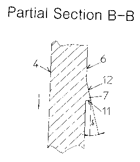
Figure 5 shows the partial cut B-B of Figure 1.
Figure 6 shows detailed view A of Figure 1.
Figure 7 shows a sectional cut of a receptacle with a disk arranged in it.
In Figure 1, a particularly effective and advantageous rotor disk 1 is
represented in
exemplary fashion, with Figure 1 showing the rotor disk from below, i.e. as
seen during operation
from the container bottom 17. In practice, such rotor disks 1 are most often
used in large-volume
CA 02786488 2012-07-06
7
receptacles 2 in which a great amount of polymer material with the
corresponding great weight is
present. A correspondingly great pressure rests on the rotor disk 1. In these
cases, the diameter
of such a rotor disk 1 lies within the range of approximately 2 m and more.
The rotor disk 1 has a disk body 3 on whose top side 4 mixing and/or
comminuting tools
may be arranged. On the opposite underside 6 of the disk body, a number of
conveying ribs 7
extending from the interior to the exterior are arranged. All conveying ribs 7
are curved
concavely in the rotational direction of the disk 1, with the curvatures
running uniformly in the
shape of a circular arc. The curvature radius of the conveying ribs 7 is less
than the radius of the
rotor disk 1 and amounts to about 65 % thereof. Also, the curvatures of all
conveying ribs are
nearly identical relative to each other.
Two groups of coveying ribs 7 are provided, to wit longer and shorter ones,
which are
arranged alternating to each other. The longer coveying ribs 7 start at an
inner circular central
area 14 whose radius is about 30 % of the radius of the rotor disk 1. The
shorter conveying ribs 7
start at an outer central area 15 whose radius is about 5 % of the radius of
the rotor disk 1. All
conveying ribs run continuously all the way to the extreme edge of the rotor
disk 1 or,
respectively, of the disk body 3.
The conveying ribs 7 are not aligned radially relative to the center 8 of the
rotor disk 1.
For example, the outer end sections of all of all conveying ribs 7 are aligned
nearly
tangentially to the outer edge of the rotor disk, to wit at an outer
intersecting angle a of about 140
as measured at the point where the coveying rib 7 reaches the edge or,
respectively, the
circumference between the tangent placed at the extreme edge and the tangent
placed at the
coveying rib 7 where the conveying rib touches the extreme edge or,
respectively, circumference.
The inner initial sections of the longer conveying ribs 7 are oriented
relative to the inner
central area 14 at a first inner intersecting angle 131 of about 150, in each
case measured at the end
point of the conveying rib 7 between the tangent on the inner central area 14
and the tangent on
the conveying rib 7 where it or, respectively, the conveying rib 7 touches the
inner central area
14.
The inner initial sections of the shorter conveying ribs 7 are oriented
relative to the outer
central area 15 at a second inner intersecting angle p, of about 350 to 400,
in each case measured
at the end point of the conveying rib 7 between the tangent on the outer
central area 15 and the
tangent on the conveying rib 7 where it or, respectively, the conveying rib 7
touches the outer
central area 15.
In this case, it will be advantageous if P2 is greater than 131.
CA 02786488 2012-07-06
8
In the contact area at the inner central area 14 and the outer central area
15, the conveying
ribs 7 converge at an acute angle or, respectively, end there.
With conveying ribs 7 designed in that way, large as well as small polymer
particles can
be transported during operation toward the exterior or, respectively, a force
directed towards the
exterior is exerted from the center 8 of the rotor disk 7 upon the particles
grasped by the
conveying ribs 7. As a rule, the conveying effect is brought about by the
mechanical effect of the
conveying ribs 7 on the polymer particles since the treatment usually occurs
in a vacuum. But
treatment under ambient pressure is also possible in the same manner, with
flow effects occurring
in addition to the mechanical contacts between conveying ribs 7 and polymer
particles.
In Figures 2, 3 and 4, the rotor disk 1 is represented in a cross section
through the center
8. On the top side 4 of the disk body 3 facing the container during operation,
mixing and/or
comminuting tools 5 may be arranged. In the embodiment at hand, such tools are
not shown.
The mixing and/or comminuting tools 5 may involve shovels, knives or the like.
They grasp the
polymer particles and bring them into a rotational movement which leads to a
mixing vortex
forming in the container. In addition, the particles are heated and kept in a
constant mixing
process, thereby preventing any adhesion or, respectively, fusing even at
higher temperatures. If
necessary, a shredding or, respectively, comminution of larger granulates will
occur as well.
The conveying ribs 7 are arranged on the underside 6 of the disk body 3. In
this case, the
thickness of the disk body 3 is constant and uniform within an inner area 9.
This inner area 9
extends to about two thirds of the radius of the rotor disk 1. Starting at a
certain distance 18 from
the center 8 of the rotor disk 1, the thickness of the disk body 3 decreases.
In the example at
hand, the radial distance 18 amounts to about 68 % of the radius of the rotor
disk 1. Also starting
from this radial distance 18, the height of the conveying ribs increases
correspondingly towards
the exterior while the height of the conveying ribs 7 is constant and uniform
within the inner area
9.
From Figures 2 through 4 it can be seen that the thickness of the disk body 3
decreases
only to a minor degree, in the embodiment at hand by a mere 2 mm. In the same
manner and to
the same extent, the height of the conveying ribs 7 increases as well,
following their course
towards the exterior so that the overall thickness of the rotor disk 1 remains
the same and uniform
across its entire radius. In this outer area, only the distance between the
disk body 3 or,
CA 02786488 2012-07-06
9
respectively, the underside 6 and the uppermost points or, respectively,
ridges of the conveying
ribs 7 becomes larger or, respectively, the area between the conveying ribs 7
becomes somewhat
higher.
The points or, respectively, areas of the conveying ribs 7 farthest from the
top side 4 form
a level plane 10, with this plane 10 being aligned parallel to the likewise
level top side 4 of the
disk body 3.
In the example at hand, the decrease in the thickness of the disk body 3 runs
continuously
or, respectively, via a slanted plane. The underside 6 of the disk body 3 is
slanted in the outer
area in which its thickness decreases and sloped upward towards the top side 4
at an angle y of
about 0.5 . The rotor disk I or, respectively, the disk body 3 therefore has,
in a manner of
speaking, the shape of a truncated cone with a flattened exterior
circumferential ridge.
In accordance with an additional possible embodiment, the thickness of the
disk body 3
may also decrease continually or, respectively, via steps which entails
advantages in the case of
certain recycling materials.
Moreover, it is provided that at least one hollow space 13 flowed through by a
coolant is
formed in the interior of the disk body 3 through which a cooling effect can
occur on the disk.
In Figure 5, a cross section through a conveying rib 7 is shown. Each
conveying rib 7 has
an essentially triangular cross section, with a conveying surface 11 aligned
level in the direction
of rotation and essentially aligned vertically relative to the underside 6 and
a plane shoulder
surface 12 sloping downward at an angle ö between 10 and 35 , in particular
about 15 ,
downstream relative to the direction of rotation. This achieves the effect in
accordance with the
invention that a particle wedged between the upper edge of the conveying rib 7
and the container
bottom 17 will swiftly become free and slide off via the shoulder surface 12.
This is shown in
detail in Figures 6 and 7.
Figure 6 shows a view of a conveying rib 7 as seen at an angle from the side
of the rotor
disk 1. It can be seen that the shoulder surface 12 does not transition into
the underside 6
continuously, directly or, respectively, at an acute angle but rather via a
ridge or, respectively, a
step 20. However, the transition may also occur without a step 20.
Figure 7 shows a rotor disk 1 in accordance with the invention during
operation, to wit
used in a device for the treatment and conditioning of synthetic material. The
lower left area of
CA 02786488 2012-07-06
such a device is shown in Figure 7. In this case, the rotor disk 1 is placed
in an evacuatable
receptacle 2 which has a level plane, a horizontal bottom surface 17 and
vertical lateral walls 18.
The rotor disk I is arranged in immediate proximity of the bottom and parallel
to the bottom
surface 17 and is supported by a shaft 19 essentially aligned vertically, and
it can also be driven
via this shaft 19. Due to the rotation of the rotor disk I, in particular by
means of the mixing
tools 5, the material present in the receptacle 2 is moved and experiences,
among other things, a
circulatory movement around the axle of the shaft 19.
The distance 21 between the rotor disk 1, to wit between the outermost points
or,
respectively, edges or, respectively, ridges of the conveying ribs 7 or,
respectively the plane 10
farthest from the disk and the bottom surface is relatively small and lies in
the range between
about 5 to 6 mm. The distance 21 between the bottom surface 17 and the rotor
disk 1 is depicted
in Figure 6 schematically and not to scale. The disk having a diameter of
about 2,000 mm usually
rotates at a rotational speed of 10 to 300 revolutions per minute, e.g. at 20
to 150 rpm.
A particularly advantageous embodiment of a device is equipped with an
evacuatable
receptacle 2 with a circular cross section and a vertical axis into which the
synthetic material, in
particular of the thermoplastic kind, e.g. PRT (polyethylene terephthalate),
to be processed is fed
from above through a feed opening in the form of grist consisting of bottles,
bottle pre-moldings,
foils, flakes, etc. If the material to be processed is to be processed in a
vacuum, a lock is attached
to this opening whose lock chamber can be sealed by means of two sliders that
can be moved
back and forth by double-action cylinders. At the top, a feed funnel is
attached to the lock into
which the material to be processed is entered in batches or continuously by
means of a feed
mechanism (not shown), e.g. a conveyor belt. An evacuation line leading to an
evacuation device
is attached to the lock chamber. An additional evacuation line leads from the
receptacle 2 to the
evacuation device.
The receptacle 2 has vertical lateral walls 18 and a horizontal bottom 17.
Near the
bottom 17, a tool carrier is arranged which is formed by a horizontal circular
rotor disk 1 resting
on a shaft 19 which penetrates the bottom 17 in vacuum-tight fashion and which
is driven by a
motor for a rotation in the direction of the arrow. At its surface 4, the disk
bears several tools 5
distributed at equal distances around the circumference of the rotor disk 1
which act on the
synthetic material present in the container 2 during the rotation of the disk
1. On the one hand,
this drives the synthetic material into a circulation around the axis 19, on
the other hand, the
centrifugal force tries to move the synthetic material in a radial direction
towards the lateral wall
CA 02786488 2012-07-06
11
18. A mixing vortex is created to the effect that a portion of the synthetic
material will rise up
along the lateral wall 18, reaching a culmination point during this
circulation and finally falling
back into the area of the container axis. But not the entire amount of the
synthetic material
participates in this uprising because a portion of the synthetic material
hurled off by the disk 1
will try to penetrate into the space below the disk 1, in particular if a lot
of material is present in
the container.
In order to lessen this effect to some degree, the disk 1 in the case at hand
bears several
shovels set at an angle and arranged in equal intervals around the
circumference of the disk.
These shovels impart a preferred upward movement on the synthetic material
hurled off from the
disk 1 by the tools 5, thereby preventing, in a way, synthetic portions from
ending up in the space
below the disk 1 of the tool carrier during the processing of the material in
the container 2.
However, this effect is not optimized until the conveying ribs 7 in accordance
with the
invention are arranged on the underside 4 of the disk 1 which are arranged in
such a way that the
synthetic material ending up or, respectively, pressing into the critical area
is transported in the
direction of the lateral wall 18. The synthetic material moved towards the
exterior in this fashion
will then be grasped by the shovels and be transported upward again.