Note : Les descriptions sont présentées dans la langue officielle dans laquelle elles ont été soumises.
CA 2786529 2017-05-17
FLOOR COVERING WITH INTERLOCKING DESIGN
BACKGROUND OF THE INVENTION
[0001] The present invention relates to surface coverings including floor
coverings. The
present invention more particularly relates to surface coverings, such as
floor coverings having
an interlocking design to connect individual pieces of floor plank or tile
together. The present
invention further relates to methods of makin the surface covering.
[0002] Some of the current surface coverings, such as vinyl floor
coverings, are typically
laid down by placing an adhesive underneath the floor covering or on the sub-
floor or on the
underlayment in order to secure the floor covering. In resilient floor
coverings, a large piece of
resilient floor covering is typically cut in order to fit the dimensions of
the room. The resilient
floor coverings can often be 12-foot wide and can be any length, such as 12
feet, 20 feet, or
longer. With this type of surface covering, it is necessary to adhere the
resilient surface
covering, such as vinyl sheet flooring, to the sub-floor, underlayment or
floor surface in order
to keep the surface covering in place and also to achieve a surface covering
that is level and
does not curl. The installation process of using full-spread adhesive is very
time consuming,
costly, messy as well as cumbersome. For instance, an installer in general has
to do the floor
,
preparation first to remove all oil, dirt, grease, wax, sealers, paint,
adhesives or any other
substances that would hinder installation. In addition, the subfloor must be
level without major
pot holes or cracks; the conditions of the subfloor such as moisture content,
structure
soundness, etc., also have to be taken care of before the adhesive is applied.
On the adhesive
part, the selection of the right type of adhesive based on the type of
subfloor is critical. The
proper tools such as trowel type and its size are important for achieving the
best economics
and performance. After the adhesive is applied, it requires a proper opening
time for the
adhesive to develop its tackiness before the floor is put down. Any residuals
of adhesive
oozing up to the surface of the flooring need to be removed quickly before
they set and adhere
1
o
CA 2786529 2017-05-17
to the flooring surface. Furthermore, the adhesive cost can be quite
expensive. The best
advantage of the floating floor installation is that products can be directly
installed on the
existing floor materials without major prep work or removing the existing
floor. This is a
tremendous benefit for any subfloor for instance, having asbestos content,
where any
disruption of the subfloor structure can be extremely hazardous to the
installer's health.
100031 With all the reasons mentioned above, it should not be a surprise
that the design of
o
floating floors has recently become almost necessary as a surface covering.
For instance,
laminate flooring is used, wherein the laminate flooring typically is a rigid
floor plank that can
be joined together using a mechanical locking system, wherein one side of the
floor plank has
a tongue profile and the adjacent floor plank has a groove profile which
permits the joining of
the two through a mechanical locking system. While this mechanical laminate
flooring system
has gained great popularity in the United States, there are several problems
with this type of
flooring. First, the flooring can be extremely heavy since the core of the
floor plank is
typically made out of a wood-based material, such as a lignocellulosic-resin
composite
material, such as high density fiber board or particle board. Further, this
fiber or particle board
is typically not water resistant and also can be insufficiently resistant to
even humidity
changes. Thus, the laminate flooring can be limited where it is used since if
the wood-based
core became moist and swelled, this would damage the flooring and the laminate
joined floor
planks would actually separate.
100041 While some attempts have been made to provide flooring surfaces made
out of
vinyl that simulate floor planks, these designs have not addressed all of the
problems
associated with previous flooring products, such as the location of adhesives,
failure to use
mechanical locking systems, design features that permit easy joining of
flooring planks
together, and the like. There has been some attempt to use PVC-type floor
panels with a
lockable tongue and groove connection as, for instance, described generally in
U.S. Patent
2
CA 2786529 2017-05-17
Application Publication No. 2008/0138560 and U.S. Patent No. 4,426,820. In the
floor panel
set forth in U.S. Patent Application Publication No. 2008/0138560, only
general designs are
shown in the figures, and there is no clear teaching on precise tongue and
groove profiles with
regard to parameters, such as height, width, angles, and the like regarding
the tongue profile
and groove profile. However, the illustrated figures of tongue and groove
locking designs set
forth in the indicated publication are either based on cantilever hook or
arrowhead designs.
The designs of the indicated publication are believed to have disadvantages in
installation or
joint strength. In the indicated publication, Figure 2a shows a tongue
interlockable with a
sloped land at the end of the bottom side of a groove, wherein the tongue can
be provided with
sufficient thickness to achieve a good joint strength, but it is believed that
the locking design
can require significant effort to force the opening of a relatively narrow
mouth of a groove for
the hook part of the tongue to go in. This process may require using a tapping
block or other
devices with a hammer, which adds complexity for the installer and also
increases the risk of
damaging the product. On the contrary, if the tongue is thin to permit flexing
for ease of
connection, this can result in weak joint strength. In the indicated
publication, Figures 2b, 2c
and 2d show no sloped, inclined land in the groove to restrict the tongue from
sliding apart
from the groove after engagement which can result in a very weak joint
strength. The typical
joint strength of this type of design is less than 5 pounds of force per
linear inch (ph). Figure
2e of the indicated publication is expected to have even more problems for
similar reasons.
[0005] With respect to
U.S. Patent No. 4,426,820, the '820 patent exemplifies a plastic
tongue and groove profile for flooring. The plastic flooring of the '820
patent is made from
hard plastic and is not flexible. The flooring of the '820 patent has tongue
and groove
characteristics similar to many current commercial laminate flooring made from
rigid, high-
density fiberboard or medium-density fiberboard. In the designs of the '820
patent, many
sharp edges in the tongue and groove profiles are used, and this can generate
problems with fit
3
CA 2786529 2017-05-17
during installation. Additionally, the overall strength of the tongue and
groove profiles, when
joined together (joint strength), will be lessened by high stress
concentrations associated with
the sharp edges. In addition, the groove lip top surface plan of the designs
in the '820 patent
are horizontal, which can make insertion of the tongue into the groove
difficult, which can be
an especially important problem when inserting short ends of a panel in the
short ends of an
already engaged adjoining panel. Also, the tongue and groove profiles of the
'820 patent have
a tongue tip cross-sectional area, which is relatively small and can be one-
third the area of
certain embodiments of the present inveptio.p. This is further explained in
the details of the
present invention. Also, the groove deck cross-sectional area in the groove
profile of the '820
patent is disproportionate compared to the tongue tip cross-sectional area,
which engages this
groove deck area. This can be especially important when dealing with thinner
product
applications, such as residential luxury vinyl tiles, wherein the tongue tip
will not provide
enough integrity to facilitate installation if the groove deck cross-sectional
area is
disproportionate to the tongue tip cross-sectional area As shown in the
present invention, a
balanced or proportionate tongue tip cross-sectional area to groove deck cross-
sectional area
will permit overloading of groove voids during insertion, and the tongue and
groove will flex
to accommodate one another and produce a firm product fit. This firm fit
assures stability
through the duration of the installation and for the life of the installed
product. A
disproportionate groove deck area at the tongue tip area will not permit
overloading of the
void. In addition, in various profiles of the present invention, the tongue
profile and/or groove
profile can have slants in various edges as opposed to straight horizontal
edges, which permits
easier insertion of the tongue into the groove and also permits alternative
ways to install the
product (meaning, that the groove can be inserted into the tongue, angle
insertion of one
profile into another is possible, as well as lateral (no angle) insertion).
Thus, with the present
invention, significant improvements over the various tongue and groove
profiles of the '820
4
a
CA 2786529 2017-05-17
patent are achieved, as well as permitting a tongue and groove design that
will provide
sufficient joint strength and operability in a luxury vinyl tile-type product,
as well as other
resilient floor products.
[0006] Furthermore, as described in the present application, not just any
tongue design or
groove design can be used with vinyl-type flooring to achieve acceptable
connecting
properties, such as pull strength or joint strength. The inventors of the
present application
have discovered that particular tongue and groove profiles are necessary in
order to achieve
acceptable pull strengths and other suitable properties which will work with
respect to
resilient-type flooring, such as vinyl 'floc;ring, such as LVT flooring. The
problems
encountered and the solutions achieved by the present invention simply were
not described,
predicted, or appreciated previously. The present invention overcomes these
problems and
provides a surface covering product that is easy to install, requires no
adhesive on the bottom
surface of the surface covering or sub-floor, is water resistant, achieves
acceptable pull
strengths or joint strengths, and/or other connecting properties, and permits
a floating floor that
is relatively lightweight compared to laminate flooring and provides a walking
surface that is
more realistic to solid wood flooring, even from the standpoint of acoustic
sounds.
SUMMARY OF THE PRESENT INVENTION
100071 A feature of the present invention is to provide surface coverings,
such as floor
coverings, that are relatively lightweight, water resistant, or both.
[0008] A further feature of the present invention is to provide surface
coverings, such as
floor coverings, that can be mechanically joined and yet are relatively thin
in thickness.
[0009] An additional feature of the present invention is to provide surface
coverings, such
as floor coverings, that can be mechanically joined and yet are relatively
resilient, light, and
easy to install, and achieve acceptable pull strengths when connected and/or
other connecting
CA 2786529 2017-05-17
properties.
[0010] Another feature of the present invention is to be able to assemble a
surface
covering with resilient plank constructions having mechanically interlockable
tongue and
groove edge profiles on opposite sides of the planks.
[0011] An additional feature of the present invention is to be able to
assemble a surface
covering with resilient rectangular shaped planks with tongue and groove edge
connections
made with elongated tongue lengths to ease installation, application of tongue
and groove
profiles to head-seam joints, enhancement of flexure, enhancement of joint
strength,
enhancement of strength-to-plank thickness, or any combinations of these
features.
100121 Another feature of the present invention is to be able to assemble a
surface
covering with resilient planks with tongue and groove connections as a
floating floor.
100131 Another feature of the present invention is a floor that can be re-
positioned,
removed or replaced without major efforts or destruction of the installed
floor.
100141 Additional features and advantages of the present invention will be
set forth in part
in the description that follows, and in part will be apparent from the
description, or may be
learned by practice of the present invention. The objectives and other
advantages of the
present invention will be realized and attained by means of the elements and
combinations
particularly pointed out in the description and appended claims.
100151 To achieve these and other advantages, and in accordance with the
purposes of the
present invention, as embodied and broadly described herein, the present
invention relates to a
surface covering plank comprising a resilient composite sheet having four
sides, an upper
surface, a lower surface, and an overall thickness, and the composite sheet
comprising at
least one base layer, wherein the at least one base layer comprising at least
one polymeric
material and at least one filler, and opposite sides of the composite sheet
comprise a first
tongue on a first side and a first groove on the opposite second side, wherein
the first tongue
6
CA 2786529 2017-05-17
e =
and first groove have complementary shape to each other to be interlockingly
engageable
with a corresponding groove or tongue on an adjacent floor plank. The surface
covering
plank has one or more of the following features (a)-(d):
(a) the first tongue has a first tongue length (TL) measured between the first
side
of the composite sheet and a distal end of the first tongue. The ratio of the
first tongue
length to the composite sheet overall thickness (CSt) is at least about 1.5;
(b) the composite sheet has a first pair of opposing sides comprising the
first and
second sides that arc shorter than a second pair of opposing sides extending
between the
first pair of sides. The second pair of sides comprise a third side and a
fourth side, wherein
the first groove on the second side is defined between a first flange
extending along a first
edge of the composite sheet and protruding from the second side of the
composite sheet and
a second flange extending along an opposite second edge of the composite sheet
and
protruding from the second side of the composite sheet. The second flange
comprises an
interference that projects in a direction toward a horizontal plane of the
upper surface of the
composite sheet and includes an inclined inner surface defining part of the
first groove,
wherein the first groove is defined between the first and second flanges and
opens toward
the horizontal plane of the upper surface of the composite sheet. A locking
angle defined
between the inclined inner surface of the interference of the second flange
and a horizontal
plane parallel to the lower surface of the composite sheet is from about 55 to
about 65'.
The plank has a flexural force at 0.3" (ph), as determined according to
Modified ASTM
D790, of 1 + 0.35;
(c) the first groove on the second side is defined between a first flange
extending
along a first edge of the composite sheet and protruding from the second side
of the
composite sheet and a second flange extending along an opposite second edge of
the
composite sheet and protruding from the second side of the composite sheet.
The first
7
CA 2786529 2017-05-17
groove includes a groove bottom portion and a minimum groove thickness (Tg) is
defined
between the groove bottom portion and a horizontal plane of the lower surface
of the
composite sheet. The second flange comprises an interference that has a height
(H) that
projects in a direction toward a horizontal plane of the upper surface of the
composite sheet,
and the first tongue comprises a member having a minimum thickness (Tt)
extending from
the first side, and a distal end of the tongue includes a downward extending
projection
comprising a tongue underside and the downward extending projection has a
projection
height (H') from the member, wherein Tg and Tt are within +24% of each other,
H and H'
are within 7% of each other, and wherein a tongue tip thickness (Tt') is
defined as a
shortest vertical distance between the horizontal plane of the upper surface
of the composite
sheet and the tongue underside, whcrein'Tg/Tt' is from about 0.32 to about
0.82;
(d) the first tongue and the first groove are interlockingly engageable with a
corresponding groove or tongue on an adjacent floor plank to have a first pull
strength (ph)-
to-overall thickness (mm) ratio of at least about 2.
[0016] The present invention further relates to a surface covering
comprising a plurality of
individual surface or flooring planks or tiles joined together, such as in the
form of a floating
floor.
100171 The present invention also relates to methods of making and
installing the surface
coverings of the present invention.
[0018] It is to be understood that both the foregoing general description
and the following
detailed description are exemplary and explanatory only and are intended to
provide a further
explanation of the present invention, as claimed.
[0019] The accompanying drawings, which are incorporated in and constitute
a part of
this application, illustrate some of the embodiments of the present invention
and together
with the description, serve to explain the principles of the present
invention.
8
CA 2786529 2017-05-17
o
BRIEF DESCRIPTION OF DRAWINGS
100201 Figs. 1-62 are various schematic drawings depicting the surface
coverings of the
present invention or plank portions thereof from various views. The drawings
are not
necessarily to scale. The drawings represent various design features of the
surface coverings
of the present invention. Similar referencing identifiers in different figures
can refer to
similar features unless indicated otherwise.
10021] FIG. 1 is a perspective top view of a plank according to various
embodiments of
the present invention, wherein edge profiles on the plank are not shown in
this view to
simplify the illustration for the discussion of other features that are shown
therein.
10022] FIG. 2 is an enlarged perspective top view of a plank according to
various
embodiments of the present invention, wherein edge profiles on the plank are
shown in this
view.
[0023] FIG. 3 is an enlarged partial cross-sectional view according to line
I-I in FIG. 1 at a
section medial to sides 3 and 4, wherein the plank is constructed of an LVT
material.
[0024] FIG. 4 is an enlarged partial cross-sectional view according to line
I-1 in FIG. 1 at a
section medial to sides 3 and 4, wherein the plank is constructed of a VCT
material.
100251 FIG. 5 is a cross-sectional view according to line II-II in FIG. 2.
[0026] FIG. 6 is a cross-sectional side view through a plurality of
connected planks of
FIG. 5 according to various embodiments of the present invention.
[0027] FIG. 7 is an enlarged cross-sectional view of a tongued edge shown
with hatched
encircling lines in FIG. 5.
[0028] FIG. 8 is an enlarged cross-sectional view of a grooved edge shown
with hatched
encircling lines in FIG. 5.
[0029] FIG. 9 is an enlarged cross-sectional view of adjacent edges of
planks during
9
CA 2786529 2017-05-17
insertion of a tongued edge of one plank into a grooved edge of an adjacent
plank for
interlocking as shown in FIG. 6.
[0030] FIG. 10 is an enlarged cross-sectional view of adjacent tongued and
grooved edges
of adjacent planks as shown in FIG. 9 prior to installation.
[0031] FIG. 11 is an enlarged cross-sectional view of a plank having
tongued and grooved
edges as shown in FIG. 9.
[0032] FIG. 12 is an enlarged cross-sectional view of a non-grouted square
edge plank
or tile having tongued and grooved edges with other illustrative complementary
profiles.
[0033] FIG. 13 is an enlarged cross-sectional view of a non-grouted square
edge plank
or tile having tongued and grooved edges with other illustrative complementary
profiles.
100341 FIG. 14 is an enlarged cross-sectional view through the edge
portions of
connected grouted planks or tiles having tongued and grooved edges and
defining a grout
,
groove according to various options of the present invention.
100351 FIG. 15 is an enlarged cross-sectional view through the edge
portions of
connected grouted planks or tiles having tongued and grooved edges and
defining a grout
groove according to various options of the present invention.
100361 FIG. 16 is an enlarged cross-sectional view of a square edge plank
having
tongued and grooved edges with other illustrative complementary profiles.
10037] FIG. 17 is an enlarged cross-sectional side view through the edge
portions of
connected planks of FIG. 16 according to various options of the present
invention.
[0038] FIG. 18 is enlarged cross-sectional views of a method of installing
edges of planks
of FIG. 16 for interlocking and unlocking.
[0039] FIG. 19 is enlarged cross-ectional views of a beveled edge plank
having
tongued and grooved edges with other illustrative complementary profiles.
10040] FIG. 20 is an enlarged cross-sectional side view through the edge
portions of
CA 2786529 2017-05-17
connected planks of FIG. 19 according to various options of the present
invention.
[0041] FIG. 21 is enlarged cross-sectional views of a method of installing
edges of planks
of FIG. 19 for interlocking and unlocking.
[00421 FIG. 22 is an enlarged cross-sectional side view of adjacent tongued
and grooved
edges of adjacent planks prior to installation with other illustrative
complementary profiles.
[00431 FIG. 23 is an enlarged cross-sectional side view through connected
planks having
tongue and groove portions as shown in FIG. 22 according to various options of
the present
invention.
[00441 FIGS. 24 and 26 are enlarged cross-sectional views of adjacent
tongued and
grooved edges of adjacent planks prior to installation with other illustrative
complementary
profiles. FIGS. 24 and 26 relate to planks with different thicknesses.
[0045] FIGS. 25 and 27 are enlarged cross-sectional side views through the
edge portions
of connected planks of FIGS. 24 and 26, respectively, according to various
options of the
present invention.
100461 FIG. 28 is an enlarged cross-sectional view of adjacent tongued and
grooved edges
of adjacent planks prior to installation with other illustrative complementary
profiles.
100471 FIG. 29 is enlarged cross-sectional side view through the edge
portions of
connected planks of FIG. 28, according to various options of the present
invention.
[0048] FIG. 30 is an enlarged cross-sectional view of a plank having
tongued and
grooved edges with other illustrative complementary profiles.
[0049] FIG. 31 is an enlarged cross-sectional side view through the edge
portions of
connected planks of FIG. 30 according to various options of the present
invention.
[0050] FIG. 32 is an enlarged cross-sectional view of adjacent tongued and
grooved
edges of adjacent planks prior to instal lation4with other illustrative
complementary profiles.
[0051] FIG. 33 is an enlarged cross-sectional side view through the edge
portions of
11
CA 2786529 2017-05-17
connected planks of FIG. 32 according to various options of the present
invention.
[0052] FIGS. 34 and 36 are enlarged cross-sectional views of adjacent
tongued and
grooved edges of adjacent planks prior to installation with other illustrative
complementary
profiles. FIGS. 34 and 36 relate to planks with different thicknesses.
100531 FIG. 35 is an enlarged cross-sectional side view through the edge
portions of
connected planks of FIG. 34 according to various options of the present
invention.
[0054] FIG. 37 is an enlarged cross-sectional view of a plank having
tongued and
grooved edges with other illustrative complementary profiles.
[0055] FIG. 38 is an enlarged cross-sectional side view through the edge
portions of
connected planks of FIG. 37, according to various options of the present
invention.
[0056] FIG. 39 is a perspective view of a surface covering system according
to various
options of the present invention.
[0057] FIGS. 40-60 are enlarged cross-sectional side views of tongue and/or
groove
e
profiles of the present invention.
10058] FIG. 61 is an enlarged cross-sectional view of a carpet tile having
tongued and
grooved edges according to various options of the present invention.
[0059] FIG. 62 is a perspective view of a test layout for application of a
rolling load to a
grouted LVT plank designed according to various options of the present
invention.
DETAILED DESCRIPTION OF THE PRESENT INVENTION
100601 The present invention relates to surface coverings, such as floor
coverings,
constructed of resilient planks or tiles that can be assembled together by
integral mechanical
connections. Planks alone are often referenced herein for sake of simplifying
the discussion.
The planks can have any dimensions and can be a square or rectangular or other
shapes.
Wherever "planks" of the present invention are referenced herein, the
description thereof can
12
CA 2786529 2017-05-17
be understood to apply equally to "tiles" unless indicated otherwise. The
present planks
comprise a unique combination of resilient core construction and mechanically
interlocking
tongue and groove edge profiles. With the present planks, a surface covering
can be assembled
,
with resilient rectangular shaped planks with tongue and groove edge
connections made with
elongated tongue lengths relative to plank thickness to ease installation. A
longer tongue tip
can provide an improved guide for inserting the tongue to the groove. The
present planks
also have tongue and groove profiles useful for making head-seam joints (that
is, shorter side
joints) between planks. The joint profiles of the present planks, which can
permit a very low
angle of insertion, combined with the flexible nature of the resilient base,
permit the
practical application of this connection to the head seams, i.e., connections
made at shorter
sides of rectangular shaped planks. The edge profiles also can be used on the
side seams of
the planks, i.e., at longer sides of the planks. The present planks also can
provide enhanced
flexure, which can assist installation at head seams, side seams, or both.
Further, the present
planks can provide enhanced joint strength, enhancement of strength-to-plank
thickness, or
combinations of these strength features, between resilient planks. A
significant correlation to
joint pull strength, for example, has been determined to be associated with
providing tongue
and groove edge designs in the present planks which have a minimum groove
thickness and
a minimum tongue tip thickness (total, including any top layer portion) that
are within +24%
of each other. The present resilient plank constructions can provide pull
strength-to-
thickness (pounds force per linear inch (pli)/mm) ratios of at least twice
those determined
for a prior tongue-and-groove plank design having a particle board core and
top layer (print
layer and overlay (wear layer)). The inclusion of one or more of these plank
features is
effective to prevent one connected plank from inadvertently disengaging from
the adjacent
plank under normal use conditions or moving out of place vertically to the
surface plane of
the flooring or other surface covering comprised of an assembly of the planks
with
4 ,4
13
CA 2786529 2017-05-17
interlocked tongue and groove edges.
100611 The present plank
or tile incorporates the edge profile designs in edges of a
resilient composite sheet structure. The composite sheet can be comprised, for
example, of
one or more base layers comprising a homogenous blend of polymer material and
filler in
resilient sheet form. The polymer can be, for example, a thermoplastic
polymer, a thermoset
polymer, or blends of polymers. The filler can be, for example, a particulate
material, which
is dispersible in the polymeric material. The filler can be, for example, an
inorganic filler, an
organic filler, or any combinations of fillers. The polymeric material can
form, for example,
a continuous phase into which the filler is dispersed as a discrete phase. In
another example,
the composite sheet can comprise a laminate structure of diverse material
layers including
one or more base layers (e.g., two or three or more base layers that can be
the same or
different with respect to composition and/or physical properties) comprising a
homogenous
blend of polymer material and filler. The coin poc,ite sheet structure of the
plank can
comprise, for example, a luxury vinyl tile (LVT) material, a vinyl composition
tile (VCT)
material, or a rubber material. Other resilient polymer-containing composite
sheet materials
can be used. The LVT material can further include a top layer, which can
include at least a
printed design and wear layer(s), arranged on top of the base layer or layers.
The VCT
material can optionally have inlaid surface chips, but typically no wear layer
or printed
design is overlying the VCT material. The printed design can be present as a
separate design
layer, can be part of a wear layer or other layer, or can be printed on a
layer, such as a base
layer or other layer. The VCT material, LVT material, or rubber material can
further include
a carpet surface layer to provide a carpet tile or plank. When a carpet
surface layer is
present, a design layer or surface or a printed design or print layer or print
surface, or a wear
layer can be omitted. The carpet layer can be located on a base layer(s) with
or without other
layers as mentioned herein.
14
CA 2786529 2017-05-17
[0062] The present planks and carpet tiles can be installed, for example,
in a modular
manner with mechanical interlocking of the profiled side edges, without need
of separate
adhesive to retain the positions of the planks or tiles on a surface to be
covered. The locking
joint provided in the profiled edges of the present planks and tiles can be
very effective
when applied to flexible and semi-flexible products, such as the LVT material,
VCT
material, or rubber material alone or in combination with other surface
materials such as
carpeting components.
[00631 For purposes herein, a luxury vinyl tile (LVT) refers to a resilient
tile floor
covering comprised of polymeric material and a minor amount (<50 wt%) of
inorganic filler
(based on the total wt% of the LVT). The LVT material can meet the
requirements of
ASTM F 1700, Class III (Printed Film Vinyl Tile). The LVT material can have a
print
design or film applied over a base layer(s) or other intermediate layers with
a clear (e.g.,
vinyl) wear layer(s) on top of the print film. The base layer(s) of LVT can be
comprised of
polymeric material (or "binder"), fillers, and pigments compounded with
suitable lubricants
and processing aids. In LVT, the polymeric material can be present in an
amount of at least
34 wt% polymeric material (or "binder") comprising, for example, one or more
thermoplastic polymers, such as polymers of vinyl chloride, copolymers of
vinyl chloride, or
both, and other modifying resins, and can include plasticizers. Further, the
polymers and
copolymers of vinyl chloride can comprise at least 60 wt% of the polymer
material, and
copolymers of vinyl chloride can comprise at least 85 wt% vinyl chloride. In
various
options, the LVT material can be configured to be non-grouted or grouted. The
LVT
material optionally can include a groove for receiving grout at the upper
surface above
where the profiled edges are mated. The grout can be polymeric (e.g.,
thermoplastic,
silicone, acrylic), cement, cement-like, mortar, mortar-like, or other
materials that can be
used to fill in a void or grout line.
15
CA 2786529 2017-05-17
100641 For purposes herein, a vinyl composition tile (VCT) material refers
to a resilient
tile floor covering material comprised of polymeric binder material and
inorganic filler in a
predominant amount (>50 wt%) based on the total weight of the VCT. The VCT
material
can be comprised of polymeric material (or "binder"), fillers, and pigments.
The polymeric
material can be one or more thermoplastic polymers, such as polymers of vinyl
chloride,
copolymers of vinyl chloride, or both, compounded with suitable plasticizers
and stabilizers.
The VCT material can meet requirements of ASTM F 1066. As indicated, the vinyl
composition tile material can optionally have an inlaid construction at its
upper surface,
which does not change the overall thickness of the sheet product. The inlaid
process can use,
for example, solid colored vinyl chips that are laid on top of a VCT carrier
sheet and then
bonded together with heat and pressure, such as in conventional manner used
for inlaid
process. In various options, the VCT material can be configured to be non-
grouted or
grouted. The VCT material optionally can include a groove for receiving grout
at the upper
surface above where the profiled edges are mated.
100651 In various options, one or more, or all, of the base layers of the
plank or tile of
the present invention can include one or more rubber or elastomer materials
and at least one
filler material. The rubber or elastomer'can' be present in the same amounts
as those given
for the thermoplastic polymer material, such as PVC, described herein. The
rubber or
elastomer can be the primary component (by weight) in one or more, or all,
base layers. As
an option, the rubber or elastomer can be a substitute for the thermoplastic
or PVC
ingredient that can be used in the base layer(s). The rubber or elastomer
component can be
considered a polymer for purposes of the present invention. Rubber-based base
layer(s) of
the present planks or tiles can be comprised of rubber (elastomer), fillers,
and optionally
pigment. The rubber can be, for example, a vulcanizable rubber, a reaction
system
elastomer, a thermoplastic elastomer, or other elastomers. Some filler, such
as carbon black
16
CA 2786529 2017-05-17
or others, also may function like a pigment to impart color to the base
layer(s). The amount
of filler in the rubber-based base layer(s) is not categorically limited, and
can range, for
example, from about 0.1 wt% to about 99 wt%, or from about 1 wt% to about 90
wt%, or
from about 5 wt% to about 80 wt%, or from about 10 wt% to about 75 wt%, or
from about
20 wt% to about 50 wt%, or other amounts, based on the total weight of the
rubber-based
layer(s).
,
[0066] The carpet tiles
can be a laminate structure, for example, which combines a carpet
layer as a surface layer and a substrate comprised of the VCT, LVT, or rubber
materials, or
similar materials, to which the carpeting is attached (where the attaching can
be permanent or
removeably attached to the substrate of the plank). The carpet tiles can
include a carpet layer
which can be any backed or non-backed carpet material, including conventional
carpeting,
which can be attached (e.g., adhesively, mechanically, and so forth) to a
major surface of the
substrate. In some examples, the carpet tile can have a substrate formed of
one or more of
the base layers of VCT, LVT, or rubber material(s) to which is adhesively
bonded or
thermally bonded (e.g., heated press laminated) a carpet layer (e.g., a cut
pile, a loop pile, a
cut and loop, a (print) tufted, and so forth). In the carpet tiles, a locking
tongue and groove
joint, for example, can be profiled into a flexible or semi-flexible base
product (possibly
with substantial recycle content), such as the indicated LVT material, VCT
material, or
rubber material. In view of the mechanical interlockable tongue and groove
system provided
at the profiled edges of the composite structure, the carpet tile does not
need to be adhered
to a floor which it covers to keep the tile(s) in place. The carpet tile can
be a floating floor.
This can provide modular carpet tile flooring which, for example, which is
strongly
connecting and can be easily installed, replaced/repaired, and uninstalled,
while eliminating
the need to use costly adhesives (e.g., some pressure sensitive adhesives) or
difficult to
remove adhesives.
17
CA 2786529 2017-05-17
100671 The present
invention particularly relates to surface coverings, such as floor
coverings, having an interlocking design on at least two sides of planks or
tiles used in the
assembly of the surface covering. The interlocking design permits the
connecting of individual
pieces of the planks or tiles together in length and width directions to form
a surface covering,
such as a monolithic surface covering, without the need for any installation
adhesive
underneath to hold the product together and, further, preferably requires
minimum preparation
work for the sub-floor or sub-surface. The interlocking system used in the
present invention
generally involves a mechanical lock system to provide a durable locking and
holding of the
floor surface. The mechanical locking system can be visible with respect to a
tongue
(projections), also known as the "giving part," and a "receiving part," which
is also known as
a groove (recess). The tongues and grooves can be located parallel to each
other on both pairs
of sides or edges of the surface covering to achieve near-perfect or perfect
alignment. The
tongues and grooves of the mechanical lock can have any geometrical design or
shape that
includes one or more of the indicated features (a) - (d) and/or includes one
or more other
characteristics mentioned herein. The tongue extends outward from the edge or
side of the
plank or tile to have an appropriate width and length. The tongues and grooves
can have
dimensions indicated herein for providing enhanced pull strength when
interfitted. The
grooves of the mechanical lock system can be a complementary cut-out to the
tongue portion.
As an option, the size of the grooves can be slightly larger than the grooves
to allow an easier
interlocking of the tongues into the grooves. The edge of the cut-out or
groove is lined up,
preferably, precisely to the opposite edge or side having a groove as shown in
the Figures. The
thickness of the receiving part or grooves can be identical (or nearly
identical) to the tongue
thickness, so that once they are connected together, there is no ledge or
ridge fonned. As
stated, the tongue and groove interlocking design with one or more of
conditions (a) - (d)
and/or one or more other characteristics mentioned herein, of the present
invention permits
18
CA 2786529 2017-05-17
easy installation. To connect the planks together, a motion, similar to
putting a puzzle
together, can be used. One plank can be connected to the other from end-to-end
and then to
another plank side-to-side, or vice versa, to cover the entire surface of the
room.
[0068] The surface covering of the present invention can be any surface
covering, such as
a floor covering, wall covering, ceiling, and the like. The surface covering
can be used
essentially in any room in a house or work environment, including the kitchen,
bathroom,
living room, dining room, recreation room, garage, and outside living spaces,
such as a porch,
deck, and the like. The surface coverings of the present invention can be used
in an inside or
outside environment, especially since the surface coverings of the present
invention are water
resistant and do not swell when wet. In fact, the thickness swell of the
surface coverings of the
present invention is negligent (e.g., zero or zero to less than 0.01 mm or
0.0001 mm to less
than 0.001 mm) when tested at LF 3.2 of NALFA LF 01-2003.
[0069] For purposes of the discussion below, a preferred embodiment, floor
planks or
floor tiles are described. However, it is realized that this description
equally applies to surface
coverings in general. Furthermore, while the term "floor plank" is used, it is
to be understood
that floor plank includes any geometrical design, especially designs having
four sides, and the
four sides can be rectangular, including squares, and can be any length or
width such that the
floor plank can serve as an elongated, rectangular floor plank or can be floor
tile, which can be
square or a rectangular shape of modular tile format. The present invention is
not limited by
any length or width, nor any geometrical design. Nonetheless, as indicated, a
particular
advantage of the present plank designs is the enhanced ability to manually
interlock head
seams (shorts) on rectangular shaped planks.
[0070] In more detail, the floor plank 10 can have a generally rectangular
shape having
upper and lower surfaces 5 and 6, for instance, as shown in FIG. 1, which
omits the tongue and
groove profiles that extend along sides 1-4 (shown by hatched lines) to
simplify this
19
CA 2786529 2017-05-17
illustration. The tongue and groove profiles are illustrated in other figures
herein. The floor
plank has an overall thickness (CSt). It is noted, for instance, referring to
FIG. 2, that
technically with the presence of tongues 1010 and grooves 1020, the overall
floor plank is not
precisely rectangular due to these additional profiled edge surfaces that
extend from sides of
the plank body 11A. Other than the tongue and groove edge profile portions,
the remaining
plank body 11A can be precisely rectangular. In FIGS. 1 and 2, side 1 and side
2 would be the
opposing short sides, and side 3 and side 4 would be the opposing long sides,
and when
compared to each other. (It is to be appreciated that the plank can be a
square (not shown) with
two sides having a groove profile and two sides having a tongue profile of the
present
invention.) The plank 10 is a composite sheet 11 that has a top surface 12 and
a bottom surface
14. The top surface 12 is the surface of the plank that is seen when the plank
is installed as a
surface covering, and the bottom surface 14 can directly rest on a surface to
be covered by the
plank or on a subflooring that directly rests on such a surface. As also shown
in FIG. 2,
grooved sides 2 and 4 of the plank 10 can include a two-way cut-out portion 21
in the flange or
interference 1040 that extends along each of sides 2 and 4 at a corner of the
plank where these
grooved sides intersect. The two-way cut-out portion 21 permits a tongue 1010
of another
similar plank to be inserted in an unobstructed manner into a groove 1020 at
either of sides 2
or 4, while a significant length of a flange or interference 1040 remains at
the grooved sides
for interlocking with the tongue 1010 when inserted in the groove 1020.
100711 The plank or tile
can be formed with two pairs of opposing sides (e.g., 1-2 and 3-
4) wherein the pairs of sides can be the same or different in length relative
to each other. In
one example, the plank is rectangular. The width or shorter sides of the
rectangular plank
can be, for example, at least about 10%, or at least about 20%, or at least
about 33%, or at
least about 50%, or at least about 75%, or at least about 100% smaller, or at
least about
200% smaller, or at least about 500% smaller in dimension than the length
dimension of the
CA 2786529 2017-05-17
plank. The rectangular plank can have opposite shorter sides having a width,
for example, of
from about 2 cm to about 60 cm, or from about 5 cm to about 30 cm, or from
about 10 cm to
about 25 cm, or other widths, and opposite longer sides having a length, for
example, of
from about 5 cm to about 300 cm, or from about 25 cm to about 225, or from
about 35 cm
to about 150 cm, or from about 50 cm to about 100 cm, or from about 60 cm to
about 80
cm, or other lengths. As indicated, the plank also may be square shaped, and
have four sides
of equal length. In some examples, surface coverings of the present invention
can be, for
example, square shaped tiles, such as carpet tiles. The sizes of the present
carpet tiles are not
necessarily limited with respect to larger sizes other than possibly by
practical considerations
such as respect to handling, etc. The smaller sizes of the tiles should
adequately allow for the
formation and use of the profiled edges on the tile. In some examples, for any
plank or tile of
the present invention, the tiles have square shapes with a side length of from
about 2 cm to
about 300 cm, or from about 15 cm to about 200 cm, or from about 20 cm to
about 125 cm, or
from about 25 cm to about 100 cm, or from about 25 cm to about 80 cm, or from
about 30 cm
to about 65 cm, or from about 35 cm to about 50 cm, or other side lengths.
[0072] As illustrated in
FIGS. 3 and 4, the composite sheet (11A, 1113) has significant
portions of the top and bottom surfaces 12 and 14 that are generally
horizontally planar and
extend parallel to each other. In one example, at least about 50%, or at least
about 60%, or at
least about 80%, or at least about 90%, or at least about 95%, of the top and
bottom surfaces
are flat or relatively flat surfaces. It is to be understood that a relatively
flat surface can
include a textural or embossed surface, where the embossed surface can be in
registered with
the print design, and can be achieved mechanically and/or chemically. The
plank comprises a
resilient composite sheet having at least one base layer (31A-C or 21) that
comprises at least
one polymeric material and at least one filler (e.g., inorganic filler). FIG.
3 illustrates a
section of a present plank where composite sheet 11A comprises a laminate
construction
21
CA 2786529 2017-05-17
include base layer portion 31. Base layer 31 comprises at least one base
layer, such as three
base layers 31A-31C, and a top layer 33. The hatched lines 310 and 311
indicate original
interfaces of the stacked sublayers, which may or may not be visible in the
finished laminate,
depending in part on the coloring or hues of the various sublayers. Top layer
33 comprises a
print design 35 and a wear layer or overlay 37. The top layer 33 is integrally
attached to an
upper surface 312 of the base layer 31. The top layer also optionally can have
an underlay (not
shown) below the print design and a protective layer (not shown) on the wear
layer. The top
layer(s) can be, for example, PVC, olefins, urethane, ionomer, acrylic,
polyester, thermoplastic
polyolefin (TPO), thermoset polyurethane (TPU), or other materials
conventionally used for
this type of layer(s) or materials such a illvstrated herein. The protective
layer can be, for
example, a thermally cured system such as water based polyurethane dispersion
system, water
based acrylic, or vinyl emulsion coating, or a radiation cured coating system
such as urethane
epoxy or polyester acrylates, or other materials conventionally used for this
type of layer or
materials such as illustrated herein. One or more of the base layers 31A-C can
be formed, for
example, of LVT-based material, VCT-based material, rubber-based material, or
other
polymeric materials in combination with filler. In another option, layer 37
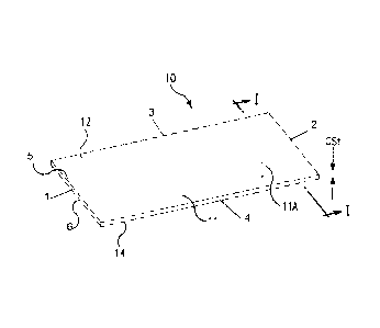
can be replaced by a
carpet layer and layer 35 can be replaced by an adhesive layer which bonds the
carpet to the
base layer 31. FIG. 4 illustrates a section of a present plank comprising
composite sheet 11B
including VCT material layer 21 and an optional inlaid chip surface region 23.
100731 FIG. 5 shows
further details of the tongue profile portion 101 (side 1) and groove
profile portion 102 (side 2) of the plank 10 shown in FIG. 4 from a cross-
sectional
perspective. The tongue 1010 and groove 1020 are located on opposite sides 1
and 2 of the
plank 10. The plank 10 is constructed of a composite sheet 11, which can have
a structure
such as the indicated LVT composite sheet 11A of FIG. 3 or a VCT composite
sheet 11B of
FIG. 4, or other composite sheet structures.
22
CA 2786529 2017-05-17
[0074] FIG. 6 shows the plank 10 in a mechanically interlocked
arrangement with an
identical plank design, plank 10 ' , at adjacent tongue and groove edges. The
surface
covering planks 10 and 10' used in this surface covering have one or more of
the indicated
=
features (a) - (d) and one or more of other characteristics mentioned herein.
[0075] FIG. 7 shows the tongue 1010 has a tongue length TL, as
measured between the
tongue channel wall 110 and a distal tip 112 of the tongue 1010 of the
composite sheet
forming the plank 10. The ratio of the tongue length TL to the composite sheet
overall
thickness (CSt) can be, for example, at least about 1.5, or from about 1.5 to
about 2.0, or
from about 1.7 to about 1.9. As indicated, planks made with elongated tongue
lengths relative
to plank thickness can ease installation and a longer tongue tip can provide
an improved
guide for inserting the tongue to the groove. The tongue can have any length
(TL), such as,
for example, from about 1.5 mm to about 50 mm or more, for instance, from
about 3 mm to
about 20 mm, or from about 5 mm to about 15 mm, or from about 8 mm to about 13
mm, or
from about 9 mm to about 12 mm. As indicated, Fig. 7 illustrates how the
length TL of thc
tongue is measured.
[0076] The plank can have a thickness (CSt), for example, of
from about 2 mm to about
40 mm, or from about 2.5 mm to about 20 mm, or from about 3 mm to about 10 mm,
or
from about 3.5 mm to about 8 mm, or from about 3.9 mm to about 6 mm, or from
about 4.0
mm to about 5 mm, or from about 4.2 to about 4.6 mm, or other thicknesses. The
fabrication
of tooling suitable to profile edges of the plank according to the present
plank designs may
encounter practical considerations where the plank thickness becomes very
small or very
large.
[0077] FIG. 8 shows the groove 1020 defined between a first
flange 1030 and a second
flange 1040 extending along opposite edges 202 and 204 of side 2 of surfaces
12 and 14 of
the composite sheet 11 and protruding horizontally from side 2 of the
composite sheet 11
23
CA 2786529 2017-05-17
forming the plank. The second flange' 1040 comprises an interference of height
H that
projects in a vertical direction toward a horizontal plane HP of the upper
surface 12 of the
composite sheet 11. The second flange 1040 includes an inclined inner surface
1044
defining part of the groove 1020. The groove 1020 opens toward the horizontal
plane HP of
the upper surface 12 of the composite sheet 11. A locking angle "A" is defined
between
inclined inner surface 1044 of the second flange 1040 and a horizontal plane
HP' that
extends parallel to the lower surface 14 of the composite sheet 11. Angle A
can be, for
example, from about 55 to about 65 , or from about 57.5 to about 62.5 , or
from about
59 to about 61 , or other angles.
100781 The plank 10 also has flexure property that can ease interlocking of
adjacent
planks. The plank can have a flexural force, for example, at 0.3" (ph), as
determined
, a
according to Modified ASTM D790, of at least 0.5, at least 0.75, at least 1,
at least 1.25, at
least 1.5, at least 1.75, at least 2, at least 2.25, at least 2.5, at least
2.75, at least 3, at least
3.25, at least 3.5, at least 3.75, for example, 3 0.75, or 2 0.50, or 1.5
0.45, or 1 0.35.
As indicated, the present planks have enhanced flexure, which can assist
installation at head
seams, side seams, or both. For example, the plank has a composite sheet
structure which
can bow or flex sufficient to facilitate making an engagement of a tongued
edge of one
plank with a grooved edge of another plank.
100791 FIG. 9 shows a method of interfitting adjacent tongue and groove
edges of
planks 10 and 10' shown in FIG. 6 for interlocking them. The planks 10 and 10'
arranged
on a surface body 90, such as a floor, to be covered with planks. The surface
body 90 has an
upper surface 901 upon which the planks will rest in an interfitted manner.
Surface 901 can
be generally flat. The tongue 1010 of plank 10 is introduced into groove 1020
of plank 10'
at an insertion angle "Aol". The insertion angle Aol is the angle of tilt that
can be applied to
plank 10 by rotating the plank surfaces 12 and 14 counterclockwise RT1
sufficient to allow
24
CA 2786529 2017-05-17
insertion, such as manual insertion, of tongue 1010 into groove 1020 of plank
10' with
,
translation of the plank 10 in a direction Dl. The amount of tilt imparted to
plank 10 is also
indicated by the upward deflection of the upper surface 12 of plank 10 away
from its
original horizontal plane HP, such as shown by its deflected plane IP. The Aol
can be, for
example, from about 2.5 to about 90", or from about 30 to about 45 , or from
about 3 to
about 25 , or from about 5 to about 25 , or from about 7.5 to about 15 .
After tongue 1010
is inserted into groove 1020 of plank 10 ' , then the upper and lower surfaces
12 and 14 of
plank are rotated downward in a clockwise direction RT2 downward until the
lower surface
14 comes to rest on surface 901. At that point, the planks 10 and 10' have
mechanically
interlocked tongue and groove portions 101 and 102, such as shown in FIG. 6.
The joint
profiles of the present planks, which can permit a very low angle of
insertion, combined
with the flexible nature of the resi4nt µbase, permit the practical
application of this
connection to the head scams, i.e., connections made at shorter sides of
rectangular shaped
planks. The edge profiles also can be used on the side scams of the planks,
i.e., at longer
sides of the planks.
100801 FIG. 10 is an
enlarged cross-sectional view of adjacent tongue and groove
portions 101 and 102 of adjacent planks 10 and 10' shown in FIG. 9 showing
some tongue
and groove features in more detail. As indicated, these planks are composite
sheet
structures, such as illustrated herein but not limited thereto. In this
illustration, the planks 10
and 10' have overall thickness Cst, and respective tongue and groove portions
having
square edges 221 and 222 at their upper approaching edge surfaces. With
respect to the
grooved portion 102 of plank 10 ' , the groove 1020 on side 2 of plank I 0 '
is defined in part
by a groove landing or bottom portion 1021' located between flange 1030
extending along a
first edge 1038 and a flange 1040 extending along an opposite edge 1039 of the
plank 10 ' .
A groove wall 1023 extends upwardly between the groove landing 1021 and a deck
22. The
CA 2786529 2017-05-17
groove wall 1023 is curved, slanted, or both at least in part relative to
plane HP. The groove
landing 1021 can be sloped or extend ,par411e1 relative to plane HP '(or HP).
The groove
landing 1021 is illustrated with a slope relative to plane HP in FIG. 10. When
the groove
landing 1021 has a slope relative to plane HP', such as illustrated in FIG.
10, the inclined
land in the groove can further restrict the tongue from sliding apart from the
groove after
engagement, which can result in a stronger joint strength. The groove landing
1021 can
comprise a planar surface that is sloped or parallel to plane HP ' . A minimum
groove
thickness (Tg) is defined as the shortest vertical distance between the groove
landing 1021
and the horizontal plane HP' of the lower surface 14 of the plank 10 ' . The
flange 1040
comprises an interference 1041 having a height (H) that projects in a
direction toward the
horizontal plane HP of the upper surface 12 of the plank 10 ' . The flange
1040 has a lip
landing 1042 defining its upper surface. The lip landing 1042 can be sloped or
extend
parallel relative to plane HP '(or HP).' The lip landing 1042 is illustrated
with a slope
relative to plane HP' in FIG. 10. The lip landing 1042 can be a planar
surface. Interference
height (H) is defined as the shortest vertical distance between lip landing
1042 and a
horizontal plane HP" parallel to plane HP' that coincides with minimum groove
thickness
(Tg). The lip landing 1042 forms an edge 1043 with sloped or slanted wall 1044
of
interference 1041 that in part defines groove 1020. As indicated, the grooved
portion 102
also has a deck 22 having a length (Dg) that extends in a generally normal
orientation to
upper surface 12 and plane HP.
[00811 In FIG. 10, with
respect to the tongued portion 101 of plank 10, the tongue 1010
comprises a member 1011 protruding from side 110 of the plank 10. The tongue
1010 has a
minimum thickness (Tt) located in a downward facing recess 1016 defined by a
recess wall
1019, wherein the minimum thickness (it) is defined as the shortest vertical
distance
between the recess wall 1019 and the horizontal plane HP of the upper surface
12 of the
26
CA 2786529 2017-05-17
plank 10. A distal end portion 1012 of the tongue 1010 includes distal tip 112
and a
downward extending projection 1013 of height (H') from the member 1011. The
underside
1015 of the tongue distal end portion 1012 an be sloped or extend parallel
relative to plane
HP. The tongue underside 1015 can be a planar surface. The tongue underside
1015 is
illustrated with a slope relative to plane HP in FIG. 10. A tongue tip
thickness (Tt') is
defined as a shortest vertical distance between the horizontal plane HP of the
upper surface
12 of the composite sheet 11 and the tongue underside 1015. If tongue
underside 1015 and
recess wall 1019, in the alternative, are not sloped and extend parallel to
plane HP, then Tt
and H' have respective constant values and those values in combination
correspond to the
shortest vertical distance between plane HP and tongue underside 1015 to
define the tongue
tip thickness (Tt'). The tongue 1010 of plank 10 also includes a forward
vertical abutment
220, which can abut or come into close proximity to opposing deck edge 22 of
groove
portion 102 of plank 10' when the tongue and groove portions of the planks are
interlocked.
The tongue distal end portion 1012 also has an upper slanted or sloped surface
1017
(relative to plane HP) that extends between abutment 220 and tip 112. The
recess wall 1019
of the tongue 1010 can be sloped or extend parallel to plane HP. The recess
wall 1019 has a
slope relative to plane HP as illustrated in FIG. 10. The tongue 1010 also has
a tongue
length (TL) as indicated in FIG. 7, and reference is made thereto.
[0082] In embodiments of the present planks comprising composite sheets,
such as
illustrated (but not limited to) in FIGS. 7, 10, 12-16, and 61, wherein the
plank can be, for
example, a vinyl product or vinyl compositional product (e.g., a LVT-based
product, or a
VCT-based product, or a carpet tile which incorporates VCT-based product or an
LVT-
based product as a substrate component thereof), or similar construction, or a
rubber product
or a carpet tile which incorporates a rubber product as a substrate component
thereof, at
o A
least one, or two or more, or three or more, or all four of the following
conditions (i), (ii),
27
CA 2786529 2017-05-17
(iii), and (iv) can be met in the plank design:
(i) the ratio of the tongue length TL to the composite sheet overall thickness
(CSt) can be, for example, at least about 1.5, or from about 1.5 to about 2.0,
or from about
1.7 to about 1.9;
(ii) Tg and Tt can be, for example, within +24%, or within 20%, or within
+15%, or within +10%, or within +7.5%, or within 5%, or within 4%, or within
+3%, or
within +2%, or within 1%, or within +0.5%, of each other;
(iii) H and H' can be, for example, within +7% within +5%, or within +4%, or
within +3%, or within +2%, or within +1%, or within +0.5%, of each other;
(iv) Tg/Tt' can be, for example, from about 0.32 to about 0.82, or from about
0.44 to about 0.82, or from about 0.50 to about 0.82, or from about 0.60 to
about 0.82, or
from about 0.65 to about 0.80, or from about 0.70 to about 0.76, or from about
0.72 to about
0.75.
100831 With reference to
FIG. 11, some of the indicated tongue and groove features of
the plank 10 (or plank 10 ' ) shown in FIGS. 5-10 are discussed further. With
respect to the
tongued portion 102 (side 1) of plank 10 (or 10 ' ), the tongue 1010 is
elongated for ease of
installation and resistance during loading, such as illustrated by the TL
values disclosed
herein. The sloped or slanted underside 1015 of tongue 1010 (relative to plane
HP) can
reduce the angle of insertion and can assist in increasing the tongue length
(TL) to enhance a
firm fit between tongue and groove. The angle of slope or slant between tongue
underside
1015 and plane HP (shown in FIG. 11 as a plane HP* that is parallel to plane
HP) can be,
for example, an angle ai of from 0.10 to about 5', or from 0.5 to about 4 ,
from 1.50 to
about 3.50, from 1.8' to about 3 , from 2 to about 2.5 . As indicated, as an
alternative, the
tongue underside 1015 can extend parallel to plane HP 'without a slope or
slant relative
thereto. As indicated, the recess wall 1Q19 a the tongue 1010 can be non-
sloped, or sloped
28
CA 2786529 2017-05-17
or slanted (relative to plane HP). To help accommodate an inclination or slope
in the groove
landing lip 1042, the recess wall 1019 of the tongue 1010 can be sloped or
slanted (relative
to plane HP) in a conforming manner relative to groove landing lip 1042a. If
sloped, the
angle of slope or slant of recess wall 1019 and plane HP (shown in FIG. 11 as
a plane HP*
that is parallel to plane HP) can be, for example, an angle a4 of from about
0.10 to about 5',
or from about 0.5 to about 40, or from about 1.5 to about 3.5 , or from
about 1.8 to about
3 , or from about 2 to about 2.5 . As indicated, as an alternative, the
recess wall 1019 can
extend parallel to plane HP without a slope or slant relative thereto, wherein
angle a.,4 is 00
for that non-sloped configuration. Tongue channel wall 110 can be setback for
expansion.
100841 With respect to
the grooved portion 101 (side 2) of the plank 10 (or 10 ' ) , the
sloped or slanted groove landing 1021 (also considered the lower groove
landing or part of
the proximal groove lower lip) can provide an enhanced guide to the tongue
during locking
mode and resistance during a decoupling mode. The angle of slope or slant
between groove
landing 1021 and plane HP' (shown in FIG. 11 as a plane HP* that is parallel
to plane
HP ' ) can be, for example, an angle az of from about 0.1 to about 7 , or
from about 0.5 to
about 5 , or from about 1.5 to about 4 , or from about 2' to about 3.5 , or
from about 2.5 to
about 3 . As indicated, as an alternative, the groove landing 1021 can extend
parallel to
plane HP' without a slope or slant relative thereto. As indicated, the groove
lip landing
(e.g., 1042 in FIG. 10) can be non-sloped, or sloped or slanted (relative to
plane HP ' ). If
sloped, as shown in FIG. 11, the sloped or slanted groove lip landing 1042a
(also considered
the upper groove landing or part of the distal groove lower lip) can provide
an enhanced
guide to the tongue during lock and can reduce the angle of insertion. If
sloped, the angle of
slope or slant between groove lip landing 1042a and plane HP' (shown in FIG.
11 as a
plane HP* that is parallel to plane HP ' ) can be, for example, an angle a.3
of from about 0.1
to about 5 , or from about 0.5 to about 4 , or from about 1.50 to about 3.5 ,
or from about
,
29
CA 2786529 2017-05-17
1.8 to about 3 , or from about 2 to about 2.5 . As indicated, as an
alternative, the lip
landing 1042a can extend parallel to plane HP' without a slope or slant
relative thereto,
wherein angle a3 is 0 for that non-sloped configuration. Edge 1043a (upper
edge) can be
"sharp", e.g., form an intersection angle f3 between lip landing 1042a and
interference wall
1044 that can be, for example, between.abaut 85 to about 135', or from about
90 to about
120 , or from about 90 to about 115 , or other angle values, to provide
enhanced resistance
for making a forced fit between the tongue and groove. The edge 1043a can be
rounded as
an option, for instance, as shown in FIG. 48. The groove deck 22 can provide
resistance to
the tongue during lock to provide a firm fit and resistance during loading.
The deck
overhang, for example, can provide resistance to the tip of the tongue when
force is
applied. Additional deck overhang (e.g., approximately +0.009" or more) on the
groove
profile can be provided with the present groove and deck design. In addition,
a larger
overhang can be needed or helpful to provide room for beveling on certain
plank products,
such as the beveled edge planks illustrated elsewhere herein. The plank
product preferably
show no signs of failure after 2,554 cycles under rolling load (the load was
165 lbs on a
single caster), wherein the planks were floated over a rough piece of plywood.
In addition,
the pull strength for these plank designs has been measured in excess of 20
ph. In addition
to the performance achievements, the groove deck thickness also can help to
provide the
resistance for a mild force fit and mild resistance to disengagement.
[0085] Further, a significant correlation to joint pull strength has been
determined to be
associated with providing tongue and groove edge profiles in the present
planks of
composite sheet structure and designs having a minimum groove thickness (Tg)
and
minimum tongue tip thickness (Tt) that are substantially similar (e.g., within
+24% or lower
values). The tongue and the groove of the present planks, such as illustrated
as tongue 1010
and groove 1020 in FIG. 10, can be interlockingly engageable with a
corresponding groove
30
CA 2786529 2017-05-17
or tongue on an adjacent floor plank to have a first pull strength (pli)-to-
overall thickness
(mm) ratio of at least about 2, or at least about 2.25, or at least about 2.5,
or at least about
2.75, or at least about 4, or at least about 5, or at least about 6, or from
about 2 to about 6, or
from about 2.25 to about 5.25, or from about 2.75 to about 4. For purposes of
the present
application, pull strength is determined with International Standard test
method ISO 24334
,
("Laminate floor coverings - Determination of locking strength for
mechanically assembled
panels"). In one example, the pull strength of the present planks can be from
about 5 ph i to
about 35 ph, or from about 7.5 ph i to about 30 ph, or from about 11 ph i to
24 pH, or other
values.
(00861 The tongue and groove edge profiles such as shown for the planks in
FIGS. 2-42
are merely illustrative. The resilient planks can be configured at the edge
profiles to have other
suitable geometries and dimensions, as long as the planks incorporate one or
more of the
present conditions a), b), c), and d) (or one or more of conditions (i), (ii),
(iii), and (iv)). FIGS.
12-15, 16, 19, 22, 24, 26, 28, 30, 32, 34, 35, 37, 38, 39 and 41 show
additional exemplary
measurements for tongue and groove edge profiles of the present planks. FIGS.
17, 20, 23, 25,
27, 29, 31, 33, and 36 show the tongue and groove edge portions of some of
these indicated
a
figures in an interlocked arrangement.
100871 FIG. 12 shows a present plank or tile la having an opposite tongue
profile 101 and
a groove profile 102. In FIG. 12, the identified dimensions can have the
following values: CSt
= 0.118 inch (3.0 mm), TL - 0.272 in., Tg = 0.045 in., H = 0.028 in., Dg =
0.015 in., angle 0 =
28 , angle az = 3 , angle f3 = 63 , G7 = 0.058 in., G8 = 0.067 in., G9 - 0.157
in., G10 = 0.073
in., G11 = 0.045 in., Tt = 0.045 in., angle cu = 2', H' = 0.028 in., Tt' =
0.067 in., angle 01 =
26 , angle 02 = 29 , angle 03 = 63 , angle 04 = 95 , T1 = 0.058 in., T2 =
0.016 in., and T4 =-
0.157 in. In FIG. 12, the absolute value of (1-Tt/Tg) = (1 - 0.045/0.045) =
0%. Thus, in this
illustration, Tt and Tg are within +24% of each other. The absolute value of
(1-H/F1') = 1 -
31
CA 2786529 2017-05-17
0.028/0.028 = 0%. Thus, in the illustration, H and H' are within +7% of each
other. The value
of Tg/Tt' = 0.045/0.067 = 0.67. Thus, the value of Tg/Tt' is in the range of
about 0.32 to about
0.82. The value of TL /CSt = 2.30. Thus, the value of TL/CSI is at least 1.5.
Any one or more
of these values in FIG. 12 can be 15%, +10%, or 120% from the values stated
herein.
100881 FIG. 13 shows a present plank or tile lb having an opposite tongue
profile 101 and
a groove profile 102. In FIG. 13, the identified dimensions can have the
following values: CSt
,
= 0.158 inch (4.0 mm), TL = 0.272 in., Tg = 0.058 in., H = 0.028 in., Dg =
0.026 in., angle 0 =
330, angle az = 3 , angle [3 = 63 , G7 = 0.058 in., G8 = 0.093 in., G9 = 0.157
in., G I 0 = 0.099
in., Gil = 0.060 in., Tt = 0.060 in., angle al = 2 , H' = 0.028 in., Tt' =
0.093 in., angle 01 = 31 ,
angle 02 = 34 , angle 03 = 63", angle 04 =95 , Ti =0.058 in., T2 = 0.027 in.,
and T4 = 0.157
in. In FIG. 13, the absolute value of (1-Tt/Tg) = (1 - 0.060/0.058) = 3.4%.
Thus, in this
illustration, Tt and Tg are within 24% of each other. The absolute value of
(1-H/H1) = 1 -
0.028/0.028 = 0%. Thus, in the illustration, H and H' are within +7% of each
other. The value
of Tg,/Tt' = 0.058/0.093 = 0.63. Thus, the value of Tg/Tt' is in the range of
about 0.32 to about
0.82. The value of TL /CSt = 1.72. Thus, the value of TL/CSt is at least 1.5.
Any one or more
of these values in FIG. 13 can be +5%, 10%, or 120% from the values stated
herein.
10089] As indicated, the tongue and groove locking joint designs of the
present
invention also arc applicable to grouted plank and tile, such as grouted LVT
laminate planks
or tiles (e.g., simulated wood flooring LVT laminates) and grouted VCT planks
or tiles, and
other present composite sheet materials. The VCT, LVT, or rubber plank or tile
material, for
example, can include a groove for receiving grout at the upper surface above
where the
profiled edges are mated. The grout groove width or gap, as defined and
measurable when
adjoining planks or tiles are mated, is not necessarily limited, as long as
the size of the gap
does not compromise the viability of the tongue and groove interlock. The
groove width or
gap can be, for example, from about 0.05 in. to about 1 in., or from about 0.1
in. to about
32
CA 2786529 2017-05-17
0.75 in., or from about 0.12 to about 0.6 in, or from about 0.15 in, to about
0.5 in., or from
about 0.2 to about 0.4 in., or from about 0.22 in. to about 0.3 in., or other
values. The depth
of the grout groove in relation to the plank or tile thickness, for example,
can be, for
example, from about 5% to about 50%, or from about 10% to about 45%, or from
about
15% to about 40%, or from about 20% to about 30%, or other values.
[0090] FIG. 14 shows interlocked grouted planks or tiles lc, each having an
opposite
tongue profile 101 and a groove profile 102, and a 1/8 in. wide grout groove
141 defined at the
mating surfaces. The grout 142 can partially or completely fill the groove
141. The grout can
comprise any conventional or other suitable grouting composition, and can be
applied in any
conventional or suitable manner. In FIG. 14, the identified dimensions can
have the following
values: CSt = 0.158 inch (4.0 mm), M1 = 0.125 in., Tg = 0.049 in., TL = 0.272
in., H and H'
are within 7% of each other, Tt = 0.081 in, Tt' = 0.109 in., M2 -- 0.040 in.,
M3 = 0.118 in.,
M4 = 0.120 in., M5 = 0.062 in., M6 - 0.262 in., M7 = 0.063 in., M8 = 0.118 in,
and M9 =
0.055 in. In FIG. 14, the value of Tg/Tt' = 0.049/0.109 = 0.45. The value of
TL /CSt = 1.72.
The absolute value of (1-Tt/Tg) = (1 - 0.081/0.049) = 65%. In this grout
option illustration, Tt
and Tg are greater than 24% of each other. Any one or more of these values in
FIG. 14 can be
+5%, +10%, or +20% from the values stated herein.
[0091] FIG. 15 shows interlocked grouted planks or tiles ld, each having an
opposite
tongue profile 101 and a groove profile 102, and a 1/4 in. wide grout groove
141 defined at the
mating surfaces. The grout 142 can partially or completely fill the groove
141. In FIG. 15, the
identified dimensions can have the following values: CSt = 0.158 inch (4.0
mm), M1 = 0.250
in., Tg = 0.049 in., TL = 0.272 in., H = 0.028 in., H' is within +7% of H, Tt
= 0.081 in, Tt' =
0.109 in., M2 = 0.040 in., M3 = 0.118 in., M4 = 0.183 in., M5 = 0.125 in.,.M6
= 0.324 in., M7
= 0.125 in., M8 = 0.118 in, M9 = 0.055 in., MIO = 0.011 in., and G6 is 0.077
inch. In FIG. 15,
the value of Tg/Tt' = 0.049/0.109 = 0.45. Thus, the value of Tg/Tt' is in the
range of about 0.32
33
,
CA 2786529 2017-05-17
to about 0.82. The value of TL /CSt = 1.72. The absolute value of (1-Tt/Tg) =
(1 -
0.081/0.049) = 65%. In this grout option illustration, Tt and Tg are greater
than 24% of each
other. The grouted plank or tile option of the present invention also can meet
at least one of the
indicated conditions (a)-(d), other than a difference with respect to
condition (e) wherein the
grouted option does not need to meet the requirement of Tg and Tt being within
+24% of each
other, but can meet the other (c) conditions. Thus, the grouted option can
meet condition (a),
or condition (b), or condition (d), or condition (e) with the above noted
modification, or any
combination of these conditions. Any ohe Or more of these values in FIG. 15
can be +5%,
10%, or +20% from the values stated herein.
100921 FIG. 16 shows a present plank 10 having an opposite tongue profile
101 and a
groove profile 102. In FIG. 16, the identified dimensions can have the
following values: CSt =-
0.158 inch (4.0 mm), Tg = 0.061 in., Tg(maximum) = 0.067 in., H = 0.037 in.,
Dg = 0.024 in.,
GI = 0.207 in., angle 0 = 33.49 , angle az = 3.22 , angle co = 2.00', angle a5
= 5.00 , angle
= 63.10 , G4 = 0.088 in., G5 = 0.078 in., G6 = 0.100 in., G7 = 0.041 in., Tt =
0.054 in., Tt
(max) = 0.057 in., angle 04 = 1.89 , angle at = 2.00 , H' ¨ 0.037 in., Tt' =
0.089 in., TL = 0.270
in., angle 01 = 33.08', angle 02 = 31.08 , angle 03 = 63.00 , angle 04 = 95.00
, Ti = 0.056 in.,
and T2 = 0.025 in. In FIG. 16, the value of ( I -Tt/Tg) = (1 - 0.054/0.061) =
11.4%. Thus, in
this illustration, Tt and Tg are within about 12% of each other. The value of
(1-H/H') = 1 -
µ
0.037/0.037 = 0%. Thus, in the illustration, H and H are within 0% of each
other. The value of
Tg/Tt' = 0.061/0.089 = 0.685. The value of TL /CSt = 1.71. FIGS. 49 and 50
show examples
of other values for these measurements.
100931 FIG. 17 shows the tongue profile 101 and groove profile 102 of
adjacent identical
square edge planks 10 and 10' such as illustrated in FIG. 16 in a mechanically
interlocked
position. The gaps 1053 and 1054 can exist and can be 0.008 in. and 0.002 in.
respectively,
and Tg is 0.061 in. as indicated. As an example, any one or more of these
dimensional and
34
o
CA 2786529 2017-05-17
angular measurements or values provided throughout the present application,
such as
illustrated in (but not limited to) FIGS. 110 61 can be (or vary) + 20%, +
15%, + 10%, + 5%, +
3%, 2%, 1%, 0.5%, 0.1%, from one or more of these particular measurements
or
values.
[0094] In comparing the edge profiling of plank or tile la of FIG. 12 with
plank 10 of FIG.
16, the angled steps on the back-side of the locking joint (i.e., H and H')
are reduced in height
by 24% from 0.037 inch in the plank or tile of FIG. 16 to 0.028 inch in the
plank or tile of FIG.
12. This reduction can allow for maintenance of more thickness for Tt and Tg.
The change
also can be made proportional to the overall reduction in thickness and with
maintained
desired strength to thickness ratio.
[0095] FIG. 18 is an enlarged cross-sectional view of a method of
installing edges of
the square edge planks of FIG. 16 for interlocking and unlocking. As
illustrated in FIGS.
18A-F, positions 1-5 sequentially show the angle of insertion "Aol" and
overlap 1091 of the
tongue underside 1015 and groove landing lip 1042 at different stages of the
insertion of a
tongue of a plank into a groove of an adjacent identical plank until
interlocked as shown in
position 6. As shown in FIG. 18G, step I' illustrates an unlocking Aol in an
unlocking
mode. These Aol and overlap values are merely illustrative and non-limiting.
100961 FIG. 19 shows a present plank 10a having an opposite tongue profile
101a and a
groove profile 102a. In this beveled edge plank structure, the flange 1030a of
the grooved
,
portion 102a has a tapered deck 22a that narrows to the thickness Dgl. The
abutment 220a in
the tongued portion 101a is beveled to slope down a distance T2 over the
lateral tongue
dimension T3. In FIG. 19, the identified dimensions can have the following
values: CSt =
0.158 inch (4.0 mm), Tg = 0.061 in., Tg(maximum) = 0.067 in., H = 0.037 in.,
Dg = 0.024 in.,
Dg 1 = 0.012 in., GI = 0.207 in., angle 0 = 33.49 , angle az = 3.22 , angle co
= 2.00 , angle as
= 5.000, angle 13 = 63.10 , G4 = 0.088 in., G5 = 0.078 in., G6 = 0.100 in., G7
= 0.041 in., Tt =
CA 2786529 2017-05-17
0.054 in., Tt (max) = 0.057 in., angle a.4 = 1.89 , angle al = 2.000, H' =
0.037 in., Tt' = 0.089
in., TL = 0.270 in., angle 01 = 33.08 , angle 02 = 31.08 , angle 03 = 63.00',
angle 04 = 95.00 ,
Ti ¨ 0.056 in., 12 = 0.012 in., T3 = 0.061 in., Tg/Tt' = 0.685, and TL /CSt =
1.71. In FIG. 19,
Tt, Tg, H, H', CSt, and TL have the same values as in the illustration of FIG.
16, and thus the
parameters have similar relationships as indicated for FIG. 16, and reference
is made thereto.
100971 FIG. 20 shows the tongue profile 101a and groove profile 102a of
adjacent
identical beveled edge planks 10a and 10a' such as illustrated in FIG. 19 in a
mechanically
interlocked position. The gap 1053a = 0.008 in. and gap 1054a = 0.002 in., and
Tg is 0.061 in.
as indicated. As an example, any one or more, of these dimensional and angular
measurements,
such as illustrated in FIGS. 19 and 20 can be (or vary) 20%, 15%, 10%, 1
5%, 3%,
2%, + 1%, + 0.5%, + 0.1%, from one or more of these particular measurements.
100981 FIG. 21 is an enlarged cross-sectional view of a method of
installing edges of
the beveled edge planks of FIG. 19 for interlocking and unlocking. As
illustrated in FIGS.
21A-21F, positions 1-5 sequentially show the angle of insertion "Aol" and
overlap 1091 of
the tongue underside 1015 and groove landing lip 1042 at different stages of
the insertion of
a tongue of a plank into a groove of an adjacent identical plank until
interlocked as shown in
position 6. As shown in FIG. 21G, step 1 ' illustrates an unlocking Aol in an
unlocking
mode. These Aol and overlap values are merely illustrative and non-limiting.
100991 FIG. 22 is an enlarged cross-sectional view of adjacent tongue and
groove
portions 101b and 102b of adjacent interlockable planks 10b and lob' as shown
in FIG. 23
showing some tongue 101b and groove 102b features thereof in more detail. As
indicated,
these planks 10b and lob' also are composite sheet structures, such as
illustrated herein but
not limited thereto. With respect to the grooved portion 102b of plank 10b',
the groove
1020b on side 2 of plank lob' is defined in part by a groove landing or bottom
portion
102 lb located between flange 1030b extending along a first edge 1038b and a
flange 1040b
36
CA 2786529 2017-05-17
, A
extending along an opposite edge 1039b of the plank 10b ' . A groove wall
1023b extends
upwardly between the groove landing 1021b and a deck 22b. The groove wall
1023b is
curved, slanted, or both at least in part relative to plane HP. The groove
landing 1021b
extends parallel relative to plane HP '(or HP) in this illustration. A minimum
groove
thickness (Tg) is defined as the shortest vertical distance between the groove
landing 1021b
and the horizontal plane HP' of the lower surface 14b of the plank 10b'. The
flange 1040b
comprises an interference 104 lb having a height (H) that projects in a
direction toward the
horizontal plane HP of the upper surface 12b of the plank 10b'. The flange
1040b has a lip
landing 1042b defining its upper surface. The lip landing 1042b extends
parallel relative to
plane HP '(or HP) in this illustration. nterference height (H) is defined as
the shortest
vertical distance between lip landing 1042b and a horizontal plane HP"
parallel to plane
HP' that coincides with minimum groove thickness (Tg). The lip landing 1042b
forms an
edge 1043b with sloped or slanted wall 1044b of interference 1041b that in
part defines
groove 1020b. With respect to the tongued portion 101b of plank 10b, the
tongue 1010b
comprises a member 1011b protruding from side 110b of the plank 10b. The
tongue 10lOb
has a minimum thickness (Tt) located in a downward facing recess 1016b defined
by a
recess wall 1019b, wherein the minimum thickness (Tt) is defined as the
shortest vertical
distance between the recess wall 1019b and the horizontal plane HP of the
upper surface
12b of the plank 10b. A distal end portion 1012b of the tongue 1010b includes
distal tip
112b and a downward extending projection 1013b of height (H') from the member
1011b.
The underside 10I 5b of the tongue distal cnd portion 1012b extends parallel
relative to
plane HP in this illustration. A tongue tip thickness (Tt') is defined as a
shortest vertical
distance between the horizontal plane HP of the upper surface 12b of the
composite sheet
11 b and the tongue underside 1015b. Tongue underside 1015b and recess wall
1019b are
not sloped and extend parallel to plane HP in this illustration, wherein Tt
and H' have
37
CA 2786529 2017-05-17
t
respective constant values and those values in combination correspond to the
shortest
vertical distance between plane HP and tongue underside 1015b to define the
tongue tip
thickness (Tt'). The tongue 1010b of plank 10b also includes a forward
vertical abutment
220b, which can abut or come into close proximity to opposing deck edge 22b of
groove
portion 102b of plank lob' when the tongue and groove portions of the planks
are
interlocked. The tongue distal end portion 1012b also has an upper slanted or
sloped
surface 1017b (relative to plane HP) that extends between abutment 220b and
tip 112b.
With respect to FIG. 22, Tg, Tt, H, H', Tt', CSt, and TL can have similar
relationships as
indicated for the plank design of FIG. 10, and reference is made thereto.
1001001 FIGS. 24-38 show illustrations of variations on the plank design of
FIG. 22 where
at least one or more of the groove landing, groove lip landing, tongue
underside, and tongue
recess wall, extend parallel to the horizontal plane of the upper or lower
surface of the plank.
1001011 FIG. 24 shows a tongue profile 1018 and a groove profile 1028 of
adjacent
identical planks, similar to planks 10 and 10' such as shown in FIG. 22 with a
different
embodiment of the edge profiles and before engagement of the adjacent edges.
In FIG. 24, the
identified dimensions can have the following values: CSt = 0.176 inch (4.5
mm), Tg = 0.065
in., H = 0.043 in., G1 = 0.263 in., Tt = 0.065 in., H' = 0.044 in., Tt' =
0.109 in., Tg/Tt' = 0.60,
TL = 0.304 in., TL /CSt = 1.73, and Ti = 0.036 in. FIG. 24 shows the tongue
profile 1018 and
groove profile 1028 of adjacent identical planks in a mechanically interlocked
position.
1001021 FIG. 26 shows a tongue profile 1022 and a groove profile 1029 of
adjacent
identical planks, similar to planks 10 and 10' such as shown in FIG. 22 with a
different
embodiment of the edge profiles and before engagement of the adjacent edges.
In FIG. 26, the
identified dimensions can have the following values: CSt = 0.158 inch (4.0
mm), Tg = 0.060
in., H = 0.038 in., GI = 0.252 in., Tt = 0.057 in., H' = 0.038 in., Tt' =
0.095 in., Tg/Tt' = 0.63,
TL ¨ 0.299 in., TL/CSt = 1.89, and T 1 = 0.044 in. FIG. 27 shows the tongue
profile 1022 and
38
CA 2786529 2017-05-17
groove profile 1029 of adjacent identical planks in a mechanically interlocked
position.
1001031 FIG. 28 shows a tongue profile 1036 and a groove profile 1026 of
adjacent
identical planks, similar to planks 10 and 10' such as shown in FIG. 22 with a
different
embodiment of the edge profiles and before engagement of the adjacent edges.
In FIG. 28, the
identified dimensions can have the following values: CSt = 0.197 inch (5.0
min), Tg = 0.066
in., H = 0.048 in., G1 = 0.243 in., Tt = 0.074 in., Tt' = 0.131 in., Tg/Tt' =
0.50, H' = 0.057 in.,
TL = 0.301 in., TL /CSt = 1.53, and Ti = 0.040 in. FIG. 29 shows the tongue
profile 1036 and
groove profile 1026 of adjacent identical planks in a mechanically interlocked
position.
[00104] FIG. 30 shows a present plank 1000 having an opposite tongue profile
1000A and
groove profile 1000B. In FIG. 30, the identified dimensions can have the
following values:
CSt = 0.197 inch (5.0 mm), T2 = 0.044 in., R1 = 0.010 in., R2 = 0.030 in., R3
= 0.018 in., R4
= 0.010 in., R5 = 0.010 in., R6 = 0.010 in., G2 = 0.015 in., R7 = 0.006 in.,
R8 = 0.021 in., R9
= 0.010 in., and R10 = 0.010 in. FIG. 31 shows a tongue profile 1000A and
groove profile
1000B of adjacent identical planks 1000 in a mechanically interlocked
position.
[00105] FIG. 32 shows a tongue profile 1035 and a groove profile 1025 of
adjacent
identical planks, similar to planks 10 and 10' such as shown in FIG. 22 with a
different
embodiment of the edge profiles and before engagement of the adjacent edges.
In FIG. 32, the
identified dimensions can have the following values: CSt = 0.197 inch (5.0
mm), Tg = 0.066
in., H = 0.131 in., GI - 0.243 in., Tt = 0.074 in., Tt' = 0.131, Tg/Tt' =
0.50, H' = 0.057 in., TL
= 0.301 in., TL /CSt = 1.53, and Tl = 0.040 in. FIG. 33 shows the tongue
profile 1035 and
groove profile 1025 of adjacent identical planks in a mechanically interlocked
position.
[00106] FIG. 34 shows a tongue prpfil 1073 and a groove profile 1023 of
adjacent
identical planks, similar to planks 10 and 10' such as shown in FIG. 22 with a
different
embodiment of the edge profiles and before engagement of the adjacent edges.
In FIG. 34, the
identified dimensions can have the following values: CSt = 0.197 inch (5.0
mm), Tg = 0.055
39
CA 2786529 2017-05-17
in., Tgh = 0.086 in., H (Tgh-Tg) = 0.031 in., Tt = 0.105 in., Tt' = 0.123,
Tg/Tt' = 0.45, TL =
0.222 in., TL /CSt = 1.13, G1 = 0.167 in., and TI = 0.044 in. FIG. 35 shows
the tongue profile
1073 and groove profile 1023 of adjacent identical planks in a mechanically
interlocked
position.
1001071 FIG. 36 shows a tongue profile 1084 and a groove profile 1024 of
adjacent
identical planks, similar to planks 10 and 10' such as shown in FIG. 22 with a
different
embodiment of the edge profiles and before engagement of the adjacent edges.
In FIG. 36, the
identified dimensions can have the following values: CSt = 0.177 inch (4.5
mm), Tg = 0.049
in., Tgh = 0.077 in., H (Tgh-Tg) - 0.028 in., It = 0.094 in., Tt` = 0.111,
Ten' = 0.44, TL =
0.200 in., TL /CSt = 1.13, G1 = 0.150 in., and T1 = 0.040 in.
1001081 FIG. 37 shows a present plank 1032 having an opposite tongue
profile 1037 and
groove profile 1027 for a VCT plank 10,witb a different edge profile and
before engagement
of the adjacent edges of similar planks having these opposite edge profiles.
In FIG. 37, the
identified dimensions can have the following values: CSt = 0.122 inch (3.1
mm), Tg = 0.041
in., Tg(maximum) = 0.048 in., H = 0.037 in., Dg = 0.015 in., angle 0 = 28 , 05
= 30.29 , angle
= 2.29 , angle as = 2.00 , angle as = 5.00', angle 1 = 63.10', Cil = 0.274
in., G4 = 0.085 in.,
G6 = 0.080 in., G7 = 0.052 in., H = 0.037 in., Tt = 0.040 in., Tt' = 0.073
in., Tg/Tt' = 0.56, H'
- 0.037 in., TL = 0.337 in., TL /CSt = 2.76, Tl = 0.055 in., T2 = 0.015 in.,
Tt (max) = 0.042
in., cut = 2.00', ni= 2.00 , angle 01 = 27.59 , angle 02 - 25.59", angle 03 =
62.00', and angle 04
= 95.00 . FIG. 38 shows the tongue profile 1037 and groove profile 1027 of
adjacent identical
planks 1032 such as illustrated in FIG. 37 in a mechanically interlocked
position. The gaps
1053, 1054, and 1055 are 0.008 in., 0.002 in., and 0.0001 in., respectively,
in this illustration.
1001091 Any one or more of these dimensional and angular measurements, herein
or in the
figures, such as illustrated in FIGS. 24-38 can be (or vary) I 20%,I 15%, I
10%, 5%, 1 3%,
+ 2%, + 1%, + 0.5%, 0.1%, from one or more of these particular measurements.
CA 2786529 2017-05-17
1001 101 The various planks designs illustrated in FIGS. 10-36, for
example, can be
implemented in resilient composite structures, such as LVT, or other resilient
composite
structures. In one example, the planks of FIGS. 37-38 can be used in VCT
composite
structures, or other resilient structures.
100111] In the present planks comprising composite sheets, such as
illustrated in FIGS.
37 and 38, where the plank can be a VCT-based construction, or other
construction, at least
one, or two or more, or three or more, or all four of the following conditions
(1), (2), (3),
and (4) can be met in the plank design:
(1) the ratio of the tongue length TL to the composite sheet overall thickness
(CSt) can be, for example, at least about 2.0, or at least about 2.5, or at
least about 2.8, or
from about 2.0 to about 4.0, or from about 2.0 to about 3.5, or from about 2.7
to about 3.2;
(2) Tg and Tt can be, for example, within 5%, or within 14%, or within 3%,
or within 2%, or within 1%, or within +075%, of each other;
(3) H and H' can be, for example, within 15%, or within 14%, or within 13%, or
within 2%, or within 1%, or within 10.5%, of each other;
(4) Tg/Tt' can be, for example, from about 0.35 to about 0.62, or from about
0.38 to about 0.50, or from about 0.42 to about 0.48.
100112] In FIG. 39, an exemplary surface covering system according to the
present
invention is illustrated with three planks 10, 10 ' , and 10" that can be
joined to one another
along their ends and edges to form a surface covering system, for example, a
flooring
system. Planks 10, 10', and 10" can have edge profiles such as illustrated in
any of the
preceding figures, although they are not limited thereto. Three planks are
merely shown for
sake of simplifying the illustration, as the process can be repeated to
assemble additional
,
planks together. Each of planks 10, 10 ' , and 10" can have the same
rectangular shape with
similar opposing tongued and grooved sides 1, 2, 3, and 4. Sides 1-4 can have
tongue and
41
CA 2786529 2017-05-17
groove profiles as indicated herein. The tongue 1010 can extend substantially
the entire
longitudinal sides 3 and 4 of the planks, such as at least 90%, or at least
95%, or at least
97%, of each entire longitudinal side. The groove 1020 can extend
substantially the entire
width of sides 1 and 2 of the planks, such as at least 90%, or at least 95%,
or at least 97%, of
each entire width side.
[00113] As illustrated, the planks, as mentioned above, can have tongues
and grooves
having a complimentary shape to each other so as to be interlockingly
engageable with
corresponding grooves and tongues on an adjacent floor plank(s).
Interlockingly engageable
can be a mechanical interlock between adjacent floor planks, such as to
prevent horizontal
movement of the floor plank in two directions that are perpendicular to each
other and wherein
the two directions are parallel to the plane of the upper surface of the floor
plank. This can be
shown, for instance, in FIG. 39. In FIG. 39, an example of horizontal movement
of the floor
planks in two directions that are perpendicular to each other would be the
directions indicated
a
as "Dl" and "D2" in FIG. 39, which are two directions that are perpendicular
to each other and
these directions are parallel to the plane of the upper joined surfaces of the
three planks shown.
The direction "1)3" is simply shown to represent the vertical surface, which
would be
perpendicular to the directions "Dl" and "D2". The planks 10, 10 ' , and 10",
when
mechanically interlocked at the tongue and grooved edges thereof, resist
disengagement or
displacement from each other in the horizontal directions D1 and D2, and the
vertical
direction D3, especially under normal use conditions. Nonetheless, the
interfitted planks can
be disassembled, if desired.
1001141 As an option, each groove of the planks can define a surface area and
each tongue
can define a surface area, wherein these groove and tongue surface areas are
the same or nearly
the same, such as, for example, within +/- 5% or within +/-1% or within +/-
0.5% or within +/-
, a
0.1% of each other. In the alternative, the groove can have a surface area
that is larger than the
42
CA 2786529 2017-05-17
surface area defined by the tongue. For instance, the surface area defined by
the groove can be,
for example, from 1% to 10% larger than the surface area defined by the tongue
or it can be
from 1% to 5% larger than the surface area defined by the tongue. When the
groove has a
larger surface area than the tongue, this permits forgiveness when the tongue
is interlocked
into the groove, since it will not require an exact alignment in order for the
projection to fit
into the recess, which makes the installation much easier. Thus, this larger
surface area of the
groove, compared to the tongue, is not only related to machine tolerance, but
can also be
optionally related to simply building an additional tolerance just for ease of
installation. Even
with this slightly larger surface area in the groove compared to the tongue, a
relatively tight fit
can be achieved to prevent horizontal movement of the floor plank as described
above and
provide a mechanical locking of the floor planks when connected together.
[00115] Also, in
rectangular planks, as long as at least one pair of side edges of a plank
includes one or more of conditions (a)-(d) and/or other characteristics
mentioned herein, such
as the shorter sides or longer sides, the other.pair of side edges can also
meet this condition or
have other geometrical shapes that would permit the floor planks to be
interlocking at those
edges to form a mechanical interlock and, preferably, to prevent horizontal
movement of the
floor plank in two directions that are perpendicular to each other, wherein
the two directions
are parallel to the plane of the upper surface of the floor plank as explained
previously and as
shown in FIG. 39. Examples of floor panel designs, shapes, and the like that
can be used
herein in this respect for a pair of edges include, but are not limited to,
the floor panels
described in U.S. Pat. Appin. No. 2009/0223162 and publications listed therein
in this
respect. Also, as an option, a pair of edges of the plank other than those
having at least one
of indicated conditions (a)-(d) and/or other characteristics mentioned herein,
or particularly
the indicated conditions (i)-(iv) or (1)-(4), can be straight or bevel. The
edges can be tapered
or beveled so that when two cores are brought together for attachment, a
valley or V-shaped
43
CA 2786529 2017-05-17
valley is formed. The tapered or beveled edges can be at an angle of from
about 5 to about
55 , and, more preferably, at about a 150-450 angle. Also, the length of the
beveled or
tapered edge can be from about 1.0 min to about 7.0 mm on each core piece. As
another
option, a separate spline or snap connector an be used as a separate piece
when a groove is
present on two, opposite sides or edges of the plank. The snap or tongue piece
can be
inserted into one groove and is long enough to extend outside the groove and
fit into a
respective groove of another plank in order to connect the two pieces
together. As also
indicated, both the shorter and longer sides of the plank can have tongue and
groove profiles
that meet one or more of indicated conditions (a)-(d). Although illustrated
herein as
rectangular shaped, the dimensions of the plank can practically be any shape
(e.g., square,
rectangle, curved, and the like) or size as long as such material can be
formed as one piece
or multiple pieces.
1001161 In the present invention, any of the tongue/groove profiles can have
none or one
or more clearance areas when the tongue of one panel is joined to the groove
of an adjoining
panel. FIG. 40 is an enlarged, blown-bp View of a tongue inserted into a
corresponding
groove in one design of the present application. It is to be understood that
for purposes of
the present invention, FIG. 40 is simply one example of the clearances that
may exist in the
tongue/groove profiles of the present invention and, further, it is to be
understood that the
other tongue/groove profiles not shown in FIG. 40 can have similar, if not the
same, or
different clearance locations. In more detail and referring to FIG. 40, FIG.
40 shows two
clearances, one is at the groove deck/tongue tip area identified as area 802
in FIG. 40. The
clearance can be limited to this particular vicinity of 802 or can be shorter
in distance or
longer in distance. The particular clearance area 802 can encompass the entire
or almost the
entire top surface of the tongue (essentially area 802). The clearance can be
where the
tongue top upper surface slants and can begin at approximately the vertical
plane that is
44
CA 2786529 2017-05-17
perpendicular to the horizontal floor surface, identified as line 818, and/or
end at the outer
most edge of the tongue (e.g., where lines 820 and 827 intersect). As can be
seen, the
beginning of the region identified as 802 begins at the line 818, which
signifies the vertical
line of the joint seam at point 800 and ends at or prior to the line 820,
which is an imaginary
line that is a vertical line perpendicular io tlie floor surface. The
clearance identified by area
802 can be non-uniform with respect to the spacing of the clearance from line
818 to line
820. The clearance can be larger closer to line 818 as opposed to line 820. A
clearance can
also be present or only be present beginning at point 804 and ending at point
806 as shown
in FIG. 40. This clearance shown at point 804 to point 806 can be one
continuous clearance
or it can be an intermittent clearance, wherein the tongue optionally contacts
the groove at
one or more points between 804 and 806. For instance, there can be, as an
option, a contact
point between the tongue and groove at point 808 or in that general vicinity,
and/or it can
have a contact point at point 810 or in that general vicinity, and/or it can
have a contact
point at point 812 or in that general vicinity, and/or it can have a contact
point between
point 812 and 806. The ending of the clearance at point 804 can be extended to
be closer to
point 814, such as beginning at point 814 or at any location between 814 and
804. In
addition, in the tongue and groove profile shown in FIG. 40, the beginning of
the clearance
804 occurs at a point left of line 818 representing the joint seam vertical
plane. As an
option, the clearance can begin at exactly line 818 or begin at a point to the
right of line 818,
for instance, at a point signified by the area 822. As an option, there can be
one or more
clearances in the area identified as 816 and/or in the area identified as 809.
1001171 With the present
invention, various parts of the tongue and/or groove are flexible
to permit, as an option, easier insertion of the tongue into the groove or
groove into the
tongue. As shown, for instance, in FIG. 41, the groove deck identified by the
region 903 can
flex in order to easily promote the insertion of the tongue tip into the
groove opening. The
CA 2786529 2017-05-17
proportionate groove deck and the tongue tip permit flexing of the groove deck
for insertion
(as shown at arrows A, A'). The tapered minimum tongue deck (as shown at arrow
C) and
the tapered minimum groove (as shown at arrow D,) promote bending for
insertion. As
shown in FIG. 41, the groove deck can flex such that a portion of the groove
deck will not
he parallel with the remaining planar surface of the floor panel. Put another
way, the groove
e
deck will flex upward and is resilient enough to be restored to its normal
original position
after the tongue reaches its final location in the opening of the groove. As
an option, the
tongue can also flex, for instance, in the region 901, wherein due to this
flexibility, the
overall tongue can flex downwardly during insertion into the groove opening.
As an option,
during insertion of the tongue into the groove or groove into the tongue, the
lower part of
the groove identified by the region 905 in FIG. 41 can flex downwardly during
insertion of
the tongue into the groove and vice versa. Any one or more of these flexible
points can be
present in the panels of the present invention. As shown in FIG. 41, the
degree of flexibility
for any one of these regions 903, 901, and/or 905 can be from 1 to 15 , such
as from 2 to
, or from 30 to 8 , or from 40 to 7 , or even higher than 15 of flexibility
during insertion
of the tongue into the groove or groove into the tongue, wherein these degrees
are based on
the number of degrees angled away from the normal horizontal surface, for
instance, as
shown in FIG. 41 with respect to line 907 and the angle (B) shown between line
907 and the
bending tongue surface. This same manner of calculating the degree of bending
can be used
for each of the flexing locations shown in FIG. 41. Preferably, the tongue and
groove of the
present invention has all three flexibility regions identified in FIG. 41, but
can have two of
the three or one of the three or none of the three flexing locations, wherein
this can bc
controlled based on the thicknesses of the groove deck area, the area
identified by 901
and/or area 905, as well as the material used to form the tongue and groove
with respect to
the type of thermoplastic used and/or amount of plasticizer present and/or the
amount of
46
CA 2786529 2017-05-17
overall thickness of the floor panel. As a further example, FIG. 46 of the
present application
shows a 5 flexing of the tongue as it is inserted into the groove opening. As
indicated, this
percent angle can vary based on the ranges set forth above.
100118] FIGS. 42-45 show various options with respect to the location of
clearances and
the degree of clearance. Particularly, FIG. 42, as an example, shows large
clearance areas
that can be continuous and can include an opening in the area of 816, which is
the tip of the
tongue profile. FIG. 43 shows an option of narrowing the clearances throughout
the tongue
and groove locations. The clearance areas (as indicated by arrows El -E5 in
FIG. 42 and
arrows G-G5 in FIG. 43) provides the option for chemical weld enhancement (gap
provides
for swell & reservoir). The clearance area, as indicated by arrow F in FIG. 42
and arrow H
in FIG. 43, provides for expansion and contraction, if required. FIG. 44 shows
a further
reduction of the clearances especially at the clearance (as indicated by arrow
1) between
point 812 and point 806, which is reduced to maximize fit while allowing some
expansion.
FIG. 45 shows the ability to have no clearances (as indicated by arrows J1-
.15) between the
tongue and groove when joined, and this is possible due to the ability of the
tongue and/or
groove to flex in one or more locations as shown in FIG. 41 and due to the
fact that high
tolerances can be achieved with respect toµforming the groove and forming the
tongue to
precise dimensions.
100119] As another
option, in the tongue/groove profiles of the present invention, the
tongue tip area is identified as the portion of the tongue that extends
distally beyond the
joint seam (identified as line 818 in FIG. 40), (referring to FIG. 40, the
tongue tip area
would be the portion of the tongue left of line of 818 in FIG. 40). This
tongue tip area, as an
option in the present invention, can comprise from 8% to 20% of the cross-
sectional area of
the tongue profile, wherein it is understood that the entire tongue profile is
the area from the
edge of the outer tongue, for instance, shown in FIG. 40 as area 816 (or line
820), to where
47
CA 2786529 2017-05-17
the tongue extending from the panel is aligned to the lower edge of the
groove, for instance,
shown in FIG. 40 as line 825. In the present invention, the tongue tip area,
namely the area
between line 820 and 818 in FIG. 40, comprises from 8% to 20%, or from about
10% to
about 15%, or from about 10% to about 18% of the overall tongue cross-
sectional area,
which is the tongue cross-sectional area between line 820 and 825 in FIG. 40.
Again, this is
with respect to the cross-sectional area of the tongue. As an option, in the
present invention,
the groove deck is that portion of the groove located between lines 820 and
818 and above
line 827 in FIG. 40. Essentially, line 827 in FIG. 40 signifies the point
where the outer tip
of the tongue and the groove in that location meet as, for instance, shown in
FIG. 40. The
cross-sectional area of the groove deck reflected by this area is within 15%,
or within 10%,
or within 5%, or within 4%, 3%, 2%, or within 1% of the cross-sectional area
of the tongue
tip area as previously defined. The fact that the groove deck cross-sectional
area and the
tongue tip cross-sectional area are about equal or within this percent
difference is an
important characteristic of various profiles of the present invention since
this close
relationship in cross-sectional area between the groove deck and tongue tip
area permits
sufficient joint strength between the tongue and groove once connected,
especially with
respect to resilient-type flooring, such as luxury vinyl tile. It must be
remembered that when
dealing with products like resilient floOring', which can have a small overall
thickness and
are made from materials which are not rigid, creates additional challenges to
overcome. A
mechanical locking floating resilient floor surface (which is not adhered to
any sub-floor)
having sufficient joint strength from the mechanical locks, cannot generally
be achieved
using the same tongue and groove strategy adapted by the laminate flooring
designs using
particle board or similar wood substrates. It is noted that in the designs set
forth in U.S.
Patent No. 4,426,820, the groove deck area and the tongue tip area are not
similar to each
other with respect to cross-sectional area and, further, the tongue tip area
is significantly
48
o
CA 2786529 2017-05-17
smaller than the overall tongue cross-sectional area. Such designs would not
have achieved
sufficient joint strength, nor other advantages that are achieved with the
present invention.
FIG. 47 and FIG. 48 provide one example of the type of cross-sectional areas
of the tongue
tip area and groove deck area achieved with the present invention.
[00120] FIG. 49 shows another example of the tongue and groove profiles of the
present
invention. The various measurements shown with respect to FIG. 49 would have
the same
meaning as in FIGS. 10, 12, and 16.
[00121] In the present
invention, the tongue and groove profiles of the present invention
permit any order of connecting of adjoining planks. For instance, for
discussion purposes,
assuming a plank that has two short edges and two long edges, with the present
invention,
short ends can be attached first to an adjoining short edge plank and then the
long edge can
then be connected to an adjoining panel. As an option, the long edge of a
panel can be
attached to an adjoining long edge of a plank and then the short edge can be
attached to a
second adjoining panel. As an option, the groove can be inserted into the
tongue or the
tongue can be inserted into the groove. It is to be understood that this is a
significant
difference from many types of flooring, where the tongue profile must be
inserted into a
groove panel that has been previously mechanically connected. With the present
invention,
essentially any manner of insertion is possible. With the present invention,
the tongue or
groove can be inserted into an adjoining plank at an angle or can be laterally
adjoined to an
adjoining panel. In other words, the panel can be rested on the subfloor and
pushed into an
adjoining previously connected panel and connected in that manner without any
angling of
the plank during insertion. The angle of insertion can be any degree, such as
from 00 to 100,
or 10 to 5 , and the like. Thus, the present invention permits an immense
amount of
flexibility with respect to the installation process since it does not matter
whether the short
edge is connected first, or whether the long edge is connected first, or
whether the tongue is
49
a
CA 2786529 2017-05-17
inserted into the groove, or vice versa. When installing panels, this permits
an immense
amount of ease with respect to installing panels since there are times when it
would make
installation much easier if the groove of one panel could be inserted into a
tongue section of
a previously-installed panel.
[00122] As an option, there is no pre-tension of the tongue or groove once the
tongue and
groove arc connected together in a locked position. Pre-tension can exist as
an option. As
an option, there is no play between the tongue and groove once the tongue and
groove are
connected together in a locked position. The connected tongue and groove can
have play as
an option.
1001231 FIG. 50 is an example of various dimensions of the tongue and groove
profiles,
as well as an example of the fit that occurs when the tongue is locked into
the groove. In
this example, there are two clearances that are occurring, one in location 901
and one in
location 902.
[00124] FIG. 51 is an example of the type of angle that can be used to insert
the tongue
into a groove profile. As shown in FIG. 51, the angle of insertion is about 12
. This angle
of insertion can be lower or higher than 12 , such as from 2 to 20 , or from
50 to 15 , and
the like. In this example, no flexing of the groove or tongue occurs in order
to have the
tongue lock into the groove (no deflection or interference of the groove deck
or the groove
lip).
1001251 FIGS. 52-60 are a
series of figures showing one example of the insertion of the
tongue into the groove through a sequence of movements. The angle of insertion
at each
stage is shown in these figures, as well as when optional flexing of the
tongue and/or groove
occurs. The particular angles of insertion shown in these series of figures
are simply
exemplary and other degrees of insertion above and below (e.g., + 25%, 15%
of these
angles) these amounts can be used as indicated. FIG. 52 shows an angle of
insertion of 5 .
CA 2786529 2017-05-17
FIG. 53 shows an angle of insertion of 110. FIG. 54 shows an angle of
insertion of 13.125 .
In the examples shown in FIGS. 52-54, there is no deflection or interference
of the groove
deck or the groove lip. FIG. 55 shows an angle of insertion of 13.125 and
deflection by the
groove deck (as indicated by arrow K) and the groove lip (as indicated by
arrow L). FIG. 56
shows an angle of insertion of 4.625 and a deflected groove deck (M). FIG. 57
shows an
angle of insertion of 2 and the deflected groove deck having fully rebounded
(N) and the
deflected groove lip being to rebound (as indicated by arrow 0). FIG. 58 shows
an angle of
insertion of 1 and the deflected groove lip being near to full rebound (as
indicated by arrow
P). As shown in FIG. 59, there is no deflection or interference and the joint
is not under any
forces. FIG. 60 shows the type of cross-sectional area of one clearance. Note
that in FIG.
60, no clearance is shown in area 902 since the presence of any of the
clearances in any of
the locations is optional.
[00126] The present
invention can have or include the following characteristics. The
surface covering plank can comprise a resilient composite sheet that is
flexible and having
an overall thickness of 5 mm or less, and having a planar upper surface, and
having four
sides, an upper surface, a lower surface, and an overall thickness, and said
composite sheet
comprising at least one base layer, wherein said at least one base layer
comprising at least
one polymeric material and at least one filler, wherein opposite sides of the
composite sheet
comprise a first tongue on a first side and a first groove on the opposite
second side,
wherein the first tongue and first groove have complementary shape to each
other to be
interlockingly engagcable with a corresponding groove or tongue on an adjacent
floor plank,
and said first groove is defined by a) at least a groove landing lip that has
rounded corners,
b) a groove interference wall having an upper edge and lower edged that are
rounded, and
said first tongue is defined by a) tongue distal end that has an underside
that is slanted or
sloped relative to the planar upper surface, b) by a tongue recess wall that
is sloped or
51
CA 2786529 2017-05-17
slanted relative to the planar upper surface and having rounded corners, c) by
said tongue
distal end have an upperside that is slanted or sloped relative to the planar
upper surface
wherein the upperside and underside are separated by a tongue distal edge
surface that has
an upper and lower rounded comers, and wherein upperside has an angle of slope
that is 25
to 50 times greater than an angle of slope for said underside.
1001271 The surface covering plank can comprise a resilient composite sheet
that is
flexible and having an overall thickness of 5 mm or less, and having a planar
upper surface,
and having four sides, an upper surface, a lower surface, and an overall
thickness, and said
composite sheet comprising at least one base layer, wherein said at least one
base layer
comprising at least one polymeric mater'ial and at least one filler, wherein
opposite sides of
the composite sheet comprise a first tongue on a first side and a first groove
having a groove
deck on the opposite second side, wherein the first tongue and first groove
have
complementary shape to each other to be interlockingly engageable with a
corresponding
groove or tongue on an adjacent floor plank, and wherein when said first
tongue is
interlockingly engaged with said corresponding groove on said adjacent floor
plank, a first
clearance exists between i) a tongue distal end having an upperside that is
slanted or sloped
relative to the planar upper surface and ii) a groove deck of said
corresponding groove, and
a second clearance exists between i) a distal edge of the lower lip of said
corresponding
groove and the tongue channel wall. The second clearance can extend to at
least a portion of
the underside of the tongue distal end. The second clearance can extend to a
groove
4 ,
interference wall. A third clearance (or more than one third clearance) can be
located
between said first clearance and said second clearance.
[00128] The surface covering plank can comprise a resilient composite sheet
that is
flexible and having an overall thickness of 5 mm or less, and having a planar
upper surface,
and having four sides, an upper surface, a lower surface, and an overall
thickness, and said
52
CA 2786529 2017-05-17
a
composite sheet comprising at least one base layer, wherein said at least one
base layer
comprising at least one polymeric material and at least one filler, wherein
opposite sides of
the composite sheet comprise a first tongue on a first side and a first groove
on the opposite
second side, wherein the first tongue and first groove have complementary
shape to each
other to be interlockingly engageable with a corresponding groove or tongue on
an adjacent
floor plank, and wherein said tongue and said groove each have at least one
flexible portion
that flexes during mechanical locking into a respective corresponding groove
or tongue on
said adjacent floor plank. The flexible portion can be located at a groove
deck of said
groove and located at said tongue at the downward facing recess. The flexible
portion can be
located at the groove landing. A flexible portion can additionally be located
at the groove
,
landing besides the other one or more flexible portions.
1001291 The surface covering plank can comprise a resilient composite sheet
that is
flexible and having an overall thickness of 5 mm or less, and having a planar
upper surface,
and having four sides, an upper surface, a lower surface, and an overall
thickness, and said
composite sheet comprising at least one base layer, wherein said at least one
base layer
comprising at least one polymeric material and at least one filler, wherein
opposite sides of
the composite sheet comprise a first tongue on a first side and a first groove
on the opposite
second side, wherein the first tongue and first groove have complementary
shape to each
other to be interlockingly engageable with a corresponding groove or tongue on
an adjacent
floor plank, and wherein said tongue has a tongue tip cross-sectional area
that is from 8% to
20% of the entire cross-sectional area of said tongue.
1001301 The surface covering plank can comprise a resilient composite sheet
that is
flexible and having an overall thickness of 5 mm or less, and having a planar
upper surface,
and having four sides, an upper surface, a lower surface, and an overall
thickness, and said
composite sheet comprising at least one base layer, wherein said at least one
base layer
53
CA 2786529 2017-05-17
comprising at least one polymeric material and at least one filler, wherein
opposite sides of
the composite sheet comprise a first tongue on a first side and a first groove
on the opposite
second side, wherein the first tongue and first groove have complementary
shape to each
other to be interlockingly engageable with a corresponding groove or tongue on
an adjacent
floor plank, and wherein said tongue has a tongue tip cross-sectional area and
said groove
has a groove deck cross-sectional area, wherein the tongue tip cross-sectional
area and said
groove deck cross-sectional area is within 15% of each other.
100131] The plank can be water resistant. In other words, the plank can be
used indoors or
outdoors. Further, the planks are resistant to various chemicals and
detergents and, therefore,
can even be used in industrial, recreational, or garage environments. For
instance, the planks
are water resistant such that they will not swell by immersing the material in
the water for
about 24 hours or longer.
100132] The planks also arc resilient and arc not rigid. In other words,
the plank bends or
bows significantly if the plank is held at one edge. This flexibility is quite
advantageous when
installing the planks, since it will conform to any imperfections in the sub-
floor or floor that it
is being installed upon. The plank can have one or more of the following
mechanical
properties:
1. Flexural Force @ 0.3" (ph) ¨Modified ASTM D790: 1 +/- 0.35;
2. Pull Strength - modified ISO 24334: at least 2 ph i per overall
thickness (mm)
ratio;
3. Tensile strength (psi )¨ ASTM D638: 750 psi +/- 55 psi;
4. Elongation (%) - ASTM D638: 34 +/- 9;
5. Break Load (ph) - ASTM D638: 31 +/- 1.5;
6. Pneumatic Indentation at 3000 psi (inch) ¨ < 0.005; and/or
7. Residual Indentation at 750 psi (inch) ¨ ASTM F-970: <0.002.
e
The plank can have, for example, one, two or more, three or more, four or
more, five or more,
six or more, or all seven of these parameters, in any combination.
100133] If the plank has a laminate construction, the plank can have one or
more of the
following dc-lamination properties: a de-lamination force between layer and
layer based on
54
CA 2786529 2017-05-17
modified ASTM D3164 having a value; ,10 (pli) +1- 2.5. Preferably, the floor
plank has both
of these de-lamination properties.
1001341 The floor plank also can have one or more of the following surface
properties:
a. Taber Abrasion - NAFLA 33.13 LF01-2003-Wear 3.7: > 350 cycles;
b. Scratch resistance by fine steel wool ¨ not visible;
c. Scuff by sneaker sole ¨ no scuff mark;
d. Stain property ¨ Modified ASTM 925: 0 ¨ 3 (no stain ¨ strong stain):
i. Food stainants: 0
ii. Asphalt sealer: 0
iii. Oil dye: 1
iv. Shoe Polish: 1
v. Blue Sharpie Marker: 1
vi. Fertilizer: 0
vii. Iodine: 3;
e. Heat & light stability ¨ ASTM 1514 & 1515: Delta E< 3; and/or
C.O.F (dry neolite sole) ¨ ASTM C1028: >0.5.
The plank can have at least one of these properties, or at least two of these
properties, or at
least three of these properties, or at least four of these properties, or at
least five of these
properties, or all six of these properties, in any combination. The plank can
have any
combination of the properties, as well as other parameters. The plank can have
each of the
mechanical properties, de-lamination properties, joint strength properties,
surface properties,
or one, two, or three of these properties in any combination. Thus, the plank
can selectively
have various properties. As indicated, references herein to a plank, including
mechanical and
surface properties thereof, can also be applied to tiles.
1001351 The tongues and grooves can be unitary with the composite sheet that
forms the
plank body. In other words, the tongues can be part of the overall composite
sheet and can be
formed by cutting out the desired shapes of the tongues and grooves. Cutting
out of the tongue
and groove profiles in the edges of the plank typically can be done after the
composite sheet is
formed including all layers, such as any top Payer (e.g., printed design and
wear layer) in LVT
construction, or any inlaid chips in VCT construction. For carpet tiles,
cutting out of the
tongue and groove profiles in the edges of the tile typically can be done
after the substrate
CA 2786529 2017-05-17
component comprising the polymeric material and filler is formed, and before
the carpet layer
is affixed to the substrate. The cutting ont a the tongue and groove shapes
can be done, for
example, by milling, such as by using shaper tools. Milling equipment that can
be adapted for
forming the tongue and groove profiles of the present planks, include
profiling (milling)
machines of Homag AG and Tenoner. The starting plank can have a rectangular
shape that can
be slightly oversized to help accommodate the edge milling operations. It is
possible that the
composite sheet can be formed in a mold, such as when it has a VCT
construction without
inlaid chips. Molding of the VCT or other filled polymer material can be done,
for example,
by extrusion or injection molding, so that no milling is necessary. For
example, U.S. Patent
Application Publication No. 2007/0022694 relates in part to a method of
forming edge
profiles in planks with extrusion and use of a die, which can be adapted for
use herein in
this respect. As an option, the tongues or grooves or both can be separately
attached
e
(adhesively, mechanically, or both) components to the sides of the composite
sheet or to
another part of the floor plank to provide the tongues and grooves on the
sides of the plank.
[00136] The present
planks are formed as a resilient composite sheet, or include a
substrate comprised of the resilient composite sheet (e.g., a carpet tile).
The composite sheet
may be a base layer portion comprising a homogenous layer(ing) of polymer and
filler, a
laminate including such a base layer portion, or other variations thereon.
Portions 21 and 31
in FIGS. 3-4 show examples of such base layer portions. The base layer portion
of the
composite sheets comprises a polymeric binder and filler that provide a
resilient material.
As indicated, LVT-, VCT-, and rubber based plank constructions are
illustrative, and other
resilient composite sheet constructions also can be used in the present
planks.
[00137] The polymer (polymeric binder) can be any one or more polymers. For
instance,
,
the polymer can be a thermoplastic or thermoset polymer. The polymer can be
any polymer,
including natural products and synthetic products. Generally, any polymeric
material,
56
CA 2786529 2017-05-17
combinations thereof, alloys thereof, or mixtures of two or more polymers can
be used to
form the base layer portion. The polymeric material can be, for example, a
thermoplastic
polymer, a thermosetting polymer, a rubber (elastomer), or any combinations
thereof.
Further, the polymer can be, for example, any type of polymer, such as a
homopolymer,
random polymer, alternating polymer, graft polymer, block polymer, star-like
polymer, comb-
like polymer, crosslinked polymer, and/or vulcanized polymer. The polymer can
be one or
more polyblends. The polymer can be, for example, a thermoplastic elastomer
(TPE), an
interpenetrating polymer network (IPN); simultaneous interpenetrating polymer
network
(SIN); or interpenetrating elastomeric network (IEN).
1001381 The polymer can
be, for example, a silicone-containing polymer, for instance,
polydimethyl siloxane, fluorosilicones, silicone-organic polymers, or silicone-
organic hybrid
polymers. Other examples of polymers include, but are not limited to, olefin-
containing,
diene-containing and butene-containing polymers and copolymers. Particular
examples
include elastomers such as solution styrene-butadiene rubber (SBR), natural
rubber,
emulsion SBR, polybutadiene, polyisobutadiene, polyisoprene, polychloroprene,
NBR,
EPDM, EPM, isobutene elastomers, and their functionalized or modified
derivatives or
blends thereof. Other examples of polymers include, but are not limited to,
linear and non-
linear polymers such as polyethylene, poly(vinylchloridc), polyisobutylene,
polystyrene(s),
polycaprolactam (nylon), polyisoprene, and the like. Other general classes of
polymers include
polyamides, polycarbonates, polyelectrolytes, polyesters, polyethers,
(polyhydroxy)benzenes,
polyimides, polymers containing sulfur (such as polysulfides, (polyphenylene)
sulfide, and
polysulfones), polyolefins, polymethylbenzenes, polystyrene and styrene
copolymers (ABS
included), acetal polymers, acrylic polymers, acrylonitrile polymers and
copolymers,
polyolefins containing halogen (such as polyvinyl chloride and polyvinylidene
chloride),
cellulose acetate, ethylene-vinyl acetate, polyaerylonitrile, fluoropolymers
and fluoroplastics,
57
CA 2786529 2017-05-17
ionomeric polymers, polymers containing ketone group(s), polykctone, liquid
crystal
polymers, polyamide-imides, polyaryletherketonc, polymers containing olefinic
double
bond(s) (such as polybutadiene, polydicyclopentadiene), polyphenylene oxides,
polyurethanes,
thermoplastic elastomers, polyolefins (such as polyethylene, 1-butene,
polypropylene, 1-
hexene, 1-octene, 4-methyl-I -pentene, substituted alpha-olefins, and the
like), polyolefin
copolymers (such as copolymers of: ethylene, 1-butene, propylene, 1-hexene, 1-
octene, 4-
methyl- 1 -pentene and substituted alpha-olefins and the like), polyolefin
terpolymers,
polycarbonates, silicone polymers, alkyd, epoxy, unsaturated polyester, vinyl
ester, urea-,
melamine-, or phenol-formaldehyde resins, and the like. Other examples of the
polymer can
be an acrylic polymer, a methacrylic polymer, or a styrenic polymer or
silicone polymer.
The polymer present in the polymeric product of the present invention can be a
polyolefin. The
molecular weight of the polymer can be, for example, from 10,000 to 1,000,000,
or from
50,000 to 500,000, or from 100,000 to 200,000, or other values, based on
weight average
molecular weight.
(00139] In one particular
example, the polymeric material is a thermoplastic polymer that
includes, but is not limited to, vinyl containing thermoplastics such as
polyvinyl chloride,
polyvinyl acetate, polyvinyl alcohol, and other vinyl and vinylidene resins
and copolymers
thereof; polyethylenes such as low density polyethylenes and high density
polyethylenes and
copolymers thereof; styrenes such as ABS, SAN, and polystyrenes and copolymers
thereof,
polypropylene and copolymers thereof; saturated and unsaturated polyesters;
acrylics;
polyamides such as nylon containing types; engineering plastics such as
acetyl,
polycarbonate, polyimide, polysulfone, and polyphenylene oxide and sulfide
resins and the
like. One or more conductive polymers can be used to form the plank, which has
applications in conductive flooring and the like. The thermoplastic polymers
set forth in
Kirk Othmer (3rd Edition, 1981) at pp. 328,to 848 of Vol. 18 and pp. 385-498
of Vol. 16,
58
CA 2786529 2017-05-17
can also be used as long as the resulting plank has sufficient strength for
its intended
purpose.
100140] The thermoplastic material can be, for example, a rigid polyvinyl
chloride and/or
semi-rigid or flexible polyvinyl chloride'. Inµgeneral, for the present
invention, the flexibility
of the thermoplastic material and/or any polymer used herein for any
plank/tile can be
imparted by using at least one liquid or solid plasticizer which is preferably
present in an
amount of about 1% to 30% by weight of the layer, such as less than 25% by
weight (e.g.,
from 1% to 10% by weight or from 4 wt% to 15 wt%, or from 5 wt% to 25 wt%). A
typical
compound used in the present planks to form the base layer portion can
include, but is not
limited to, polymer(s), plasticizer(s), pigments, impact modifiers,
stabilizers, processing
aids, lubricants, fillers, and/or wood flours, and/or other conventional
additives, and the like.
1001411 The thermoplastic polymer compound to be processed can be in powder,
liquid,
cubed, pelletized form and/or any other extrudable form. Also, the
thermoplastic polymer
can be virgin, recycled, or a mixture of both. Furthermore, the thermoplastic
material can be
4
incorporated with a blowing agent(s) or a mechanically injected gas during the
extrusion
process to make a cellular foam structure core.
1001421 The thermoplastic material used to form the base layer portion,
which can be
polyvinyl chloride, can be a suspension grade or mass polymerization grade
homopolymer
resin having a preferred molecular weight as reflected by an inherent
viscosity of from about
0.88 to about 1.0 inherent viscosity. In general, a higher molecular weight
polymer is
preferred from the standpoint of processing stability and preferably the
molecular weight
distribution and particle size distribution are narrow in order to provide a
good balance
between processability and properties. Also, high porosity and uniform
porosity of the resin
particles are preferred to optimize compounding and processing aspects,
including the fast
and uniform absorption of any stabilizer that is present as well as other
ingredients during
a A
59
CA 2786529 2017-05-17
compounding. A thermoplastic material used to form the base layer portion can
be a PVC
powder compound that has good impact strength, case of processing, high
extrusion rate,
good surface properties, excellent dimensional stability, and indentation
resistance.
[00143] In one example, the polymer can comprise a vinyl chloride homopolymer
and a
vinyl copolymer, such as a vinyl chloride-vinyl acetate copolymer, wherein the
vinyl
chloride homopolymer can be present in the composition in an amount from about
1 wt% to
greater than 50% by weight of the combined amount of vinyl chloride
homopolymer and a
vinyl copolymer, such as vinyl chloride-vinyl acetate copolymer (e.g., from
about 1 wt% to
about 20 wt%, from about 20 wt% to about 40 wt%, from about 40 wt% to about 60
wt%,
from about 60 wt% or greater, about 65 wt% or greater, about 70 wt% or
greater; or from
about 75 wt% to about 99 wt%). As a non-limiting example, the amount of vinyl
chloride
homopolymer in the virgin polymer can be from about 80% to about 99 wt% by
weight of
the combined amount of vinyl chloride homopolymer and vinyl chloride-vinyl
acetate
copolymer, or may be from about 70% - 99% (or more) by weight of the combined
amount
of vinyl chloride homopolymer and vinyl chloride-vinyl acetate copolymer or
may be from
about 80% - 90 % by weight of the combined amount of vinyl chloride
homopolymer and
vinyl chloride-vinyl acetate copolymer. The vinyl chloride copolymer and
homopolymer can
have any K-value or molecular weight. Additional properties of the vinyl
chloride
homopolymer and a vinyl copolymer are shown, for example, in U.S. Patent
Application
Publication No. 2009/0226662.
[00144] The base layer
portion can comprise at least one polymer, such as a polyvinyl
chloride, and also at least one plasticizer, at least one filler or filler
source such as post
industrial recycled or post consumer recycled materials such as gypsum, glass,
energy by-
products, wood, plastic, carpet or parts thereof, PVC, VCT recycled, and the
like, or all of
these. The base layer portion also can include at least one heat stabilizer.
Other ingredients
CA 2786529 2017-05-17
(for instance, in conventional amounts used in LVT or VCT tile formulations)
can be present
in the base layer or other layers of the composite sheet, such as flame
retardants, UV
stabilizers, antistatic agents, wear resistant particles, antimicrobial
additives, pigments,
processing aids, dispersion additives, lubricants, colorants, modifying
resins, cross-linking
agents, antioxidants, foaming agents, tackifiers, and/or other conventional
organic or inorganic
additives commonly used in polymers (e.g., vinyl) used in tile or sheet
surface coverings.
1001451 The filler can be any filler, including any conventional filler,
which can be used in
solid vinyl or vinyl composition tiles, and/or rubber compositions. The filler
can be natural
filler or synthetic filler. The filler can be in the form of particles, short
fibers, flakes, and other
discrete forms. In a plank or tile having a base layer or base layers
comprising LVT material or
VCT material, inorganic filler can be used. Examples of inorganic filler can
include, but are
not limited to, hydrated alumina, magnesium carbonate, calcium sulfate,
silica, precipitated
silica, fumed silica, fly ash, cement dust, glass, clay, talc, calcium
carbonate, barium sulfate,
silicates, aluminum trihydrate, talc, clay, kaolin, wollastonite, gypsum,
solid or hollow glass
microspheres, and the like. Inorganic fillers can be, for example, mineral
fillers. The filler also
can be non-mineral or organic filler such cas carbon black, wood flour,
cellulose-derived
materials, ground rice hulls, solid or hollow temperature resistant polymer
microspheres or
mierobeads (e.g., phenolic microspheres), and the like. Carbon black, for
example, can be used
as filler in rubber-based base layers, or other types of base layers, of
planks or tiles. The
inorganic and organic fillers can be used in combinations in the base layers,
or either type can
comprise the sole type of filler used in the base layers.
1001461 As indicated, an inorganic filler can be used in a base layer or
base layers
comprising LVT material or VCT material. This inorganic filler can include,
for example, any
conventional filler, which can be used in solid vinyl or vinyl composition
tiles. The filler can
be recycled from any source. An inorganic filler typically provides
dimensional stability and
6l
CA 2786529 2017-05-17
reduced elasticity to a vinyl composition tile, and may provide properties of
fire resistance. As
a non-limiting example, limestone (e.g., calcium carbonate with magnesium
carbonate) may
be used as the filler. A specific non-limiting example is dolomitic limestone
(which can be
screened), such as supplied by Specialty Minerals, Inc. under the product code
DF-5025 and
having a top mesh size of about 50 and a percent passing a 200 mesh sieve of
about 25 wt%.
Other inorganic fillers that can be used incjude clay, talc, silicates, or
aluminates. Freshly
added or supplemental filler may be in any physical form that allows it to be
mixed or blended
with the other ingredients to form a vinyl composition tile formulation that
can be processed
into a vinyl composition tile. Typically, added filler is in the form of
particles. As a non-
limiting example, an inorganic filler can be used for the full amount of
filler described for a
base layer formulation herein (e.g., the LVT or VCT based layers), or other
proportions (e.g.,
at least about 50 wt%, or at least about 60 wt%, or at least about 70 wt%, or
at least about 80
wt%, or at least about 90 wt%, or at least about 99 wt%, up to 100 wt% of all
filler). As
another non-limiting example, a mineral filler, such as a particulate mineral
filler, can be used
for the full amount of inorganic filler described for a base layer formulation
herein, or other
proportions (e.g., at least about 50 wt%, or at least about 60 wt%, or at
least about 70 wt%, or
at least about 80 wt%, or at least about 90 wtv/o, or at least about 99 wt%,
up to 100 wt% of all
inorganic filler). In other examples, such as for some rubber-based base
layers, an organic or
non-mineral filler such as carbon black can be used for the full amount of
filler described for a
base layer formulation herein, or other proportions (e.g., at least about 50
wt%, or at least
about 60 wt%, or at least about 70 wt%, or at least about 80 wt%, or at least
about 90 wt%, or
at least about 99 wt%, up to 100 wt% of all filler).
1001471 A stabilizer
typically provides heat stability and/or UV light stability to a vinyl
chloride polymer formulation. The stabilizer according to the present
invention can be selected
for effectiveness with the particular polymer used and may be a calcium-zinc
stabilizer. A
62
CA 2786529 2017-05-17
calcium-zinc stabilizer containing about 5.5 wt% or more zinc may be used,
such as about 6.0
wt% to about 10.0 wt% zinc. Specific non-limiting examples of zinc-calcium
stabilizers are
supplied by Chemson, Inc. under the product codes of PTP113 (5.8% zinc, 10.5%
calcium by
weight). Other examples of stabilizers include, but are not limited to, barium-
cadmium
stabilizers, barium-zinc stabilizers, organotin stabilizers, epoxidized
soybean oils, and the like.
[00148] The plasticizer may be any plasticizer, including any conventional
plasticizer, that
can be used in vinyl resins. Example's aclude, but are not limited to,
processing oils,
polyesters, polyethers, polyether esters, and/or mixtures thereof. The
plasticizer can be in the
form of an oily liquid that softens vinyl and adds flexibility to a
composition containing a vinyl
resin. For example, the plasticizer may be a phthalic diester or a mixture of
phthalic diesters,
such as a mixture of diisononyl phthalate (DINP) and butyl benzyl phthalate. A
suitable
plasticizer containing about 10 wt% diisononyl phthalate and about 90 wt%
butyl benzyl
phthalate, for example, is provided by Ferro Corp. designated with a product
code of
Santicizer-160 (S-160). Other examples of plasticizers include, but are not
limited to, di(2-
ethylhexyl) phthalate (DOP), diisooctyl phthalate (DIOP), ditridecyl phthalate
(DTDP),
dihexyl phthalate (DHP) and diiosdectyl phthalate (DIDP), and the like. The
selection criteria
of plasticizers can be to enhance flexibility, resiliency, and/or melt flow.
[00149] As an option, one or more coupling agents can be present in a vinyl
formulation,
such as a maleic anhydride. The coupling agent(s) is especially preferred when
1% or less by
weight of vinyl copolymer is present. Generally, the coupling agent can be
present in an
amount sufficient to permit sufficient coupling of the homopolymer and/or
other components.
Amounts can be, for instance, from about 5% by weight or less (e.g., about 0.1
wt% to 4 wt%)
based on the weight of a homopolymer and vinyl copolymer present. Other
amounts can be
used.
[00150] The base layer portion formulation may be in any physical form
suitable for storage
63
CA 2786529 2017-05-17
and/or for use to form a base layer. For example, all of the ingredients
except the plasticizer
are typically solid ingredients and are typically in powder or pellet form.
Accordingly, these
ingredients can be mixed in any order and by any method known in the art for
combining
powder, and the plasticizer, which is typically a liquid, may be blended into
the resulting
mixture. The base layer formulation may be premixed and stored for a period of
time prior to
use, or may be mixed just before, or even during, a process for manufacturing
the base layer.
The components, additional layers and/or methods of U.S. Patent Nos.
5,112,671; 4,614,680;
4,187,131; 4,172,169, 4,423,178; 4,313,866; and 5,380,794 can be used in the
present
application.
1001511 In one example,
the present plank can include, for example, at least one base
layer comprising polyvinyl chloride, at least one plasticizer, at least one
inorganic filler, and
at least one stabilizer. For VCT, the at least one base layer can comprise
inorganic filler in a
predominant amount. The amount of filler can be, for example, from about 50
wt% to about
98 wt%, from about 51 wt% to about 98 wt%, from about 55 wt% to about 95 wt%,
from
about 60 wt% to about 90 wt%, from about 65 wt% to about 85 wt%, from about 70
wt% to
about 80 wt%, from about 75 wt% to about 80 wt%, and any amount within one of
these
ranges, based on the wt% of the overall composition. For example, the at least
one base
layer can comprise from about 15 wt% to about 30 wt% polyvinyl chloride, from
about 4
wt% to about 10 wt% plasticizer, from about 50 wt% to about 80 wt% filler, and
from about
1 wt% to about 5 wt% stabilizer. In one example, the at least one base layer,
or multiple
base layers, or all the base layers used in a plank or tile construction, can
comprise from
about 22 wt% to about 30 wt% polyvinyl chloride, or from about 24 wt% to about
29 wt%
polyvinyl chloride, or from about 25 wt% to about 28 wt% polyvinyl chloride.
The amount
of plasticizer can be increased, such as proportionally, relative to an
increased amount of
polyvinyl chloride, and the amount of filler can be decreased, such as
proportionally,
64
,
CA 2786529 2017-05-17
relative to increased amounts of polyvinyl chloride and plasticizer. Other
ingredients can be
used, for example, in the above-indicated amounts. The increased amount of
polyvinyl
chloride, such as to about 22 wt% to about 30 wt% polyvinyl chloride, can
impart, for
example, greater flexibility in the product plank or tile made with the
composition.
1001521 In another example, the at least one base layer can comprise a
multiple base
layer construction, such as including a first base layer comprising polyvinyl
chloride,
plasticizer, inorganic filler, and stabilizer, and a second base layer
attached to a lower
surface of the first base layer, and so ,forth. FIG. 3 illustrates such a base
layer portion
construction. These different base layers can have the same or different
compositions. These
different base layers can be co-extruded or extruded or molded separately
prior to being
consolidated together into a unitary base portion by lamination or adhesion,
or other
method.
1001531 In one example, at least first and second base layers are included
in the base layer
portion where one base layer has a lower wt% polyvinyl chloride, plasticizer,
and stabilizer
and higher inorganic filler than another base layer. For example, one base
layer can comprise,
for example, from 15 wt% to 30 wt% polymer, such as polyvinyl chloride, from 4
wt% to 10
wt% plasticizer, from 50 wt% to 80 wt% filler, and/or from about 1 wt% to 5
wt% stabilizer,
based on the weight of the base layer, and another base layer can comprise
from 25 wt% to 40
wt% polymer, such as polyvinyl chloride, from 7 wt% to 15 wt% plasticizer,
from 40 wt% to
60 wt% filler, and from 2 wt% to 10 wt% stabilizer, based on the weight of
this base layer. A
third base layer also may be included, or more, having a composition that is
the same or
different from the other two base layers. These base layers can comprise other
optional
ingredients and can contain more than one component in each category, such as
more than one
polymer, more than one plasticizer, more than one filler, and/or more than one
stabilizer. That
is, the one base layer can be located adjoining and adhered to the other base
layer. The
CA 2786529 2017-05-17
multiple base layers can be bonded or otherwise adhered to each other through
pressure and/or
heat.
1001541 As indicated, some present planks can have a laminate construction,
such as an
LVT laminate structure. In the laminate designs, the plank contains a base
layer portion,
which in this embodiment can be referenced as a laminate core, and this core
has a top
surface, such as shown as feature 312 in FIG. 3, and located or affixed on the
top surface of
the core is a print layer (35). The print layer has a top surface and a bottom
surface. Affixed
onto the top surface of the print layer is an overlay or wear layer having a
top surface and a
bottom surface. An underlay layer optionally can be located and affixed
between the bottom
surface of the print layer and the top surface of the core. The present planks
do not require a
backing layer, but can optionally have a backing layer.
[00155] The print layer can be, for example, PVC film or an aminoplast resin
impregnated printed paper. The print layer can be, for example, a printed
design, such as to
simulate various wood grains. The printed design can be any design which is
capable of
being printed onto the print layer. The print layer is also known as a decor
print layer.
Generally, the print layer can be prepared by rotogravure printing techniques
or other
printing means such as digital printing. Once the paper has the design printed
on it, the
paper is then impregnated with an aminoplast resin or mixtures thereof. The
aminoplast
resin can be, for example, a blend of a urea formaldehyde and a melamine
formaldehyde.
[00156] A print paper, if used, also lcnow'n as the decor paper, can have
the ability to have
liquids penetrate the paper such as a melamine liquid penetrating in about 3
to 4 seconds
and also maintain a wet strength and even fiber orientation to provide good
reinforcement in
all directions. The resin used for the impregnation can be, for example, a
mixture of urea
formaldehyde and melamine formaldehyde resins. Urea formaldehyde can
contribute to the
cloudiness of the film that is formed and thus is not preferred for dark
colors and the
66
CA 2786529 2017-05-17
t
melamine resin imparts transparency, high hardness, scratch resistance,
chemical resistance,
and good formation, but may have high shrinkage values. Combining urea resins
with
melamine resins in a mixture or using a double impregnation (i.e., applying
one resin after
another sequentially) provides a positive interaction in controlling shrinkage
and reducing
cloudiness. The type of paper used can be, for example, a 75 g/rn weight and
having a
thickness of about 0.16 mm. The saturation of the coating can be, for example,
about 64
g/m2. For purposes of the present invention, the print layer can be a design
printed directly
onto a layer, such as directly on a base layer or other layer, using digital
ink jet printing or
other direct printing methods.
100157] Located optionally on the top surface of the print layer is an
overlay, which is
also referred to as a wear layer. The wear layer can be made of any suitable
material known in
the art for producing such wear layers, such as a polymeric film or overlay
paper. The wear
layer can be, for example, a transparent poly(vinyl chloride) layer. The dry
film thickness of
this PVC wear layer is not critical and it is preferably from about 5 mils to
about 50 mils, and
more preferably from about 10 mils to about 20 mils. Other examples of this
wear layer
include, but are not limited to, acrylic polymers, polyolefins, and the like.
The wear layer can
be a plasticized or a rigid polyvinyl chloride composition and/or other
polymers, such as clear
polymers. The wear layer topcoat can be a thermoset layer or a thermoplastic
layer. Examples
of such wear layers can be found in, for example, U.S. Patent No. 4,333,987 to
Kwart et al.,
U.S. Patent No. 4,180,615 to Bettoli, U.S. Patent No. 4,393,187 to Boba et
al., and U.S. Patent
No. 4,507,188 to Chu. The wear layer top coat can be a hard, thermoset,
radiation-curable
acrylate monomer and or oligomers having a glass transition temperature (Tg)
of greater than
50 C.
1001581 With respect to the overlay, the amount of aminoplast resin (or
other resin(s)) can
be from about 60 to about 140 g/m2, such as from about 100 to about 120 g/m2.
67
CA 2786529 2017-05-17
. a
1001591 As an option, an underlay can be located and affixed between the
bottom surface of
the print layer and the top surface of the base layer. The underlay can be
present and can be a
paper impregnated with a resin(s), such as an aminoplast resin as described
above. The
underlay can be Kraft paper impregnated with a resin(s) such as aminoplast
resins or
phenolics, like phenolic formaldehyde resin or melamine formaldehyde resin.
The resin(s) can
be present in an amount of from about 60 g/m2 to about 145 g/m2, such as from
about 100
g/m2 to about 120 g/m2 paper. The type of paper used can be from about 100 to
about 200
g/m2, such as about 145 g/m2 and having a thickness of from about 0.1 to about
0.4 mm, such
as about 0.25 mm. The underlay can be used when extra impact strength
resistance is required.
As an option, the underlay can be a film or sheet (such as a polymeric film or
sheet using or
comprising one or more of the polymers mentioned above for the base layer or
other polymers,
optionally with other additives, such as fillers, plasticizers, stabilizers,
and the like).
1001601 The wear layer can comprise multiple layers, such as a wear layer
and a wear layer
top coat (or top coat layer). The wear layer top coat, (e.g. radiation curable
acrylates) can have
a glass transition temperature of greater than about 50 C, such as at least
about 67 C. The
thickness of the wear layer top coat, once cured, can be from about 0.1 mil to
about 2.5 mil,
such as from about 0.75 mil to about 1.1 mil.
[00161] To achieve excellent scuff, scratch and abrasive wear resistance
property, the
combined wear layer base coat plus wear layer top coat dry film thickness can
be, for example,
at least about 10 mil. The dry film thickness (DFT) is the thickness after
curing. Additionally,
to achieve excellent scuff, scratch and wear resistance, the wear layer top
coats can have two
layers of coating, both layers can be thermoset. The bottom wear layer and the
outmost wear
layer top coat possessing thermoset characteristics are due to sufficient
cross-linking within the
bottom of the respective wear layer and the outmost wear layer top coat
polymeric networks.
The wear layer and/or wear layer top coat can be each cross-linked
sufficiently to be insoluble
68
CA 2786529 2017-05-17
in methyl ethyl ketone, isopropyl alcohol and tetrahydrofuran.
1001621 The wear layer top coat can be, for example, a water based, solvent
based,
radiation-curable, non-radiation curable, UV-curable or non-UV curable system.
For example,
the wear layer top coat can be comprised of acrylics, acrylates, urethanes,
epoxies, other type
vinyls, other type polymers, and blends thereof, as long as the composition
when cured, results
in a resilient, thermoset coating with adequate cross-link density.
1001631 Optionally, besides the layers discussed above, one or more
additional layers can
be present, such as the layers described in U.S. Patent No. 5,458,953. Such
additional layers
include strengthening layers, additional foamable layers, and one or more wear
layer base
coat(s). The composition of these layers is described in U.S. Patent No.
5,458,953 and can be
used in the surface covering of the present inv'ention.
1001641 In the present invention, one or more layers can contain wear
resistant particles,
such as a wear layer and/or wear top coat layer (e.g., protective layer). One
example is at least
one layer containing aluminum oxide. The aluminum oxide used in the present
invention is
also known as alumina or A1203. The aluminum oxide can be fused or calcined.
The refractive
index can be from about 1.4 to about 1.7.
1001651 A sufficient amount of the aluminum oxide and/or other wear
resistant particles
can be present in at least one layer of the surface covering to provide
improved wear and/or
stain resistance to a surface covering as compared to no aluminum oxide being
present. From
about 2 g/m2 to about 50 g/m2, or from about 4 g/m2 to about 20 g/m2 of
alumina, for example,
can be present in at least one layer of the surface covering. Alternatively,
from about 1% by
o =
weight to about 40% by weight of alumina can be present in at least one layer
of the surface
covering. Also, while any source of aluminum oxide can be used, the aluminum
oxide can
have the following characteristics: fused or calcined and having a hardness of
from about 6 to
about 9 on a Mob's scale, and most preferably about 9 on a Mob's scale. The
particle size of
69
CA 2786529 2017-05-17
the aluminum oxide can be, for example, from about 10 microns to about to
about 70 microns,
or from about 20 microns to about 50 microns. Sources of aluminum oxide are
Washington
Mills, N. Grafton, Mass.; ALCOA Industrial Chemicals, Bauxite, Ark.;
Composition
Materials, Fairfield, Conn.; Micro Abrasives, Westfield, Mass.; and Alu Chem,
Inc.,
Birmingham, Ala. The aluminum oxide, which can be part of at least one layer
of the surface
covering, can be added in any manner known to those skilled in the art for
adding particles to a
layer. The aluminum oxide can be mixed into a wet coating or scattered on top
of a wet
coating. The aluminum oxide can be, for example, applied by a pellet
dispenser, which applies
or sprinldes aluminum oxide on top of a layer which is still "wet" or uncured.
By the layer
being "wet" or uncured, the aluminum oxide "sticks" or adheres to the "wet"
layer and at least
a portion of the aluminum oxide "sinks" into the layer and thus is not exposed
to the
environment. Instead of alumina, other dicta? oxides or ceramics can be used.
[00166] The mixing of alumina (and/or other hard particles) with a formulation
that forms
the wet coating generally requires constant mixing of the coating with alumina
to preferably
keep the alumina suspended in the coating. Surface treatments of the alumina
and the use of
other anti-settling agents help in minimizing the settling. Once the aluminum
oxide is applied
to the layer which is "wet" or uncured, the surface covering containing this
layer is cured by
means known to those skilled in the art, such as radiation curing, UV,
electron beam, thermal
and/or moisture curing, and the like. The aluminum oxide can be present in the
outermost
layer of a surface covering which is the layer subjected to the environment
including foot
traffic and other objects coming in contact with the surface covering.
Generally, this outermost
layer is known as the top coat layer or wear layer top coat or protective
layer. This wear layer
top coat can be a polymeric layer, such as a thermoset or thermoplastic, and
can be made of
urethane or acrylic, melamine, polyvinylchloride, or polyolefins, and the
like.
1001671 Acrylics, alkyd
resins, mclamines, conventional clear coats, polyvinyl chloride,
CA 2786529 2017-05-17
polycarbonates, kevlar, epoxy coatings, polyester, polyester acrylates, vinyl-
ether-
e
functionalized urethane, epoxysiloxanes, cpoxysiliconcs, multifunctional amine
terminated
acrylates, acrylate melamines, polyethylene and diene copolymers, and the
like, can be used in
place .of the urethane based acrylates described above. Basically, the wear
resistance of any
surface or coating can be improved by the incorporation of hard particles such
as fused
alumina.
1001681 For instance, the laminate forms of the present planks can be
coated, for example,
with about 0.3 to about 2.5 mil of acrylated urethane based UV-curable top
coat or other top
coat formulations. On the wet coat in a typical application, about 5-15 g/m2
of fused alumina
with average particle size in the range of about 25-40 microns can be applied
to this top coat
by a modified Christy Machine or by a Schilling scattering machine and then
the top coat can
be cured by UV-light (or other radiation curable source) employing either a
direct or
differential cure mechanism. Depending on the product specification, the
amount of alumina
and the thickness of the coating can be varied. Also, for example, from about
15 to about 35
g/m2 of alumina (in a layer) in the particle size range of about 50 to about
150 microns could
be used in the production of non-slip coverings. Carborundum, quartz, silica
(sand), glass,
glass beads, glass spheres (hollow and/or filled), plastic grits, silicon
carbide, diamond dust
(glass), hard plastics, reinforced polymers and organics, etc., may be
substituted for all or part
of the alumina. The techniques and formulations described in U.S. Patent No.
6,291,078 can
be used herein.
1001691 As indicated, the overlay or wear layer can also be an overlay
paper. An overlay
paper that can be used, includes, for example, an overlay paper, which upon
being affixed
onto the print layer, is clear in appearance. Types of overlap paper or other
wear layers that
e
can be used, include those as described in U.S. Patent Application Publication
Nos.
2006/0032175; 2007/0196624; and 2009/0031662.
71
CA 2786529 2017-05-17
100170] The present planks can be formed using a variety of methods. For
instance, the
composite sheet that comprises the floor plank can be formed by individually
pre-forming the
base layer or layers and/or any print layer that contains the print design.
The wear layer can be
present as an overlay wear layer or can be formed afterwards. The wear layer
can include a
protective layer, strengthening layer, and the like. Each of the base layers
can be individually
formed by calendar rolling, extrusion or other techniques once the formulation
for each of the
base layers are prepared. Then, the layers that constitute the entire
composite sheet or a part
thereof can be placed on top of each other in a stack in their correct order
and subjected to hot
pressing using a hydraulic press to form a plank body that can be milled to
form the tongue
and groove edge profiles. In one example, the composite sheet of the plank is
manufactured as
multiple individual pressed sheets, which are consolidated into a unitary
composite sheet
forming the plank body. In one example, a sheet layup including one or more
base layers, a
print layer, and optionally a wear layer, are sµtacked in their correct order
and subjected to hot
pressing using a hydraulic press to form a sheet. For instance, the
temperature can range, for
example, from about 125 C to about 135 C or other temperatures above or below
this range.
The pressure can be, for example, from about 4 MPa to about 18 MPa or other
pressures above
or below this range. Generally, the time that the pressure can be applied, for
example, is from
about 30 seconds to about 2 minutes, such as from about 1 minute or any time
above or below
these ranges. The consolidation to form the sheet can be a large sheet that
can be punched or
cut up into desired final dimensions of the plank (or multiple planks). For
instance, during this
hot pressing, the overall sheets can be about I meter x 1 meter or larger or
smaller. Once the
hot pressing to form the consolidated sheet is achieved, the sheet can be then
annealed to
remove stress and achieve dimensional stability. The annealing can occur in an
oven or other
heating device. The annealing can occur at a temperature of from about 125 C
to about
135 C. This annealing can be done on a conveyor belt, through an infrared oven
or
72
CA 2786529 2017-05-17
conventional air impinged oven, the speed can be any suitable speed depending
upon the
length of the oven and the temperature setting. For instance, the speed of the
conveyor belt
can be about 3 meters per minute to about 1Q meters per minute, such as about
3.5 meters per
minute to about 8 meters per minute. Afterwards, the sheet can be aged at
ambient conditions,
such as about 25 C, for various hours, such as about 1 day (about 24 hrs.),
about 2 days (about
48 hrs.), about 3 days (about 72 hrs.), or more. Afterwards, the sheet can be
cut or punched
out to plank sizes. As an option, a top coat layer or protective layer, like a
UV protective
layer, optionally containing wear resistant particles, such as aluminum oxide
or other wear
resistant particles can be applied, such as by means of a spray coating
operation, roller coating
operation, or air knife coater or, curtain coater and the like. The cold
pressing operation can
use various pressures, such as from about 10 to about 100 kg or more, and for
a time, such as
about 1 hour to about 3 days, such as about 24 hours. Then, the sides of the
resulting planks
can be profiled by cutting (e.g., milling) to impart the desired tongue and
groove profiles.
1001711 A present plank also can coinprik, for example, the same plank
described above
but, in lieu of a top layer on top of the plank, a design is printed directly
on the top surface
of the plank using any number of printing techniques such as gravure printing,
transfer
printing, digital printing, flexo printing, and the like. Or, a printed
thermoplastic film (e.g.,
PVC) or a wood veneer and the like can be laminated to a thermoplastic plank.
A protective
coating can then be placed on top of the printed design. Any type of
protective coating or
wear layer can be used, such as a polyurethane type coating with or without
wear resistant
particles in the coating. Thus, a plank would have a core, where the core has
a top surface
and bottom surface as well as opposing sides and a printed design directly on
the top surface
of the plank and optionally at least one protective coating on top of the
printed design. The
top surface of the plank as described earlier can have a textured surface as
described above.
o
[00172] This type of plank can be made by extruding a material containing
at least one
73
CA 2786529 2017-05-17
polymeric material into the shape of the core and then printing a design
directly on the top
surface of the plank and then, optionally, applying at least one protective
coating on top of
the printed design and curing the protective coating. The protective coating
can be applied
by conventional techniques, such as vvitli a Curtain coater, direct roll
coater, vacuum coater,
differential roll coater, air knife coater, or spray apparatus.
100173] In another embodiment of the present invention, a plank for surface
coverings,
such as flooring, has a core and an extruded layer on the top surface of the
core, wherein the
extruded layer includes at least one thermoplastic material with one or more
pigmented
compounds. The extruded layer on top of the extruded core can simulate various
designs
such as wood grain and the like.
1001741 Referring to FIG. 61, a carpet tile 1 e is shown which illustrates
another example of
a surface covering the present invention. Carpet tile le can be a laminate
structure. Carpet tile
le has a carpet layer 12a which is attached to a substrate 11 a with an
intervening bonding layer
13a. The substrate 11 a can comprise a composite sheet material formed of one
or more of
the base layers of vc-r, LVT, or rubber material, such as indicated herein.
The substrate lla
can have at least two opposite tongue and groove sides 101 and 102, which can
have any of
the indicated edge profiles, such as shown in any of FIGS.1-60. For example,
substrate 11 a
can have the tongue and groove profiles and geometries shown for plank or tile
1 a in FIG.
12, or other edge profile illustrations herein. The bonding layer 13a can be a
separate layer
or coating from the carpet layer 12a, or alternatively may be an adhesive or
tackifiable
constituent or layer of the carpet layer 12a itself, which can be located at
the underside of
carpet layer which faces the substrate. The bonding material can be, for
example, any
adhesive, such as, any thermoplastic adhesive, thermosetting adhesive, or
rubber adhesive,
or any combinations thereof, which can securely bond to both the bottom
surface material
112a of carpet layer 12a and the top surface material 111a of substrate 11 a.
For example, an
,
74
CA 2786529 2017-05-17
adhesive used to secure fibers at the backside of a tufted carpet may also be
used to secure
the carpet to the substrate after tufting. The carpet layer 12a is not
particularly limited, and
generally comprises a textile substrate. Examples of textile substrates
include, for example,
hard backed or cushion backed textile substrates. The textile substrate can
comprise, for
example, textile fibers defining a fibrous face, a primary backing to which
the textile fibers
are secured, and a secondary backing secured to the primary backing. The term
"textile
substrate" can relate to, for example, a woven fabric, a knitted fabric, a
nonwoven fabric, an
upholstery fabric, a tufted carpet, or a piled carpet (e.g., cut piled), a
pile and loop carpet,
any of which can be formed from natural and/or synthetic fibers. In addition
to a textile
substrate (e.g., layer 12a), for example, other carpet layers can optionally
be included, such
as a backing layer, a secondary backing layer, any other polymer layer in a
carpet structure
(such as an intermediate layer, strengthening layer, polymer layer, and the
like). Besides
optional virgin thermoplastic material, other ingredients can be present along
with optional
recycled or reclaimed material to form any carpet layer, such as one or more
of a textile
substrate, a backing layer, or an intermediate layer. These additional
ingredients may
o
comprise, for example, inorganic fillers, resins, plasticizers, stabilizers,
foaming agents,
and/or blowing agents, and the like. The use and amount of any one of these
ingredients can
be the same as conventionally used by those skilled in the art in forming such
carpet layers.
In some examples of manufacturing the carpet tile, the substrate material
(e.g., VCT, LVT,
or rubber material) can be punched to the desired sizes, then the punched
substrate tiles can
be edge profiled, and then similarly dimensioned pieces of carpet layer can be
attached to a
surface of the punched and edge profiled substrate tiles to provide a laminate
product tile.
For example, substrate tiles punched to 12 inch squares can be edge profiled,
and then can
have a carpet layer piece in similar 12 inch square dimensions laminated
thereon. The carpet
tiles can have square shapes, or other rectangular shapes, e.g., shapes
wherein one pair of
CA 2786529 2017-05-17
opposite sides has a different length than the other pair of opposite sides.
[00175] The present
invention further relates to a floor fonned by connecting two or more
floor planks together using the mechanical lock system of the present
invention. The present
invention further relates to a method of connecting various pieces of floor
plank together to
form a surface covering. An advantage of the present invention is that one
does not need to lift
previously connected pieces in order to install a new piece which can be very
typical with
many laminate flooring profiles. With the present invention, the long edge (or
side) or the
short edge (or side) can be installed first without any problem or need to
lift or move a
previously-installed flooring plank. Furthermore, with the present invention,
if a plank is mis-
installed for any reason or if the floor needs to be lifted, the planks can be
separated from each
other using some pull force, but the floors can be reconnected and essentially
maintain the
same connecting strength that previously existed.
1001761 The present invention includes the following
aspects/embodiments/features in
any order and/or in any combination:
1. The present invention relates to a floor plank comprising:
a resilient composite sheet Ahaving four sides, an upper surface, a lower
surface, and an overall thickness, and said composite sheet comprising at
least one base
layer, wherein said at least one base layer comprising at least one polymeric
material and at
least one filler,
wherein opposite sides of the composite sheet comprise a first tongue on a
first side and a first groove on the opposite second side, wherein the first
tongue and first
groove have complementary shape to each other to be interlockingly engageable
with a
corresponding groove or tongue on an adjacent floor plank, and
having at least one of the following features:
'76
CA 2786529 2017-05-17
(a) wherein said first tongue having a first tongue length (TL) measured
between the first side of the composite sheet and a distal end of the first
tongue, wherein the
ratio of the first tongue length (TL) to the composite sheet overall thickness
(CSt) is at least
about 1.5,
(b) wherein said composite sheet having a first pair of opposing sides
comprising said first and second sides that hrc shorter than a second pair of
opposing sides
extending between the first pair of sides, wherein the second pair of sides
comprise a third
side and a fourth side, wherein said first groove on said second side is
defined between a
first flange extending along a first edge of the composite sheet and
protruding from said
second side of the composite sheet and a second flange extending along an
opposite second
edge of the composite sheet and protruding from said second side of the
composite sheet,
wherein the second flange comprises an interference that projects in a
direction toward a
horizontal plane of the upper surface of the composite sheet and includes an
inclined inner
surface defining part of the first groove, wherein said first groove being
defined between
said first and second flanges and opening toward the horizontal plane of the
upper surface of
the composite sheet, wherein a locking angle defined between said inclined
inner surface of
the interference of the second flange arid a 'horizontal plane parallel to the
lower surface of
the composite sheet is from about 550 to about 65 , and wherein said plank
having a flexural
force at 0.3" (ph), as determined according to Modified ASTM D790, of 1 1
0.35, and/or
(c) wherein said first groove on said second side is defined between a
first flange extending along a first edge of the composite sheet and
protruding from said
second side of the composite sheet and a second flange extending along an
opposite second
edge of the composite sheet and protruding from said second side of the
composite sheet,
wherein said first groove includes a groove bottom portion and a minimum
groove thickness
(Tg) is defined between said groove bottom portion and a horizontal plane of
the lower
77
e
CA 2786529 2017-05-17
surface of the compositc sheet, and the second flange comprises an
interference having a
first height (H) that projects in a direction toward a horizontal plane of the
upper surface of
the composite sheet, and said first tongue comprises a member having a minimum
thickness
(Tt) extending from the first side, and a distal end of said tongue includes a
downward
extending projection comprising a tongue underside and having a second height
(H') from
the member, wherein Tg and Tt are within 124% of each other and H and H' are
within 7%
of each other, and wherein a tongue tip thickness (Tt') is defined as a
shortest vertical
distance between the horizontal plane of the upper surface of the composite
sheet and the
tongue underside, wherein Tg/Tt' is from about 0.35 to about 0.82.
2. The plank of any preceding or following embodiment/feature/aspect,
wherein
H and H' are within =5% of each other.
3. The plank of any preceding or following embodiment/feature/aspect, wherein
the composite comprises a laminate comprising a print design located above
said at least
one base layer.
4. The plank of any preceding or following embodiment/feature/aspect,
further
comprising at least one wear layer on top of the printed design.
5. The plank of any preceding or following embodiment/feature/aspect, wherein
said printed design simulates the appearance of natural wood, stone, or brick.
6. The plank of any preceding or following embodiment/feature/aspect,
including (a) wherein the ratio of the first tongue length to the composite
sheet overall
thickness is from about 1.5 to about 2Ø
7. The plank of any preceding or following embodiment/feature/aspect,
including (a) wherein the ratio of the first tongue length to the composite
sheet overall
thickness is from about 1.7 to about 1.9.
78
CA 2786529 2017-05-17
8. The plank of any preceding or following embodiment/feature/aspect,
including (a) wherein said plank having a flexural force at 0.3" (ph), as
determined
according to Modified ASTM D790, of 1 0.35,
9. The plank of any preceding or following embodiment/feature/aspect, wherein
the groove bottom portion is inclined at a nonzero angle relative to a
horizontal plane of the
lower surface of the composite sheet, and said second flange comprises a
groove lip landing
inclined at a nonzero angle relative to a horizontal plane of the lower
surface of the
t
composite sheet, and said tongue comprises a tongue underside inclined at a
nonzero angle
relative to a horizontal plane of the upper surface of the composite sheet.
10. The plank of any preceding or following embodiment/feature/aspect, wherein
said first flange comprises a deck overhang.
11. The plank of any preceding or following embodiment/feature/aspect,
including (b) wherein said first pair of opposing sides having approximately
equal first side
lengths, and said second pair of opposing sides having approximately equal
second side
lengths, wherein the first side length is at least 10% shorter than the second
side length.
12. The plank of any preceding or following embodiment/feature/aspect,
including (b) wherein said first pair of opposing sides having approximately
equal first side
lengths, and said second pair of oppoing,sides having approximately equal
second side
lengths, wherein the first side length is at least 100% shorter than the
second side length.
13. The plank of any preceding or following embodiment/feature/aspect, further
including (c).
14. The plank of any preceding or following embodiment/feature/aspect,
including (b) wherein the composite sheet further comprises a second tongue on
said third
side and a second groove on the opposite fourth side, wherein the second
tongue and the
second groove have complementary shape to each other to be interlockingly
engageable
79
CA 2786529 2017-05-17
with a corresponding groove or tongue on an adjacent floor plank.
15. The plank of any preceding or following embodiment/feature/aspect, wherein
said second tongue having a second tongue length measured between the third
side of the
base layer and a distal end thereof, wherein the ratio of the second tongue
length to the base
overall thickness is at least about 1.5.
16. The plank of any preceding or following embodiment/feature/aspect,
including (c) wherein said plank having a flexural force at 0.3" (ph), as
determined
according to Modified ASTM D790, of el 0.35,
17. The plank of any preceding or following embodiment/feature/aspect, wherein
said at least one base layer comprising polyvinyl chloride, at least one
plasticizer, at least
one inorganic filler, and at least one stabilizer.
18. The plank of any preceding or following embodiment/feature/aspect, wherein
said at least one base layer comprises a VCT material, an LVT material, or a
rubber
material.
19. The plank of any preceding or following embodiment/feature/aspect, wherein
said at least one base layer comprising from about 15 wt% to about 30 wt%
polyvinyl
chloride, from about 4 wt% to about 15 wt% plasticizer, from about 50 wt% to
about 80
wt% filler, and from about 1 wt% to about 5 wt% stabilizer.
20. The plank of any preceding dr following embodiment/feature/aspect, wherein
said at least one base layer comprising a first base layer comprising
polyvinyl chloride,
plasticizer, inorganic filler, and stabilizer, and a second base layer
attached to a lower
surface of the first base layer wherein said second base layer comprising
polyvinyl chloride,
plasticizer, inorganic tiller, and stabilizer, wherein said first base layer
has a lower wt%
polyvinyl chloride than said second base layer, said first base layer has a
lower wt%
plasticizer than said second base layer, said first base layer has a higher
wt% inorganic filler
CA 2786529 2017-05-17
than said second base layer; and said first base layer has a lower wt%
stabilizer than said
second base layer.
21. The plank of any preceding or following embodiment/feature/aspect, wherein
said composite sheet has a thickness of from about 3 mm to about 5 mm, a width
of from
about 5 cm to about 30 cm, and a length of from about 30 cm to about 130 cm.
22. The plank of any preceding or following embodiment/feature/aspect, further
including (c), wherein the plank comprises a luxury vinyl tile (LVT)-based
composite
structure, wherein Tg/Tt' is from about 0.60 to about 0.82.
23. The plank of any preceding Or following embodiment/feature/aspect,
further
including (a) and (c), wherein the plank comprises a vinyl composition tile
(VCT)-based
composite structure, wherein TL/CSt is at least about 2.0, Tg and Tt are
within +5% of each
other, H and H' are within +5% of each other, and Tg/Tt' is from about 0.35 to
about 0.62.
24. The plank of any preceding or following embodiment/feature/aspect, wherein
said plank further comprises a carpet layer.
25. The plank of any preceding or following embodiment/feature/aspect, wherein
the opposite sides of the composite sheet further define a grout groove when
the first tongue
and the first groove, having complementary shape to each other, are
interlockingly engaged
on an adjacent floor plank.
26. A plank comprising:
a resilient composite sheet having four sides, an upper surface, a lower
surface, and an overall thickness, and said composite sheet comprising at
least one base
layer and a print design located above said at least one base layer, wherein
said at least one
base layer comprising at least one polymeric material and at least one filler,
wherein opposite sides of the composite sheet comprise a first tongue on a
first side and a first groove on the opposite second side, wherein the first
tongue and first
81
CA 2786529 2017-05-17
groove have complementary shape to each other to be interlockingly engageable
with a
corresponding groove or tongue on an adjacent floor plank to have a first pull
strength (ph)-
to-overall thickness (mm) ratio of at least 2.
27. The plank of any preceding or following embodiment/feature/aspect, wherein
the fst pull strength (p11)-to-overall thickness (mm) ratio is at least 2.5.
28. The plank of any preceding or following embodiment/feature/aspect, wherein
the first pull strength (p11)-to-overall thickness (mm) ratio is from about
2.75 to about 4.
29. The plank of any preceding or following embodiment/feature/aspect, wherein
said composite sheet having a first pair of opposing sides comprising the
first side and the
,
second side and a second pair of opposing sides extending between the first
pair of sides
wherein the second pair of sides comprise a third side and a fourth side,
wherein said first
pair of opposing sides are shorter than the second pair of opposing sides,
wherein the
composite sheet further comprises a second tongue on the third side and a
second groove on
the opposite fourth side, wherein the second tongue and second groove have
complementary
shape to each other to be interlockingly engageable with a corresponding
groove or tongue
on an adjacent floor plank providing a second pull strength (phi)-to-overall
thickness (mm)
ratio of at least 2.
30. The plank of any preceding or following embodiment/feature/aspect, wherein
the second pull strength (pli)-to-overall thickness (mm) ratio is from about
2.75 to about 4.5
31. The plank of any preceding or following embodiment/feature/aspect, wherein
said first pair of opposing sides having approximately equal first side
lengths, and said
second pair of opposing sides having approximately equal second side lengths,
wherein the
first side length is at least 85% shorter than the second side length.
32. The plank of any preceding or following embodiment/feature/aspect, wherein
said plank having a flexural force at 0.3" (ph), as determined according to
Modified ASTM
82
CA 2786529 2017-05-17
D790, of 1 -E 0.35,
33. A surface covering plank:
a resilient composite sheet having four sides, an upper surface, a lower
surface, and an overall thickness, and said composite sheet comprising at
least one base
layer, wherein said at least one base layer comprising at least one polymeric
material and at
least one filler,
wherein opposite sides of the composite sheet comprise a first tongue on a
first side and a first groove on the opposite second side, wherein the first
tongue and first
groove have complementary shape to each other to be interlockingly engageable
with a
corresponding groove or tongue on an adjacent floor plank to have a first pull
strength (ph)-
to-overall thickness (mm) ratio of at least 2, and
having at least one of the following features:
(a) wherein said first tongue having a first tongue length measured
between the first side of the composite sheet and a distal end thereof,
wherein the ratio of
the first tongue length to the composite sheet overall thickness is at least
about 1.5,
(b) wherein said composite sheet having a first pair of opposing sides
comprising said first and second sides that are shorter than a second pair of
opposing sides
extending between the first pair of sides, wherein the second pair of sides
comprise a third
side and a fourth side, wherein said first groove on said second side is
defined between a
first flange extending along a first edge of the composite sheet and
protruding from said
second side of the composite sheet and a second flange extending along an
opposite second
edge of the composite sheet and protruding from said second side of the
composite sheet,
wherein the second flange comprises an interference that projects in a
direction toward a
horizontal plane of the upper surface of the composite sheet and includes an
inclined inner
surface defining part of the first groove, wherein said first groove being
defined between
83
CA 2786529 2017-05-17
said first and second flanges and opening toward the horizontal plane of the
upper surface of
the composite sheet, wherein a locking angle defined between said inclined
inner surface of
the interference of the second flange and a horizontal plane parallel to the
lower surface of
the composite sheet is from about 55 to about 65 , and wherein said plank
having a flexural
force at 0.3" (ph), as determined according to Modified ASTM D790, of 1 0.35,
and/or
(c) wherein said first groove on said second side is defined between a
first flange extending along a first edge of the composite sheet and
protruding from said
second side of the composite sheet and a second flange extending along an
opposite second
edge of the composite sheet and protruding from said second side of the
composite sheet,
wherein said first groove includes a groove bottom portion and a minimum
groove thickness
(Tg) is defined between said groove bottom portion and a horizontal plane of a
lower
surface of the composite sheet, and the second flange comprises an
interference having a
first height (H) that projects in a direction toward a horizontal plane of the
upper surface of
the composite sheet, and said first tongue comprises a member having a minimum
thickness
(Tt) extending from the first side, and a distal end of said tongue includes a
downward
extending projection comprising a tongue underside and having a second height
(H') from
the member, wherein Tg and Tt are within +24% of each other and H and H' are
within +7%
of each other, and wherein a tongue tip thickness (Tt') is defined as a
shortest vertical
distance between the horizontal plane of the upper surface of the composite
sheet and the
tongue underside, wherein Tg/Tt' is from about 0.35 to about 0.82.
34. The plank of any preceding or following embodiment/feature/aspect, wherein
H and H' are within +5% of each other.
35. The plank of any preceding or following embodiment/feature/aspect, wherein
the composite comprises a laminate comprising a print design located above
said at least
one base layer.
84
CA 2786529 2017-05-17
36. The plank of any preceding br following embodiment/feature/aspect, further
comprising at least one wear layer on top of the printed design.
37. The plank of any preceding or following embodiment/feature/aspect,
including (a) wherein said plank having a flexural force at 0.3" (ph), as
determined
according to Modified ASTM D790, of 1 0.35.
38. The plank of any preceding or following embodiment/feature/aspect,
including (c) wherein said plank having a flexural force at 0.3" (ph), as
determined
according to Modified ASTM D790, of 1 0.35,
39. A floor comprising a plurality of the planks of any preceding or following
embodiment/feature/aspect joined together
40. A floor comprising a plurality of the planks of any preceding or following
embodiment/feature/aspect joined together to prevent horizontal movement of
the floor
planks in two directions that are perpendicular to each other and wherein said
two directions
are parallel to the plane of the upper surfaces of said floor planks.
41. The floor of any preceding or following embodiment/feature/aspect, wherein
said floor is a floating floor.
42. A floor comprising a plurality of the planks of any preceding or following
embodiment/feature/aspect joined together.
43. The floor of any preceding or following embodiment/feature/aspect, wherein
said floor is a floating floor.
44. A surface covering plank comprising:
a resilient composite sheet that is flexible and having an overall thickness
of
mm or less, and having a planar upper surface, and having four sides, an upper
surface, a
lower surface, and an overall thickness, and said composite sheet comprising
at least one
CA 2786529 2017-05-17
base layer, wherein said at least one base layer comprising at least one
polymeric material
and at least one filler,
wherein opposite sides of the composite sheet comprise a first tongue on a
first side and a first groove on the opposite second side, wherein the first
tongue and first
groove have complementary shape to each other to be intcrlockingly engageable
with a
corresponding groove or tongue on an adjacent floor plank, and
said first groove is defined by a) at least a groove landing lip that has
rounded corners, b) a groove interference wall having an upper edge and lower
edged that
are rounded, and
said first tongue is defined by a) tongue distal end that has an underside
that
is slanted or sloped relative to the planar upper surface, b) by a tongue
recess wall that is
unslopcd or sloped or slanted relative to the planar upper surface and having
rounded
corners, c) by said tongue distal end have an upperside that is slanted or
sloped relative to
the planar upper surface wherein the upperside and underside are separated by
a tongue
distal edge surface that has an upper and lower rounded comers, and wherein
upperside has
an angle of slope that is 25 to 50 times greater than an angle of slope for
said underside.
45. A surface covering plank comprising:
a resilient composite sheet that is flexible and having an overall thickness
of
mm or less, and having a planar upper surface, and having four sides, an upper
surface, a
lower surface, and an overall thickness, and said composite sheet comprising
at least one
base layer, wherein said at least one base layer comprising at least one
polymeric material
and at least one filler,
wherein opposite sides of the composite sheet comprise a first tongue on a
first side and a first groove having a groove deck on the opposite second
side, wherein the
86
CA 2786529 2017-05-17
first tongue and first groove have complementary shape to each other to be
interlockingly
engageable with a corresponding groove or tongue on an adjacent floor plank,
and
wherein when said first tongue is interlockingly engaged with said
corresponding groove on said adjacent floor plank, a first clearance exists
between i) a
tongue distal end having an upperside that is slanted or sloped relative to
the planar upper
surface and ii) a groove deck of said corresponding groove, and a second
clearance exists
between i) a distal edge of the lower lip of said corresponding groove and the
tongue
channel wall.
46. The surface covering plank of any preceding or following
embodiment/feature/aspect, wherein said second clearance extends to at least a
portion of
the underside of the tongue distal end.
47. The surface covering plank of any preceding or following
embodiment/feature/aspect, wherein said second clearance extends to a groove
interference
wall.
48. The surface covering of plank of any preceding or following
embodiment/feature/aspect, further comprising a third clearance located
between said first
clearance and said second clearance.
49. A surface covering plank comprising:
a resilient composite sheet that is flexible and having an overall thickness
of
mm or less, and having a planar upper surface, and having four sides, an upper
surface, a
lower surface, and an overall thickness, and said composite sheet comprising
at least one
base layer, wherein said at least one base layer comprising at least one
polymeric material
and at least one filler,
wherein opposite sides of the composite sheet comprise a first tongue on a
first side and a first groove on the opposite second side, wherein the first
tongue and first
87
CA 2786529 2017-05-17
groove have complementary shape to each other to be interlockingly engageable
with a
corresponding groove or tongue on an adjacent floor plank,
and wherein said tongue add said groove each have at least one flexible
portion that flexes during mechanical locking into a respective corresponding
groove or
tongue on said adjacent floor plank.
50. The surface covering plank of any preceding or following
embodiment/feature/aspect, wherein said flexible portion is located at a
groove deck of said
groove and located at said tongue at the downward facing recess.
51. The surface covering plank of any preceding or following
embodiment/feature/aspect, wherein said flexible portion is located at groove
landing.
52. The surface covering plank of any preceding or following
embodiment/feature/aspect, further comprising a flexible portion that is
located at the
groove landing.
53. A surface covering plank'com' prising:
a resilient composite sheet that is flexible and having an overall thickness
of
mm or less, and having a planar upper surface, and having four sides, an upper
surface, a
lower surface, and an overall thickness, and said composite sheet comprising
at least one
base layer, wherein said at least one base layer comprising at least one
polymeric material
and at least one filler,
wherein opposite sides of the composite sheet comprise a first tongue on a
first side and a first groove on the opposite second side, wherein the first
tongue and first
groove have complementary shape to each other to be interlockingly engageable
with a
corresponding groove or tongue on an adjacent floor plank, and
wherein said tongue has a tongue tip cross-sectional area that is from 8% to
, 4
20% of the entire cross-sectional area of said tongue.
88
CA 2786529 2017-05-17
54. A surface covering plank comprising:
a resilient composite sheet that is flexible and having an overall thickness
of
mm or less, and having a planar upper surface, and having four sides, an upper
surface, a
lower surface, and an overall thickness arid said composite sheet comprising
at least one
base layer, wherein said at least one base layer comprising at least one
polymeric material
and at least one filler,
wherein opposite sides of the composite sheet comprise a first tongue on a
first side and a first groove on the opposite second side, wherein the first
tongue and first
groove have complementary shape to each other to be interlockingly engageable
with a
corresponding groove or tongue on an adjacent floor plank, and
wherein said tongue has a tongue tip cross-sectional area and said groove has
a groove deck cross-sectional area, wherein the tongue tip cross-sectional
area and said
groove deck cross-sectional area is within 15% of each other.
o
100177] The present invention can include any combination of these various
features or
embodiments above and/or below as set forth in sentences and/or paragraphs.
Any
combination of disclosed features herein is considered part of the present
invention and no
limitation is intended with respect to combinable features.
[00178] The present invention will be further clarified by the following
examples, which
are intended to be exemplary of the present invention.
EXAMPLES
EXAMPLE 1
[00179] Various floor planks of the present invention were made having a
square edge
design such as illustrated in FIG. 16.
89
CA 2786529 2017-05-17
1001801 The formulations are set forth in Tables 1 and 2 below. An LVT design
is
illustrated in this example. The plank is formed as two sheets with two base
layers provided in
a first sheet and a third base layer used as a second sheet that is
consolidated with the first
sheet in forming the plank. Rectangular shaped pieces with flat edges on all
four sides having
the dimensions, or slightly larger dimensions, as indicated for planks 1 and 2
in Table 1 are
punched out from the consolidated sheet.
1001811 Planks formed with these formulations and constructions are milled to
have edge
profiles on the width and longitudinal sides have tongue and groove profiles
such as shown in
FIG. 16 herein, wherein Tg = 0.061 inch, H = 0.037 inch, Tt = 0.054 inch, Tt
'= 0.089 inch,
H' = 0.037 inch, Tg/Tt ' = 0.685, CSt ¨ 0.158 inch (4.0 mm), TL = 0.270 inch,
and TL/CSt =
1.71. Equipment for imparting the edge profiles include, for example, the
machines indicated
herein.
CA 2786529 2017-05-17
Table 1
Thickness of each layer in mm
Plank #: Al0x-PU Clear 2nd
dimensions Protective Wear Base Base 3rd Base
Layer Layer Print Layer Layer Layer Layer
#1: 0.04 mm 0.4 min 0.07 mm (ft 1) 0.8 mm
(#2) 0.8 (#3) 1.95 mm
5" x 48" x 4 mm mm
#2: 0.04 mm 0.1 mm 0.07 min (#1) 0.95 (#2)
0.95 (#3) 1.95 mm
4" x 36" x 4 inm mm mm
Table 2 --
Formulations *
Base Layer Base Layer Base Layer
Ingredients #1 #2 #3
PVC 15%-20% 25%-35% 20%-30%
Plasticizer 5%-10% 5%-10% 5%-10%
Filler 65%-75% 50%-60% 60%-70%
Stabilizer 1%-5% 1%-5%
* all in wt%
[00182] A plank product was made for each plank size in Table 1 based on the
formulations and layers in Tables 1 and 2 above, and the indicated tongue and
groove edge
profiles.
1001831 The first base layer and second base layer formulations each were
prepared by
Barbury mixing and each were then formed by 4 roll calendar rolling by
slitting into 1 meter
x 1 meter size. Similarly, the third base layer was prepared with the third
base layer
formulation and then formed by calendar rolling using the same conditions.
1001841 Then, a first sheet was formed as a composite structure by putting the
first base
layer on top of the second base layer, and putting a print decor layer on top,
wherein the
print decor layer in this example had the print design of a wood board and
then a wear layer
overlay of clear PVC film was added. The decor layer was formed of a printed
PVC film.
Then, the various layers forming the first sheet were put in a hydraulic press
with an
embossing plate with the embossing side facing the decor layer. One press
operation can
normally press out multiple panels with the same three other first sheets,
each layer of sheets
4 91
CA 2786529 2017-05-17
is separated by an embossing plate. Then, the various first sheets were
pressed through a
hydraulic press at a temperature of from about 125 C to 135 C with a pressure
of 4 to 18
MPa for about 60 seconds. Then, the consolidated first sheets were annealed at
a
temperature of from 125 C to about 135 C for about 1 minute. Then, the first
sheets were
aged in ambient conditions (25 C) for 72 hours and then punched into plank
sizes having a
length of 48" or 36" and a width of 5" of 411 A second sheet comprising the
third base layer
was made in the same manner with the same conditions as the first sheet but
without the
decor layer. The second sheet was then punched out into the projections and
cut-outs that
match the dimensions of the first sheet. Then, pressure sensitive adhesive was
applied to the
surface of the first sheet and the second sheet was then applied in register
and cold-pressed
at a pressure of about 50 kg for 24 hours. Then, a UV protective layer having
aluminum
oxide wear resistant particles was applied onto the embossed wear layer.
1001851 The side edges of the resulting composite sheet were milled to
impart the
indicated tongue and groove profiles. The floor planks had the properties
previously
described.
EXAMPLE 2
1001861 A floor plank of the present invention was made having the square edge
design
such as illustrated in FIG. 37.
1001871 The formulation is set forth in Tables 3 and 4 below. A VCT design
is illustrated in
this example. The plank is formed as a single sheet. Rectangular shaped pieces
with flat edges
on all four sides having the dimensions, or slightly larger dimensions, as
indicated for planks 3
and 4 in Table 3 are punched out from the consolidated sheet.
[00188] Planks formed with these formulations and constructions are milled to
have edge
profiles on the width and longitudinal sides have tongue and groove profiles
such as shown in
92
o
CA 2786529 2017-05-17
FIG. 37 herein, wherein CSt = 0.122 inch (3.1 mm), Tg = 0.041 in., Tg(maximum)
= 0.048
in., H = 0.037 in., Dg = 0.015 in., angle 0 = 28 , 05 = 30.29 , angle az =
2.29 , angle a3 =
2.00 , angle a5 = 5.00 , angle pi = 63.10", G1 = 0.274 in., G4 = 0.085 in., G6
= 0.080 in., G7
= 0.052 in., H = 0.037 in., It = 0.040 in., Tt' ¨ 0.073 in., Tg/Tt' = 0.56, H'
= 0.037 in., TL =-
0.337 in., TL /CSt = 2.76, Ti = 0.055 in., T2 = 0.015 in., It (max) = 0.042
in., aa = 2.00 , al
= 2.00 , angle Of = 27.59 , angle 02 = 25.59 , angle 03 = 62.00', and angle 04
- 95.00 .
Equipment for imparting the edge profiles include, for example, the machines
indicated herein.
Table 3
Plank #: dimensions Overlay Layer Single Base Layer
#3: None 3.1 mm
5" x 48" x 3.1 nun
#4: None 3.1 mm
4" x 36" x 3.1 mm
Table 4 --
Formulation
Single Base
Ingredients Layer, amt. in
wl%.
PVC 10%-20%
Plasticizer 5 % - 15 %
Filler 70 % - 90 %
Stabilizer 1%. 3%
Pigments 0.1%-2%
[00189] A plank product was made for each plank size in Table 3 based on the
formulations and layers in Tables 3 and 4 above, and the indicated tongue and
groove edge
profiles. All component amounts indicated in Table 4 are weight percentages.
1001901 A single base layer formulation was prepared by Barbury mixing and
dropped
into two roll mill to form a sheet; a pre-determined ratio of multi-color
chips with similar
formulation as described above were added into the background color sheet to
form multi-
color blended sheet. Sheet was cooled down and then broken into granulates
with a size of
93
CA 2786529 2017-05-17
25.4 inm to 0.149 mm by the size reduction equipment, such as Hammer mill or
granulator.
These chips were then fed into multiple sets of calendar rollers to gradually
reduce the
thickness to the target. The sheet is then annealed to eliminate any induced
stress from the
process that can result in some dimensional changes in service. The sheet can
be punched or
slit into plank size.
1001911 The side edges of the resulting composite sheet were milled to
impart the
indicated tongue and groove profiles, The floor plank had the properties
previously
described.
EXAMPLE 3
1001921 Non-grouted VCT floor tiles were made as 3 mm (CSt) tiles, which had
the
profiled edge design and dimensions shown in FIG. 12 and described herein. For
these tiles,
the VCT material was modified to include a higher level of vinyl material in
the composition
than the formulation shown in Example 2, and were punched into 16 inch x 16
inch square-
shaped tiles in one production run, and 12 inch x 12 inch square-shaped tiles
in another
production run, but otherwise the manufacture of the tiles was substantially
similar to that
described for the VCT material of Example 2.
1001931 The formulation of the VCThnaterial used for this example is shown in
Table 5.
All component amounts indicated in Table 5 are weight percentages.
Table 5 --
Formulation
Single Base
Ingredients Layer, amt. in
wt%.
PVC 25 % - 28 %
Plasticizer 10% - 23%
Filler 55 - 80%
Stabilizer
Pigments 0.1%-2%
94
CA 2786529 2017-05-17
1001941 The tile products were easily installable and formed strong joints.
The floor tiles
had the properties previously described.
EXAMPLE 4
1001951 Non-grouted LVT floor tiles were made as 4 mm (CSt) tiles, which
had the
profiled edge design and dimensions shown in FIG. 13 and described herein. The
LVT
material had a construction and was manufactured substantially similar to the
LVT material of
Example 1 other than the print decor layer in this example had the print
design of a stone
surface and the LVT material was punched into square shaped tiles. The tiles
were punched
into 16 inch by 16 inch sizes. The tile products were easily installable and
formed strong
joints. The floor tiles had the properties previously described
EXAMPLE 5
1001961 Grouted LVT floor tiles were made as 4 ITIM (CSt) tiles, which had
the profiled
edge design and dimensions shown in FIG. 15 and described herein. The LVT
material had a
construction and was manufactured substantially similar to the LVT material of
Example 1
other than the print decor layer in this example had the print design of a
stone surface and
the LVT material was punched into square shaped tiles. The tiles were punched
into 16 inch
by 16 inch sizes. Channel halves were cut into upper edge portions of the
tongue and groove
sides of each tile, such as shown in FIG. 15. A pre-cut 0.25 inch wide, 0.040
inch deep channel
above the joint was defined when the tiles were joined along the profiled
edges. The tile
products were easily installable and formed strong joints, and defined a grout
channel above
the joint of the mating surfaces. The floor tiles had the properties
previously described
CA 2786529 2017-05-17
EXAMPLE 6
1001971 Grouted LVT floor planks were made as 4 mm (CSt) planks, which had the
profiled edge design and dimensions shown in FIG. 15 and described herein. The
LVT
material had a construction and was manufactured substantially similar to the
LVT material of
Example 1. The planks were punched into rectangular shapes as in Example 1.
Channel halves
were cut into upper edge portions of the tongue and groove sides of each
plank, such as shown
in FIG. 15. A pre-cut 0.25 inch wide, 0.040 inch deep channel above the joint
was defined
when the planks were joined along the profiled edges. Conventional grout
material was easily
applied into the channel. Following application of the grout material, no
separation between
grout and plank edges was observed after a 24 hour cure. At least three of the
grouted and
mated planks were securely fastened with adhesive tape at their border edges
areas to a
generally flat stable surface, then subjected to rolling caster load across
the planks. The mated
plank sample was then subjected to rolling load with 160 pounds (lbs) weight.
The rolling load
was rolled across and back all the planks and grout channels and back for each
cycle. The
general testing conditions are illustrated in FIG. 62 (tiles: 620a-c, grouted
channels 621a-b,
adhesive tape: 622, load roller caster: 623). No grout or joint failure was
detected after 7,477
cycles. The test was terminated prior to any failure. The test cycle count
result was well
beyond any expectations.
1001981 When an amount, concentration, or other value or parameter is given as
either a
range, preferred range, or a list of upper preferable values and lower
preferable values, this is
to be understood as specifically disclosing all ranges formed from any pair of
any upper range
limit or preferred value and any lower range limit or preferred value,
regardless of whether
ranges are separately disclosed. Where a range of numerical values is recited
herein, unless
otherwise stated, the range is intended to include the endpoints thereof, and
all integers and
fractions within the range. It is not intended that the scope of the invention
be limited to the
96
CA 2786529 2017-05-17
o
specific values recited when defining a range.
1001991 Other embodiments
of the present invention will be apparent to those skilled in
the art from consideration of the present specification and practice of the
present invention
disclosed herein. It is intended that the present specification and examples
be considered as
exemplary only with a true scope and spirit of the invention being indicated
by the following
claims and equivalents thereof.
,
97