Note : Les descriptions sont présentées dans la langue officielle dans laquelle elles ont été soumises.
CA 02788805 2012-08-01
WO 2011/094012 PCT/US2011/000158
DATA CENTER RACK BRACKETS FOR TRACKING INFORMATION TECHNOLOGY COMPONENTS
FIELD OF THE INVENTION
[0001] This generally relates to information technology components in a
data center, and more particularly to automatic location tracking of
information
technology components, such as servers, routers and switches, in a data
center.
BACKGROUND
[0002] Data centers are buildings or rooms that house large numbers of
information technology components such as computing equipment (e.g.,
servers, data processors, appliances), storage networking equipment (e.g.,
switches, routers, patch panels) and power equipment (e.g., UPS, power
strips)'
or other computer components. Typically, the interior of a data center is
filled
with multiple rows of cabinet-like equipment called racks that are arranged in
parallel to one another throughout the data center. Each rack houses multiple,
vertically spaced components, and an aisle for service personnel is often
provided between rows of racks. In this way, a large number of servers or
other components can be placed in a data center. Alternatively, these
components are also stored in computer rooms, IT equipment closets or other
suitable environments.
[0003] The individual information technology (IT) components mounted
inside the racks are supplied power by power distribution units (PDU) that
typically mount to the rear columns of the rack. A standard rack typically
includes front-mounting rails to which multiple units of equipment, such as
servers and CPUs, are mounted and stacked vertically within the rack. The
components stacked in a rack are each housed in a slot, and a rack may have
1
CA 02788805 2012-08-01
WO 2011/094012 PCT/US2011/000158
many slots. A standard rack at any given time can be sparsely or densely
populated with a variety of different IT components. Also, a single IT
component may occupy more than one slot.
[00041 When tracking these IT components, data center technicians need
to be sure of the existence and location of them. Sometimes during
maintenance, data center technicians can add, change or remove an IT
component, or move the component elsewhere within the data center. In these
cases, if the database for tracking the location of these components is not
updated, conventionally a manual process, the database will be outdated and
contain inaccurate information. Furthermore, in many cases, manual record
keeping is used instead of a database. A technician's reliance on this
incorrect
information can be greatly detrimental. For example, if a technician desires
to
locate a particular target component, the component may not be where the
database or records indicate it is, or may not be part of the data center
anymore.
When planning a data center, the placement of components in various slots on
racks throughout the data center takes careful planning and consideration of
various factors such as power supply, ventilation, heating and cooling. These
factors may change from time to time. For example, it may be desirable to
move components in a rack due to a change in power conditions.
[00051 Many organizations use enterprise asset management solutions to
help manage their valuable IT assets, but find that updating asset
information,
such as their physical location, still requires extensive manual effort. If an
IT
component is not properly accounted for, it is no longer visible, and
increases
the risk of underutilization of the component, or it being lost or stolen.
[00061 Conventional systems address physical asset management at the
data center room level, or rely heavily on manual processes and periodic
manual audits for information updates regarding the physical location of these
components in the data center. Manual audits are an expensive and time-
consuming process, and manually managing these assets significantly adds to
IT costs. These systems do not give the users an automatic, instantaneous and
2
CA 02788805 2012-08-01
WO 2011/094012 PCT/US2011/000158
cost effective way of knowing where a given IT component is located at any
point in time within the data center. They do not provide a way for users to
automatically have up-to-date physical location information for where an IT
component is within a given data center room, on which rack they it resides,
or
in which slot within a rack.
[0007] Any changes in the infrastructure such as removing or changing
the location of an IT component are not detected immediately by conventional
systems. In these systems, technicians are relied upon to notify the changes
through proper communications, and a person manually updates the database.
These processes are often violated through human error, leaving the database
with incorrect information. As a result, conventional systems do not allow
users to be sure that when remotely managing location information of a given
server or device the right server or device will be managed. .
[0008] Some conventional RFID systems do not provide a cost-effective
way of identifying IT components down to the slot-level in a rack.
[0009] Accordingly, there is a desire to address problems associated with
of the management of location information of the physical location of IT
components in a data center. It is desirable to have methods and systems to
avoid these and other related problems.
SUMMARY
[0010] In accordance with methods and systems consistent with the
present invention, a method is provided in a data processing system for
automatically tracking locations of IT components in a data center, comprising
attaching a bracket comprising an ID chip uniquely identifying the bracket to
an IT component, and associating the bracket with the attached IT component.
The method further comprises inserting the IT component into a slot in a rack,
the slot comprising one or more contacts configured to connect to the ID chip
on the bracket, automatically determining a presence of the bracket in the
rack
3
CA 02788805 2012-08-01
WO 2011/094012 PCT/US2011/000158
based on the ID chip, and automatically determining a position of the bracket
in
the slot in the rack.
[00111 In accordance with an implementation, a data processing system
is provided for automatically tracking locations of IT components in a data
center, comprising a bracket configured to attach to an IT component and
comprising an ID chip uniquely identifying the IT component. The data
processing system further comprises a rack comprising one or more slots, the
slots configured to store an IT component and comprising one or more contacts
configured to connect to the ID chip on the bracket. Furthermore, the data
processing system comprises a microcontroller configured to determine a
presence of the bracket and a position of the bracket in one of the slots when
inserted into the slot, and transmit information regarding the presence of the
bracket and position of the bracket to a database.
[00121 In another implementation, a data processing system is provided
for automatically tracking locations of IT components in a data center,
comprising a bracket configured to attach to an IT component and comprising
an ID chip uniquely identifying the IT component, and a rack comprising one
or more slots, the slots configured to store an IT component and comprising
one or more contacts configured to connect to the ID chip on the bracket
wherein the slot includes a capacitor having a charge time uniquely
identifying
the slot. The data processing system further comprises a microcontroller
configured to determine a presence of the bracket in the rack, determine a
position of the bracket in one of the slots by charging the capacitor and
measuring the charge time to uniquely identify the slot in which the capacitor
is
located, and transmit information regarding the presence of the bracket and
position of the bracket to a database. The database is configured to store
identification and location information of IT components in the data center,
and
update upon receipt of the information regarding the presence of the bracket
and position of the bracket.
4
CA 02788805 2012-08-01
WO 2011/094012 PCT/US2011/000158
BRIEF DESCRIPTION OF THE DRAWINGS
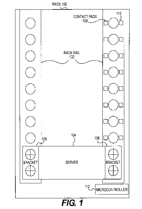
[0013] Figure 1 depicts a rack with two smart rails storing a server in
accordance with methods and systems consistent with the present invention.
[0014] Figure 2 illustrates a smart rack rail and a smart bracket.
[0015] Figure 3 illustrates a diagram of a smart bracket in accordance
with methods and system consistent with the present invention.
[0016] Figure 4 illustrates a circuit diagram of a smart rail having Id
pads, position pads and a microcontroller in accordance with methods and
system consistent with the present invention.
[0017] Figure 5 depicts steps of a method for adding new IT components
to a rack in accordance with methods and systems consistent with the present
invention.
[0018] Figure 6 depicts steps of a method for removing IT components
from a rack in accordance with methods and systems consistent with the
present invention.
[0019] Figure 7 depicts steps of a method for moving IT components in
a rack in accordance with methods and systems consistent with the present
invention.
DETAILED DESCRIPTION
[0020] Methods and systems in accordance with the present invention
provide the automatic tracking and management of the physical location of
information technology components in a data center. These methods and
systems automatically identify where a given IT component, such as a server,
router, switch or other device, is located. In particular, they automatically
identify which slot the IT component is located in a given rack in the data
center. When a server, for example, is added or removed from a particular
slot,
the tracking database is automatically notified and updated, and users of the
CA 02788805 2012-08-01
WO 2011/094012 PCT/US2011/000158
database have instantaneously accurate information about the location of each
IT component in a data center. If the server is changed to a different slot or
rack, the system immediately identifies that the given server or device is
located in a different location. Users can confidently rely on the information
in
the database when remotely managing the data center's IT assets. These
systems allow users to be sure that, when remotely managing a given server or
device, the physical location of the server or device will be known down to
the
slot level. For example, these systems may automatically update a database
with IT component data and timing of movements of IT components. This also
avoids the need for costly manual audits of IT components in a data center.
[0021] Most equipment used in today's data centers such as servers,
routers, UPS and rack managers are typically installed in racks or equipment
cabinets. Depending on their size and type, typical racks used in data centers
hold 1 to 48 separate IT components. Two brackets (one on each side of the
equipment) are used to mount the IT components in the racks.
[0022] Methods and systems in accordance with the present invention
identify which IT components are installed in each rack and in which slot the
IT component is installed. Insertion and removal of an asset is automatically
detected and communicated to the proper software layer responsible for asset
management. In one implementation, methods and systems in accordance with
the present invention include "smart" brackets containing small identification
("ID") chips that are attached to the rack-based IT components and a "smart"
rack rail. In one implementation, each smart bracket uniquely identifies the
IT
component to which it is attached. The smart rack rail identifies the slot of
the
rack in which the IT component resides and communicates with a
microcontroller to relay the position information to a database.
[0023] Figure 1 depicts a rack 100 with two smart rails 102 storing a
server 104 in accordance with methods and systems consistent with the present
invention. Although not shown on the figure, many other servers or other IT
components may be included in the slots on the rack or on other racks. In one
6
CA 02788805 2012-08-01
WO 2011/094012 PCT/US2011/000158
implementation, the system includes three primary components: smart brackets
106 including ID chips, smart rack rails 102 including contact pads for
interfacing with the ID chips on the smart bracket 106, and a microcontroller
112. Two spring-loaded contacts (shown on Figures 2 and 3) located on the
smart brackets 106 are mated to two contact pads 108, 110 mounted on the
smart rack rail 102 mounted on the rack 100. These contacts 108, 110 are used
to send ID information in the bracket 106 identifying the presence of IT
components (e.g., server 104), and to identify in which slots in the rack 100
the
particular bracket 106 is mounted on. The detection and collection of the rack
inventory is managed by the microcontroller 112 which interfaces with
management appliance products (from Avocent, Inc., for example) through a
network, such as a LAN, or a USB port. The equipment (e.g., brackets 106,
rails 102, contacts 108, 110, microcontroller 112, etc.) may be mounted
anywhere on the rack, slots or IT components, including the front or back. The
equipment may be mounted vertically down the side of the rack 100, thereby
reducing horizontal space consumed.
[0024] Figure 2 illustrates a smart rack rail 102 and a smart bracket 106.
As shown on the Figure, the smart bracket contacts 202, 204 mate with the
contacts 108, 110 on the rail 102. In one implementation, the smart brackets
106 stay attached to the IT component equipment once they are attached.
Appropriate security screws may be used to attach the smart bracket 106 to the
equipment. In addition to smart brackets 106, self-adhesive mounting modules
(ID chip and pads) may also be provided that attach to existing regular
brackets.
[0025] Figure 3 illustrates a diagram of a smart bracket 106 in
accordance with methods and system consistent with the present invention.
Each smart bracket 106 includes an ID chip 302 with a unique identification
value (e.g., a number) may be tagged (bar-coded) for viewing on front of each
bracket. Each ID chip 302 has an I/O pin (not shown) which is used to
determine location as described below. Two separate pads (ID pad 202,
7
CA 02788805 2012-08-01
WO 2011/094012 PCT/US2011/000158
position pad 204) on the smart bracket 106 are utilized to determine presence
and position of the installed IT components as described below. To determine
the presence of IT components, each smart bracket 106 has a passive ID chip
302 (for example, made by Maxim Integrated Products, Inc. (Maxim)) which
allows access, in one implementation, through Maxim's proprietary 1-Wire
interface. However, other types of ID chips 302 may be used. The Maxim
protocol is used to scan the wire for the presence of each of these chips.
Once
the inventory of the IT components is completed, a periodic scan may be done
to detect changes. The bracket will have the added ability (not shown) to
store
user information in a limited-sized persistent storage area.
[0026] Figure 4 illustrates a circuit diagram of a smart rail 102 having Id
pads 202, position pads 204 and a microcontroller 112 in accordance with
methods and system consistent with the present invention. When the system
scans to check installed or removed IT components, a quick scan keeps
inventory of IT components and issues alerts when a change occurs, such as an
addition, removal or move of an IT component. The quick scan may use the
Maxim protocol to scan for the present of the ID chips and hence the present
IT
components. The ID contact pads 202 are used to determine all of the IT
components on the rack 100. Once a change is discovered, a more thorough
and lengthy scan to detect position is initiated. To determine position of an
IT
component, each hole 402 or slot on the smart rack rail 102 has a position pad
108 and contact pad 110 and a transistor 406 and a capacitor 404. By varying
the value of each capacitor 404 on the rail 102, and predetermining
calibration
of the values, a correlation can be made between the unique capacitor value
and
the slot position. In one implementation, the unique value is the capacitor's
charge time. For example, a capacitor with a charge time of X milliseconds is
located at slot 1, a capacitor with a charge time of Y milliseconds is located
at
slot 2, etc.
[0027] During the position scan (deep scan), to determine the position of
an IT component, the microcontroller 112 individually turns on the I/O pin
(not
8
CA 02788805 2012-08-01
WO 2011/094012 PCT/US2011/000158
shown) of the ID chip 302 of the bracket 106 attached to that IT component.
By turning on the UO pin, the individual transistor 406 of the connected slot
drives the associated capacitor 404 to ground. This assures that only the
grounded capacitor 404 accepts the charge. The microcontroller 112 sends a
charge pulse to the capacitors 404 through a resistor and charging begins.
Then, the microcontroller 112 uses a voltage comparator (not shown) to detect
the present charging voltage, and the charge time is measured. The system
may determine that it took a certain amount of time to charge the capacitor
404,
so it determines that the bracket 106 and IT component are in the slot that
corresponds to that individual capacitor 404. Any of the brackets 106 may be
tested in this manner. In one implementation, since each capacitor 404 has a
unique value, and only 1 of 48 devices needs to be detected, for, example,
there
is enough resolution available to determine to which IT component and slot the
capacitor 404 corresponds.
[00281 The microcontroller 112 manages scanning and communication
with management devices/appliances. In one implementation, the
microcontroller 112 may be a single chip mounted in any appropriate location
on the rack. It may connect to a database or software layer through USB 408
(which can also be used to extract power) or over a network such as a LAN
408. In one implementation, the microcontroller 112 connects to the database
through an intermediate software layer. This software layer may include data
center management software, such as DSView from Avocent, Inc, which may
allow access to various IT components and provide remote management and
remote configuration. The microcontroller 112 may be connected to the
DSView application through a network, or may be plugged into another
appliance (e.g., via the USB or serial port of an Avocent console server or
KVM system) which is connected to the DSView through the network. The
DSView may pass the information received from the microcontroller 112 to the
database or other application that manages the IT components of the data
center. The microcontroller 112 provides an interface, via USB and an IP
9
CA 02788805 2012-08-01
WO 2011/094012 PCT/US2011/000158
connection, enabling management appliances installed in the rack 100 or
higher-level software applications, such as AMIE (Avocent MergePoint
Infrastructure Explorer) or ALM (Asset Lifecycle Manager), to get access to
rack inventory and change alerts. Other implementations are possible.
[0029] Figure 5 depicts steps of an exemplary method for adding new IT
components to a rack 100 in accordance with methods and systems consistent
with the present invention. First, IT components for a data center arrive at a
staging area. The equipment is provisioned (by, for example, preparing the
equipment for operation by loading the operating system, applications,
configuration and IP administration), and the smart brackets 106 are attached
to
the IT components such as server 104 (step 502). Next, the smart bracket ID is
entered into the asset management database along with other pertinent
information such as the corresponding serial number of the IT component (step
504). Then, the IT component is installed in the appropriate rack 100 and slot
(step 506).
[0030] The microcontroller 112 in the instrumented rack 100 detects the
addition of a new piece of equipment (during the quick scan process) (step
508). The microcontroller 112 performs a position scan of the rack 100),
collects the ID of the smart bracket 106 attached to the new piece of
equipment
and calculates the position (slot numbers) of the IT components within the
rack
100 using the capacitor detection process discussed previously (step 510). The
position and presence information is stored in the microcontroller 112 (step
512). The microcontroller 112 sends an alert to the systems management
software that the configuration of the rack 100 has changed (step 514). The
systems management software connects to the microcontroller 112 and
retrieves the information to update the database (step 516).
[0031] Figure 6 depicts steps of an exemplary method for removing IT
components from a rack 100 in accordance with methods and systems
consistent with the present invention. First, an IT component is removed from
the rack 100 (step 602). The microcontroller 112 in the instrumented rack 100
CA 02788805 2012-08-01
WO 2011/094012 PCT/US2011/000158
detects the removal of the equipment (in a quick scan) (step 604). The
information is updated in the microcontroller 112 (step 606). The
microcontroller 112 sends an alert to the systems management software that the
configuration of the rack 100 has changed (step 608). The systems
management software connects to the microcontroller 112 and retrieves the
information (step 610) to update the database.
[0032] Figure 7 depicts steps of a method for moving IT components in
a rack 100 in accordance with methods and systems consistent with the present
invention. First, an IT component is removed from a rack 100 (step 702). The
microcontroller 112 in the instrumented rack 100 detects the removal of the
equipment (during a quick scan) (step 704). The information is updated in the
microcontroller 112 (step 706). The microcontroller 112 sends an alert to the
systems management software that the configuration of the rack 100 has
changed (step 708). The SMS connects to the microcontroller 112 and
retrieves the information (step 710).
[0033] The IT component is then installed in a new slot location in the
rack 100 (step 712). The microcontroller 112 in the instrumented rack 100
detects the addition of a newly located IT component (during a quick scan)
(step 714). The microcontroller 112 then does a position scan of the rack 100,
collects the ID of the smart bracket 106 attached to the new IT component and
calculates the position (slot numbers) of the equipment within the rack 100
(step 716). The information is stored in the microcontroller 112 (step 718).
The microcontroller 112 sends an alert to the systems management software
that the configuration of the rack 100 has changed (step 720). The systems
management software connects to the microcontroller 112 and retrieves the
information (step 722) to update the database.
[0034] The foregoing description of various embodiments provides
illustration and description, but is not intended to be exhaustive or to limit
the
invention to the precise form disclosed. Modifications and variations are
possible in light of the above teachings or may be acquired from practice in
11
CA 02788805 2012-08-01
WO 2011/094012 PCT/US2011/000158
accordance with the present invention. It is to be understood that the
invention
is intended to cover various modifications and equivalent arrangements
included within the spirit and scope of the appended claims.
12