Sélection de la langue

Search

Sommaire du brevet 2788908 

Énoncé de désistement de responsabilité concernant l'information provenant de tiers

Une partie des informations de ce site Web a été fournie par des sources externes. Le gouvernement du Canada n'assume aucune responsabilité concernant la précision, l'actualité ou la fiabilité des informations fournies par les sources externes. Les utilisateurs qui désirent employer cette information devraient consulter directement la source des informations. Le contenu fourni par les sources externes n'est pas assujetti aux exigences sur les langues officielles, la protection des renseignements personnels et l'accessibilité.

Disponibilité de l'Abrégé et des Revendications

L'apparition de différences dans le texte et l'image des Revendications et de l'Abrégé dépend du moment auquel le document est publié. Les textes des Revendications et de l'Abrégé sont affichés :

  • lorsque la demande peut être examinée par le public;
  • lorsque le brevet est émis (délivrance).
(12) Brevet: (11) CA 2788908
(54) Titre français: ADAPTATEUR DE PLAQUE D'ACCES POUR UNE INSTALLATION ELECTRIQUE
(54) Titre anglais: ACCESS PLATE ADAPTER FOR ELECTRICAL FIXTURE
Statut: Accordé et délivré
Données bibliographiques
(51) Classification internationale des brevets (CIB):
  • H02G 3/14 (2006.01)
  • F21V 27/02 (2006.01)
  • H05K 5/03 (2006.01)
(72) Inventeurs :
  • MACINTOSH, W. KENNETH (Etats-Unis d'Amérique)
(73) Titulaires :
  • HUBBELL LIGHTING, INC.
(71) Demandeurs :
  • HUBBELL LIGHTING, INC. (Etats-Unis d'Amérique)
(74) Agent: FINLAYSON & SINGLEHURST
(74) Co-agent:
(45) Délivré: 2020-06-02
(22) Date de dépôt: 2012-09-07
(41) Mise à la disponibilité du public: 2013-04-25
Requête d'examen: 2017-08-11
Licence disponible: S.O.
Cédé au domaine public: S.O.
(25) Langue des documents déposés: Anglais

Traité de coopération en matière de brevets (PCT): Non

(30) Données de priorité de la demande:
Numéro de la demande Pays / territoire Date
13/280,638 (Etats-Unis d'Amérique) 2011-10-25

Abrégés

Abrégé français

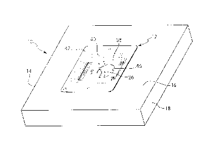
Un ensemble électrique, comme un ensemble déclairage, comprend un boîtier conçu pour être fixé au mur ou au plafond. Le boîtier comprend une paroi extérieure pour la fixation au mur ou au plafond et une ouverture pour les liaisons par fils entre le boîtier et la source dalimentation. Un adaptateur de plaque daccès est raccordé de manière amovible à louverture dans le boîtier pour définir un canal entre le boîtier et le mur ou le plafond. Ladaptateur comporte une paroi inférieure et une paroi latérale formant un puits et une paroi supérieure qui sétend vers lextérieur à partir dune extrémité supérieure de la paroi latérale. La paroi inférieure comprend plusieurs languettes formant des crochets pour le raccord à louverture dans la paroi du boîtier. La paroi supérieure de ladaptateur comprend une dimension pour entrer en contact avec la surface du mur ou du plafond pour former un joint détanchéité pour définir un canal fermé entre le boîtier et le mur ou le plafond.


Abrégé anglais

An electrical assembly, such as a lighting assembly, includes a housing adapted for mounting to a wall or ceiling. The housing has an outer wall for attaching to the wall or ceiling and an opening for wire connections between the housing and the power source. An access plate adapter is removably coupled to the opening in the housing to define a channel between the housing and the wall or ceiling. The adapter has a bottom wall and a side wall forming a well and an outwardly extending top wall at a top end of the side wall. The bottom wall has as plurality of tabs forming hooks for coupling with the opening in the housing wall. The top wall of the adapter has a dimension to contact the surface of the wall or ceiling and form a seal to define a closed channel between the housing and the wall or ceiling.

Revendications

Note : Les revendications sont présentées dans la langue officielle dans laquelle elles ont été soumises.


- 16 -
What is claimed is:
1. An access plate adapter for closing an access opening in an electrical
housing,
said adapter comprising:
a body having a substantially planar bottom wall and a side wall to define a
well, said side wall having a first end integrally formed with said bottom
wall, said
bottom wall having a coupling member projecting outwardly from said bottom
wall
for coupling said adapter to an access opening of the electrical housing, and
an
access opening to enable the passage of wires between said well and the
electrical
housing, said coupling member comprising a first tab having a hook shape for
engaging said electrical housing; and
an end wall extending outwardly from a second end of said side wall, said end
wall surrounding said well and forming a substantially planar surface for
forming a
seal with an outer surface of a wall or ceiling surface.
2. The access plate adapter of claim 1, wherein said first tab is formed at
a first
end on an outer surface of said bottom wall and extends in a first direction,
and said
coupling member has a second tab formed at a second end on the outer surface
of
said bottom wall and extending in a second direction, said first and second
tabs
being adapted for coupling with inner edges of the access opening of the
electrical
housing.

- 17 -
3. The access plate adapter of claim 1, wherein said access opening
includes a
knock-out.
4. The access plate adapter of claim 1, further comprising: a threaded hole
in
said bottom wall adapted for receiving a ground screw.
5. The access plate adapter of claim 4, further comprising: a pair of
dimples
extending from said bottom wall on opposite sides of said threaded hole and
adapted for contacting a washer associated with said ground screw.
6. The access plate adapter of claim 2, wherein said first tab has a length
greater
than a length of said second tab to allow said tabs to slide into engagement
with said
access opening in said electrical housing.
7. The access plate adapter of claim 6, wherein said first tab has a first
portion
extending parallel to said bottom with a first end coupled to said bottom wall
and a
second distal end, said first portion being spaced from said bottom wall, and
a
second portion coupled to said second distal end of said bottom wall and being
spaced from said first portion a distance greater than said first distance.
8. A method of mounting an electrical housing to a wall or ceiling, said
method
comprising the steps of:
coupling an access plate to an outer wall of the electrical housing, the outer
wall of the housing having an opening adapted for receiving electrical wires,
said
access plate having a first open end coupled to said electrical housing by a
coupling

- 18 -
member to close said opening in said electrical housing and a second open end
defining a channel between said first end and second end, said coupling member
having a first tab inserted into said opening in said electrical housing; and
coupling said electrical housing to said wall or ceiling where said second end
of said access plate is in contact with an outer surface of said wall or
ceiling to form a
sealed continuous channel between said outer surface of said wall or ceiling
and said
outer wall of said electrical housing.
9. The method of claim 8, wherein said electrical housing is spaced from
said wall
or ceiling, and said access plate has a side wall, a bottom wall at said first
end and a
top wall at said second end, said access plate extending between said outer
wall of
said electrical housing and the outer surface of said wall or ceiling.
10. The method of claim 9, wherein said first tab is at a first end of said
bottom
wall forming a first coupling hook, and a second tab at a second end of said
bottom
wall forming a second coupling hook, said method comprising: inserting said
first and
second hooks into said opening in said electrical housing to couple said
adapted to
said electrical housing.
11. The method of claim 9, wherein said bottom wall of said access plate
has a
threaded hole and a pair of dimples on opposite sides of said threaded hole,
said
method comprising: threading a ground screw having a ground wire connected
thereto into said threaded hole to make grounding contact with said access
plate.

- 19 -
12. The access plate adapter of claim 1, wherein said first tab engages an
edge of
an opening in said electrical housing.
13. The access plate adapter of claim 1, wherein said coupling member
further
comprises a second tab having a hook shape for engaging an edge of an opening
in
said electrical housing, said second tab extending in a direction opposite
said first
tab.
14. The electrical assembly of claim 1, wherein said access plate has a
bottom wall
with a coupling member, said coupling member comprising a first tab having a
shape
for engaging an edge of an opening in said housing.
15. The electrical assembly of claim 14, wherein said coupling member
further
comprises a second tab having a hook shape for engaging an edge of an opening
in
said housing and said second tab extending in a direction opposite said first
tab.
16. An access plate adapter for closing an access opening in an electrical
housing,
said adapter comprising: a body having a substantially planar bottom wall and
a side
wall to define a well, said side wall having a first end integrally formed
with said
bottom wall, said bottom wall having a coupling member projecting outwardly
from
said bottom wall for coupling said adapter to an access opening of the
electrical
housing, and an access opening including a knock-out to enable the passage of
wires
between said well and the electrical housing; and an end wall extending
outwardly

- 20 -
from a second end of said side wall, said end wall surrounding said well and
forming
a substantially planar surface for forming a seal with an outer surface of a
wall or
ceiling surface.
17. The access plate adapter of claim 16, wherein said coupling member
comprises: a first tab formed at a first end on an outer surface of said
bottom wall
and extending in a first direction, and a second tab formed at a second end on
the
outer surface of said bottom wall and extending in a second direction, said
first and
second tabs being adapted for coupling with inner edges of the access opening
of the
electrical housing.
18. The access plate adapter of claim 16, further comprising: a threaded
hole in
said bottom wall adapted for receiving a ground screw.
19. The access plate adapter of claim 18, further comprising: a pair of
dimples
extending from said bottom wall on opposite sides of said threaded hole and
adapted for contacting a washer associated with said ground screw.
20. The access plate adapter of claim 17, wherein said first tab has a
length
greater than a length of said second tab to allow said tabs to slide into
engagement
with said access opening in said electrical housing.
21. The access plate adapter of claim 20, wherein said first tab has a
first portion
extending parallel to said bottom with a first end coupled to said bottom wall
and a
second distal end, said first portion being spaced from said bottom wall, and
a

- 21 -
second portion coupled to said second distal end of said bottom wall and being
spaced from said first portion a distance greater than said first distance.
22. An electrical assembly comprising:
a housing enclosing an electrical device and having a housing wall adapted for
mounting to a wall or ceiling, said housing wall having an opening adapted for
electrical wiring to pass through; and
an access plate having a first end including a first coupling member formed on
an outer surface of said first end and extending in a first direction and a
second
coupling member formed on the outer surface of said first end and extending in
a
second direction for coupling said access plate to said housing wall, and a
second end
adapted for contacting an outer surface of the wall or ceiling and defining a
channel
between said opening in said housing wall and the wall or ceiling for
enclosing the
wiring passing between said housing wall and the wall or ceiling, said access
plate
having a dimension to space said housing from the wall or ceiling and close a
gap
between said housing and the wall or ceiling.
23. The electrical assembly of claim 22, wherein said housing includes a
mounting
member for coupling said housing to said wall or ceiling, said housing and
said access
plate second end forming a seal with said wall or ceiling, said access plate
extending
between said housing and said wall or ceiling.
24. The electrical assembly of claim 22, wherein said access plate
comprises: a
body having a side wall with an opening at said first end and an opening at
said
second end, said side wall defining said channel.

- 22 -
25. The electrical assembly of claim 24, wherein said access plate further
comprises: a bottom wall haying an opening therein with a dimension to allow
wiring
to pass through, and where said side wall extends upwardly from said bottom
wall to
form a well.
26. The electrical assembly of claim 25, wherein said access plate further
comprises: an end wall at said second end substantially parallel to said
bottom wall
for contacting said wall or ceiling.
27. The electrical assembly of claim 26, wherein said end wall extends
outwardly
from said side wall and surrounds said opening formed by said side wall.
28. The electrical assembly of claim 25, wherein said first coupling member
extends outwardly from said bottom wall.
29. The electrical assembly of claim 28, wherein said first coupling member
includes a first coupling tab at a first end of said bottom wall to define a
first hook
having a first length, and said second coupling member includes a second
coupling
tab at a second end of said bottom wall to define a second hook extending in a
direction opposite to said first hook and having a second length greater than
said
first length, said first and second hooks being adapted for coupling with
opposite
edges of said opening in said wall of said housing.
30. The electrical assembly of claim 29 wherein said second coupling tab
has
opposite corners with an upturned detent.

- 23 -
31. The electrical assembly of claim 29 wherein said second coupling tab is
cut
from said bottom wall to define an opening and where said opening has opposite
corners with a downwardly projecting detent.
32. The electrical assembly of claim 25, wherein said bottom wall includes
a
knock-out to form an opening in said bottom wall, a threaded hole adapted for
receiving a ground screw, and a pair of dimples on opposite sides of said
screw hole
adapted for contacting a washer on said ground screw.
33. The electrical assembly of claim 22, wherein said first coupling member
comprising a first tab having a shape for engaging an edge of an opening in
said
housing.
34. The electrical assembly of claim 33, wherein said second coupling
member
further comprises a second tab having a hook shape for engaging an edge of an
opening in said housing and said second tab extending in a direction opposite
said
first tab.
35. A method of mounting an electrical housing to a wall or ceiling, said
method
comprising the steps of:
coupling an access plate having a side wall, a bottom wall at said first end
and
a top wall at said second end to an outer wall of an electrical housing, the
bottom
wall including a first tab at a first end forming a first coupling hook and a
second tab
at a second end of said bottom wall forming a second coupling hook, the outer
wall
of the housing having an opening adapted for receiving electrical wires, said
access

- 24 -
plate having a first open end coupled to said electrical housing to close said
opening
in said electrical housing and a second open end defining a channel between
said
first end and second end; and
coupling said electrical housing to said wall or ceiling where said second end
of said access plate is in contact with an outer surface of said wall or
ceiling to form a
sealed continuous channel between said outer surface of said wall or ceiling
and said
outer wall of said electrical housing.
36. The method of claim 35, wherein said electrical housing is spaced from
said
wall or ceiling, and said access plate extends between said outer wall of said
electrical housing and the outer surface of said wall or ceiling.
37. The method of claim 35, wherein said bottom wall of said access plate
has a
threaded hole and a pair of dimples on opposite sides of said threaded hole,
said
method comprising: threading a ground screw having a ground wire connected
thereto into said threaded hole to make grounding contact with said access
plate.

Description

Note : Les descriptions sont présentées dans la langue officielle dans laquelle elles ont été soumises.


- 1 -
ACCESS PLATE ADAPTER FOR ELECTRICAL FIXTURE
Field of the Invention
[0001] The present invention is directed to an electrical assembly such
as a lighting assembly or fixture and an access plate adapter that can
contact the surface of a wall or ceiling. The invention is particularly
directed to an access plate adapter for closing the access opening in the
electrical assembly and forming an electrical seal with the wall or ceiling
to carry electrical wiring between the electrical assembly and the space
above the ceiling or behind the wall.
Background of the Invention
[0002] Electrical assemblies such as lighting fixtures generally have an
access opening in the housing to feed wiring to the power source or to an
electrical juncture box. The housing can have a cable connector coupled
to the opening in the housing to clamp the electrical cable to the
housing.
CA 2788908 2019-09-30

CA 02788908 2012-09-07
- 2 -
[0003] Various cover plates are provided with the electrical assembly
that can be removed from the housing to make the necessary electrical
connections during installation. The cover plates are generally flat or
shaped to conform to the housing and can be attached to the housing by
hooks, tabs, fasteners, or a combination thereof.
[0004] Many electrical devices and assemblies are known in the art
that have removable cover plates and access plates. For example, U.S.
Patent No. 3,356,840 to Cohen discloses a light fixture mounting
assembly having a ring with a flange that engages the top surface of the
ceiling and a cylindrical side wall that extends through the opening in
the ceiling. A U-shaped yoke member is attached to the ring by hooking
onto the edges of the ring.
[0005] U.S. Patent No. 7,683,257 to Shotey et al. discloses an electrical
cover plate having a frame with an adapter plate recessed in the frame.
The adapter plate couples with the frame and has a size to fill the recess.
[0006] U.S. Patent No. 7,494,371 to Kidman discloses a face plate for
connecting to an electrical box. The electrical box includes an anchor
that is removably attached thereto for supporting the electrical wiring
device. The cover is snapped to the anchor by projections that extend
through an opening in the anchor.
[0007] U.S. Patent No. 7,437,580 to Blackman et al. discloses an
adapter device for mounting a ceiling light fixture. The adapter is a
plate-like member having bendable tabs that extend through the opening
in the ceiling where the tabs are bent to grip the ceiling. The adapter
includes legs for temporarily supporting the light fixture while being
connected to the electrical box.

CA 02788908 2012-09-07
- 3 -
[0008] U.S. Patent Publication No. 2011/0116276 to Okamura et al.
discloses a mounting assisting adapter member for a lighting apparatus.
The adapter includes a ring with a recessed portion that fits within the
opening in the ceiling. The lighting assembly is hooked to the rim by
spring tabs. The ring is secured to the ceiling by top flanges that are
folded over onto the inner surface of the ceiling.
[0009] U.S.
Patent Publication No. 2006/0101741 to Rae discloses
a recessed lighting fixture adapter for mounting a recessed light in a
ceiling or wall. The adapter includes an inner plate and an outer plate
and engages opposite surfaces of the ceiling. The inner and outer plate
are connected together by screws which draw the plates together to
clamp to the ceiling. The inner and outer plates have an opening to
receive the recessed lighting fixture.
[0010] U.S. Patent No. 7,048,575 to Kidman discloses a mounting
assembly for a low voltage terminal. The assembly includes a base that
fits into the opening in the wall and receives a body for supporting the
low voltage terminal. A cover plate is attached to the body by screws.
[0011] While these devices are suitable for their intended use, there is
a continuing need in the industry for improved mounting assemblies and
access cover plates.
Summary of the Invention
[0012] The present invention is directed to an electrical assembly and
to an access plate that is removably coupled to the electrical assembly.
In particular, the invention is directed to an electrical assembly having
an access plate that extends between the electrical assembly and a wall
or ceiling surface.

CA 02788908 2012-09-07
- 4 -
[0013] The electrical assembly of the invention can be a lighting
assembly or fixture that can be mounted to a wall or ceiling using
various fasteners, mounting brackets, hangers, and the like. The
housing includes an access opening or a knockout that can be removed
to form an access opening. The access opening in the housing includes a
removable access plate.
[0014] Accordingly, one aspect of the invention is to provide an
electrical assembly with a removable access plate that is coupled to the
housing of the electrical assembly and that is able to contact the surface
of the wall or ceiling. The access plate of the invention is particularly
suitable for use where the electrical assembly is spaced from the
mounting surface so that the access plate closes the gap between the
access opening in the electrical assembly and the opening in the
mounting surface.
[0015] Another feature of the invention is to provide a removable
access plate for coupling with a housing and which defines a wiring
channel between the housing and the wall or ceiling.
[0016] A further feature of the invention is to provide an access plate
adapter for use with an electrical assembly that forms a seal with the
surface of the wall or ceiling.
[0017] Still another feature of the invention is to provide an access
plate adapter that can be coupled to the access opening of an electrical
assembly and has a height to extend between the electrical assembly and
the wall or ceiling to prevent having exposed wires between the electrical
assembly and the surface of the wall or ceiling.
[0018] The electrical assembly of the invention generally includes a
housing with an outer wall having an access opening for electrical wiring.

CA 02788908 2012-09-07
- 5 -
In one embodiment of the invention, the electrical assembly is a lighting
fixture such as a surface mount trouffer having a housing with an open
bottom side and one or more lamps or other light source for directing
light through the open bottom. The housing can have one or more side
walls and a top end wall. The top end wall can be mounted to the ceiling
or wall directly or by means of a mounting bracket or fastener. Where
the top end wall of the housing is spaced from the wall or ceiling, an
access plate adapter is used to form a closed channel between the
housing and the electrical junction box or between the opening in the
wall or ceiling and the access opening in the housing.
[0019] The access plate is an adapter having a dimension to close the
access opening of the housing of the electrical assembly and has a height
to extend between the housing and the surface of the wall or ceiling. The
access plate adapter can have a height of about 1/2 inch thick to about 1
inch although the height can vary depending on the intended use.
[0020] In one embodiment of the invention, the access plate adapter
has a bottom wall adapted for coupling to the access opening of the
housing of the electrical assembly. The access plate is formed with a
drawn portion to form a side wall and a well with an open side opposite
the bottom wall. Preferably, the side wall is continuous and has a height
to extend away from the top end wall of the housing when the bottom
wall is coupled to the housing. An end wall of the adapter extends
outwardly from a top end of the side wall and extends around the
periphery of the side wall. The end wall preferably has a dimension to
form an electrical seal with the wall or housing to close the gap between
the electrical assembly and the wall or ceiling.

CA 02788908 2012-09-07
-6-
100211 These and other aspects of the invention are basically attained
by providing an access plate adapter for closing an opening in an
electrical housing. The adapter comprises a body having a substantially
planar bottom wall and a side wall to define a well. The side wall has a
first end integrally formed with the bottom wall. The bottom wall has a
coupling member for coupling the adapter to an access opening of the
electrical housing, and an access port to enable the passage of wires
between the well and the electrical housing. An end wall extends
outwardly from a second end of the side wall. The end wall surrounds
the well and forms a substantially planar surface for forming a seal with
a wall or ceiling surface.
[0022] The various features of the invention are also attained by
providing an electrical assembly comprising a housing receiving an
electrical device and having a wall adapted for mounting against a wall or
ceiling. The housing wall has an opening adapted for electrical wiring to
pass through. An access plate has a first end coupled to the wall of the
housing and a second end adapted for contacting the wall or ceiling and
defining a channel between the opening in the wall of the housing and
the wall or ceiling for enclosing the wiring passing between the wall of the
housing and the wall or ceiling.
[0023] The features of the invention are further attained by providing a
method of mounting an electrical housing to a wall or ceiling. The
method comprises the step of coupling an access plate to an opening in a
wall of the electrical housing. The wall of the housing has an opening
adapted for passing electrical wires between the housing and a power
source. The access plate has a first open end coupled to the electrical
housing to close the opening in the electrical housing and a second open

- 7 -
end defining a channel between the first end and the second end. The
electrical housing is coupled to the wall or ceiling where the second
end of the access plate is in contact with the wall or ceiling to form
a sealed continuous channel between the wall or ceiling and the
electrical housing.
[0023A] In a broad aspect, the present invention pertains to an access
plate adapter for closing an access opening in an electrical housing,
the adapter comprising a body having a substantially planar bottom
wall and a side wall to define a well. The side wall has a first end
integrally formed with the bottom wall, the bottom wall having a
coupling member projecting outwardly from the bottom wall for coupling
the adapter to an access opening of the electrical housing. There is
an access opening to enable the passage of wires between the well and
the electrical housing, the coupling member comprising a first tab
having a hook shape for engaging the electrical housing. An end wall
extends outwardly from a second end of the side wall, and the end wall
surrounds the wall and forms a substantially planar surface or forming
a seal with an outer surface of a wall or ceiling surface.
[0023B] In a further aspect, the present invention embodies a method
of mounting an electrical housing to a wall or ceiling. The method
comprises coupling an access plate to an outer wall of the electrical
housing, the outer wall of the housing having an opening adapted for
receiving electrical wires. The access plate has a first open end
coupled to the electrical housing by a coupling member to close the
opening in the electrical housing, and a second open end defining a
channel between the first end and the second end. The coupling member
has a first tab inserted into the opening in the electrical housing,
and couples the electrical housing to the wall or ceiling where the
second end of the access plate is in contact with an outer surface of
the wall or ceiling, forming a sealed continuous channel between the
CA 2788908 2019-09-30

- 7a -
outer surface of the wall or ceiling and the outer wall of the
electrical housing.
[0023C] In a still further aspect, the present invention provides an
access plate adapter for closing an access opening in an electrical
housing, the adapter comprising a body having a substantially planar
bottom wall and a side wall to define a well. The side wall has a
first end integrally formed with the bottom wall, and the bottom wall
has a coupling member projecting outwardly from the bottom wall for
coupling the adapter to an access opening of the electrical housing.
An access opening includes a knock-out to enable the passage of wares
between the well and the electrical housing, and an end wall extends
outwardly from a second end of the side wall. The end wall surrounds
the well and forms a substantially planar surface for forming a seal
with an outer surface of a wall or ceiling surface.
[0023D] In a further aspect, the present invention provides an
electrical assembly comprising a housing enclosing an electrical
device and having a housing wall adapted for mounting to a wall or
ceiling. The housing wall has an opening adapted for electrical
wiring to pass through. There is provided an access plate having a
first end including a first coupling member formed on an outer surface
of the first end and extending in a first direction and a second
coupling member formed on the outer surface of the first end and
extending in a second direction, for coupling the access plate to the
housing wall. A second end is adapted for contacting an outer surface
of the wall or ceiling and defines a channel between the opening in
the housing wall and the wall or ceiling. The access plate has a
dimension to space the housing from the wall or ceiling and close a
gap between the housing and the wall or ceiling.
CA 2788908 2019-09-30

- 7b
[0023E] In a yet further aspect, the present invention sets forth a
method of mounting an electrical housing to a wall or ceiling. The
method comprises coupling an access plate having a side wall, a bottom
wall at the first end and a top wall at the second end to an outer
wall of an electrical housing. The bottom wall includes a first tab
at a first end forming a first coupling hook, and a second tab at a
second end of the bottom wall forming a second coupling hook. The
outer wall of the housing has an opening adapted for receiving
electrical wires, and the access plate has a first open end coupled to
the electrical housing to close the opening in the electrical housing
and a second open end defines a channel between the first end and the
second end. The electrical housing is coupled to the wall or ceiling
where the second end of the access plate is in contact with an outer
surface of the wall or ceiling, to form a sealed continuous channel
between the outer surface of the wall or ceiling and the outer wall of
the electrical housing.
[0024] These and other aspects, advantages and salient features of
the invention will become apparent from the following detailed
description of the inventionwhich, in conjunction with the annexed
drawings, disclose various embodiments of the invention.
CA 2788908 2019-09-30

- 7c -
Brief Description of the Drawings
[0025] The following is a brief description of the drawings, in
which:
[0026] Figure 1 is a perspective view of the electrical assembly and
access plate in one embodiment of the invention;
[0027] Figure 2 is a partial cross-sectional view of the lighting
assembly mounted to a ceiling and electrical box in the ceiling in a
first embodiment of the invention;
[0028] Figure 3 is a partial cross-sectional view of the lighting
assembly having a cable clamp for the wires in a second embodiment of
the invention;
[0029] Figure 4 is a top perspective view of the access plate adapter
in one embodiment of the invention;
[0030] Figure 5 is a top view of the access plate of Figure 4;
[0031] Figure 6 is a side view of the access plate of Figure 5;
[0032] Figure 7 is an end view of the access plate as seen from the
left side of Figure 5;
CA 2788908 2019-09-30

CA 02788908 2012-09-07
- 8 -
[0033] Figure 8 is a cross-sectional view of the access plate taken along
line 8-8 of Figure 5;
[0034] Figure 9 is a cross-sectional view of the access plate taken along
line 9-9 of Figure 5 showing the mounting tab;
[0035] Figure 10 is a cross-sectional view of the access plate taken
along line 10-10 of Figure 5 showing the ground screw mounting hole;
[0036] Figure 11 is a cross-sectional view of the access plate taken
along line 11-11 of Figure 5 showing one of the coupling tabs;
[0037] Figure 12 is a cross-sectional view of the access plate and
housing of the electrical assembly showing the access plate sliding into
the access opening;
[0038] Figure 13 is a cross-sectional view of the access plate and the
housing of the electrical assembly showing the access plate coupled to
the housing;
[0039] Figure 14 is a top view of the adapter plate in a second
embodiment of the invention; and
[0040] Figure 15 is a cross sectional view of the adapter plate taken
along line 15-15 of Figure 14.
Detailed Description of the Invention
[0041] The present invention is directed to an electrical assembly
having a housing with an access opening and an access plate coupled to
the housing to close the opening. The invention is particularly directed
to an access plate adapter that can be coupled to the access opening in
the housing and that has a height to extend between the housing and the
wall or ceiling surface.

CA 02788908 2012-09-07
- 9 -
[0042] Referring to the drawings, the invention is directed to an
electrical assembly such as a lighting assembly 10 and an access plate
12. In the embodiment illustrated, the electrical assembly is a lighting
assembly that can be recessed or surface mounted. In alternative
embodiments, the electrical assembly can be any number of known
electrical devices such as emergency lights, signs, motion detectors or
other electrical components. The lighting assembly can be a surface
mounted trouffer fixture.
[0043] The lighting assembly 10 includes a housing 14 having a top
wall 16 and side walls 18. An open bottom side 19 can have various
lenses or shades as known in the art to direct light in a downward
.direction. The housing 14 includes a ballast 20 shown in Figure 2 that is
connected to the lamps. For simplicity, the lamps are not shown in
Figure 2 although it will be understood that various arrangements of
lamps, reflector lens, shades and other components can be used as in
conventional lighting assemblies. In one example, the lamps can be one
or more fluorescent lamps connected to a respective lamp base that is
mounted in the housing.
[0044] The housing 14 can be attached to a wall or ceiling surface
using various brackets and fasteners. In one embodiment, the housing
is a surface mount trouffer fixture. As shown in Figure 2, the housing 14
is attached to a ceiling 22 by fasteners 24 passing through the top wall
16 of the housing. Other means of mounting the lighting assembly to the
ceiling can be used such as brackets as known in the art. The ballast 20
is connected to the power source by wires 26 extending from an electrical
junction box 28. In the embodiment shown in Figure 2, the electrical
box 28 is mounted within the opening 30 of the ceiling 22 or directly

CA 02788908 2012-09-07
- 10 -
above the opening in the ceiling. The wires are fed directly from the
electrical box 28 through the opening in the access plate 12 to the ballast
20. In an alternative embodiment shown in Figure 3, a cable clamp 32 is
coupled to the access plate 12 to supply the wires from the power source
to the ballast 20.
[0045] The top wall 16 of housing 14 has an access opening in the
housing 14 for supplying electrical wiring into the housing. The access
plate 12 of the invention is coupled to the top wall 16 to close the access
opening 34 while allowing the wiring to pass through.
[0046] Referring to Figure 4, the access plate 12 has a length and
width sufficient to close the access opening 34 in the housing 14. The
access plate 12 has a body with a bottom wall 38 and a side wall 40, and
a top or end wall 42. Bottom wall 38 has a substantially rectangular
configuration in the embodiment shown corresponding to the shape and
dimension of the access opening 34 in the top wall 16 of housing 14.
The bottom wall 38 includes a knock-out 44 or pry-out plug that can be
removed to form an opening 46. The opening 46 defines a passage for
wires to pass directly from the electrical box 28 as shown in the
embodiment of Figure 2.
[0047] The access plate is preferably made of steel that is cut and
stamped to the desired shade and dimensions. The steel is preferably
0.048 thick or more. The opening 46 in one preferred embodiment has a
diameter of about 1.5 inches.
[0048] In alternative embodiments, an optional cable clamp 32 can be
coupled to the access plate 12 as shown in Figure 3. The cable clamp 32
typically has a threaded end 48 that is inserted through the opening 46.
A lock nut 50 is threaded onto the threaded end to secure the cable

CA 02788908 2012-09-07
- 1 1 -
clamp to the access plate for carrying wiring to the ballast or other
electrical components within the housing 14. A clamp is provided to
clamp to the cable and provide strain relief for the cable.
[0049] Bottom wall 38 is provided with coupling members for coupling
the access plate 12 to the opening in the housing 14. In the embodiment
shown, the coupling members include first tabs 52 formed at a first end
54 of the bottom wall 38. The tabs are cut or punched from the bottom
wall to define an opening 56. The tabs 52 as shown in Figures 6 and 8
project outwardly with respect to the access plate toward the side wall
40. The tabs 52 extend from the bottom surface 58 a distance to form a
hook-shaped coupling member for engaging the edge of the opening 46 in
the wall 16 of the housing 14. The bottom wall 38 also includes a second
coupling tab 60 at a second end 62 of bottom wall 38. The second tab 60
is cut or punched from the bottom wall to form an opening 64 so that the
tab 60 extends downwardly and outwardly with respect to the bottom
wall 38 and a width slightly less than the width of the access opening.
[0050] As shown in Figures 6, 7 and 8, the second tab 60 extends
outwardly in a generally parallel plane with respect to the plane of the
bottom wall 38 and has a length greater than the length of the first tabs
54. The second tab 60 has a width extending substantially the width of
the bottom wall 38. As shown in Figures 7 and 8, the second tab 60
includes a first portion 66 coupled to the bottom wall 38 and a second
portion 68 extending from the first portion 66. As shown in Figure 8, the
second portion is bent outwardly a distance greater than the distance of
the first portion 66. The ends of the second portion have an upwardly
bent corner 70 to form a projecting point. The first portion 66 includes a

CA 02788908 2012-09-07
- 12 -
centrally located detent 72 extending in an upward direction to
frictionally engage the edge of the access opening in the housing 14.
[0051] Bottom wall 38 also includes a ground connection 74. The
ground connection in the embodiment shown includes a collar 76 having
an axial bore 78 extending through the collar 76 and the bottom wall 38.
The axial bore can have internal threads for receiving a ground screw 80.
Alternatively, the ground screw 80 can be a self-tapping screw to cut
threads in the axial bore 78. A pair of downwardly extending dimples 82
are formed on opposite sides of the axial bore 78 as shown in Figure 10.
The dimples 82 provide a contact surface for engaging a washer 84 on
the ground screw 80.
[0052] The access plate 12 is preferably formed as a one piece unitary
unit that is cut and stamped to the shape shown in Figure 4. The side
wall 40 is drawn from a blank of sheet material and can have a height of
about 1/2 inch to about 1 inch. The side wall is preferably integrally
formed as a one piece unit with the bottom wall 38. The side wall 40 is
preferably continuous and extends around the peripheral edge of the
bottom wall 38. In the embodiment shown, the side wall 40 extends
upwardly from a top surface 86 of the bottom wall 38 at an incline.
Alternatively, side wall 40 can be substantially perpendicular to the
bottom wall 38.
[0053] The end wall 40 as shown in Figure 4 extends radially outward
from the side wall 40 and has a substantially flat planar configuration.
The end wall 42 preferably has a dimension to overlie the opening 30 in
the ceiling 22 as shown in Figures 2 and 3 or the wall or other support
surface. End wall 42 can have one or more apertures 88 to receive a

CA 02788908 2012-09-07
- 13 -
fastener for attaching the access plate 12 to the housing 14 or to the
ceiling 22.
[0054] The access plate 12 forms an adapter that is connected to the
housing of the electrical assembly to define a channel between the
housing and the wall or ceiling to guide wires to the electrical assembly.
The wires are passed through the opening 46 in the bottom wall 38 of the
access plate 12 for connecting the electrical assembly to the power
source as shown in Figures 1 and 2. The access plate is coupled to the
housing 14 by inserting the second tab 60 below the surface of the top
wall 16 of the housing until the edge of the opening contacts the edge
portion of the tab 60 as shown in Figure 12. The tabs 52 and 60 are
spaced apart a distance to enable the first tabs 52 to extend into the
opening 46 as shown in Figure 12. The access plate can then slide in the
direction of arrow 90 to engage the tabs 52 with the opposite edge of the
opening 46 as shown in Figure 13. The edges of the tabs 52 and 60
engage the edges of the opening 46 to grip the edges and retain the
access plate in position. The upturned corners 70 of the tab 60 engage
the surface of the housing wall so that the corner points frictionally
engage the surface of the housing wall to resist movement of the adapter
plate where the tab 60 is in the desired location.
[0055] The access plate adapter of the invention is particularly suitable
for forming a channel between the top surface of the housing 14 to the
bottom surface of the wall or ceiling 22 as shown in Figures 2 and 3.
The end wall 42 preferably forms a seal around the opening 30 so that
the wires and connectors passing between the electrical assembly 10 and
the space above the ceiling 22 are enclosed by the side wall 40. The
housing 14 is connected to the ceiling 22 in the embodiment shown by

CA 02788908 2012-09-07
- 14 -
fasteners 24 where the top surface of the housing 14 is spaced from the
face of the wall or ceiling. The gap formed between the wall or ceiling
and the housing are enclosed by the access plate adapted 12.
[0056] In a further embodiment shown in Figures 14 and 15 an
adapter plate 100 is shown. The adapter plate 100 is similar to the
adapter plate 12 with similar size and dimensions for coupling to the
access opening in the housing of the lighting assembly and mating with
the surface of the ceiling or wall. The adapter plate 100 in the
embodiment of Figures 14 and 15 includes a first coupling tab 102 at a
first end of a bottom wall 104 and a pair of second compiling tabs 106
and a second end of the bottom wall 104. As in the previous
embodiment, the coupling tabs 102 and 106 project in opposite
directions for coupling with the access opening in the lighting assembly.
[0057] The coupling tab 102 in the embodiment shown is cut from the
bottom wall 104 and bent to the shape and position shown in Figure 15.
The coupling tab 102 has a first leg 108 bent downwardly from the
bottom wall 104 in a direction substantially perpendicular to the plane of
the bottom wall 104. A second leg 110 extends from a distal end of the
first leg 108 to extend in a plane substantially parallel to the bottom wall
104. The second leg 110 is spaced from the bottom wall 104 a distance
corresponding to the thickness of the wall of the housing to couple with
the housing.
[0058] The second leg 110 as shown in Figure 14 has a substantially
flat, planar shape with a dimple 112 formed in a middle portion. The
dimple 112 extends toward the bottom wall 104 a distance to contact an
inner surface of the housing of the lighting assembly to assist in gripping
and frictionally engaging the housing of the lighting assembly.

CA 02788908 2012-09-07
- 15 -
[0059] Referring to Figure 14, the coupling tab 102 is cut from the
bottom wall 104 to form inwardly extending detents 114 at opposite
corners of the opening 116 formed by cutting tab 102 from the bottom
wall 104. The detents 114 are formed with perpendicular edges 118
extending inwardly from an end 120 of the opening 116 and sides 122 of
the opening 116. The edges of the detents converge to a point 124
projecting inwardly into the opening 116. As shown in Figure 15 the
detents 114 are bent downward from the plane of the bottom wall 104
toward the second leg 110 of the tab 102.
[0060] The adapter plate 100 is coupled to the housing of the lighting
assembly in a manner similar to the previous embodiment. The tab 102
is inserted into the opening in the housing so that the tab slides under
the top wall of the housing. The leg 106 then slides under the top wall at
the opposite end. The downwardly extending detents 114 and the
upwardly extending dimple 112 engage and frictionally contact the top
and bottom surfaces of the housing wall to hold the adapter plate in a
fixed position coupled to the housing.
[0061] While various embodiments have been chosen to illustrate the
invention, it will be understood by those skilled in the art that various
changes and modifications can be made without departing from the spirit
and scope of the invention as defined in the appended claims.

Dessin représentatif
Une figure unique qui représente un dessin illustrant l'invention.
États administratifs

2024-08-01 : Dans le cadre de la transition vers les Brevets de nouvelle génération (BNG), la base de données sur les brevets canadiens (BDBC) contient désormais un Historique d'événement plus détaillé, qui reproduit le Journal des événements de notre nouvelle solution interne.

Veuillez noter que les événements débutant par « Inactive : » se réfèrent à des événements qui ne sont plus utilisés dans notre nouvelle solution interne.

Pour une meilleure compréhension de l'état de la demande ou brevet qui figure sur cette page, la rubrique Mise en garde , et les descriptions de Brevet , Historique d'événement , Taxes périodiques et Historique des paiements devraient être consultées.

Historique d'événement

Description Date
Paiement d'une taxe pour le maintien en état jugé conforme 2022-09-16
Inactive : TME en retard traitée 2022-09-16
Inactive : Certificat d'inscription (Transfert) 2022-03-15
Inactive : Transferts multiples 2022-02-04
Représentant commun nommé 2020-11-07
Accordé par délivrance 2020-06-02
Inactive : Page couverture publiée 2020-06-01
Inactive : COVID 19 - Délai prolongé 2020-03-29
Préoctroi 2020-03-26
Inactive : Taxe finale reçue 2020-03-26
Un avis d'acceptation est envoyé 2019-12-17
Lettre envoyée 2019-12-17
Un avis d'acceptation est envoyé 2019-12-17
Inactive : Approuvée aux fins d'acceptation (AFA) 2019-11-06
Inactive : Q2 réussi 2019-11-06
Représentant commun nommé 2019-10-30
Modification reçue - modification volontaire 2019-09-30
Inactive : Dem. de l'examinateur par.30(2) Règles 2019-09-11
Inactive : Rapport - Aucun CQ 2019-09-05
Modification reçue - modification volontaire 2019-05-28
Inactive : Dem. de l'examinateur par.30(2) Règles 2019-01-10
Inactive : Rapport - CQ réussi 2019-01-08
Modification reçue - modification volontaire 2018-09-11
Inactive : Dem. de l'examinateur par.30(2) Règles 2018-03-19
Inactive : Rapport - Aucun CQ 2018-03-19
Inactive : CIB attribuée 2018-02-07
Inactive : CIB attribuée 2018-02-02
Lettre envoyée 2017-08-18
Toutes les exigences pour l'examen - jugée conforme 2017-08-11
Exigences pour une requête d'examen - jugée conforme 2017-08-11
Requête d'examen reçue 2017-08-11
Demande publiée (accessible au public) 2013-04-25
Inactive : Page couverture publiée 2013-04-24
Inactive : CIB en 1re position 2012-09-28
Inactive : CIB attribuée 2012-09-28
Inactive : Certificat de dépôt - Sans RE (Anglais) 2012-09-20
Exigences de dépôt - jugé conforme 2012-09-20
Lettre envoyée 2012-09-20
Demande reçue - nationale ordinaire 2012-09-20

Historique d'abandonnement

Il n'y a pas d'historique d'abandonnement

Taxes périodiques

Le dernier paiement a été reçu le 2019-08-29

Avis : Si le paiement en totalité n'a pas été reçu au plus tard à la date indiquée, une taxe supplémentaire peut être imposée, soit une des taxes suivantes :

  • taxe de rétablissement ;
  • taxe pour paiement en souffrance ; ou
  • taxe additionnelle pour le renversement d'une péremption réputée.

Veuillez vous référer à la page web des taxes sur les brevets de l'OPIC pour voir tous les montants actuels des taxes.

Historique des taxes

Type de taxes Anniversaire Échéance Date payée
Taxe pour le dépôt - générale 2012-09-07
Enregistrement d'un document 2012-09-07
TM (demande, 2e anniv.) - générale 02 2014-09-08 2014-08-27
TM (demande, 3e anniv.) - générale 03 2015-09-08 2015-09-02
TM (demande, 4e anniv.) - générale 04 2016-09-07 2016-08-25
Requête d'examen - générale 2017-08-11
TM (demande, 5e anniv.) - générale 05 2017-09-07 2017-09-07
TM (demande, 6e anniv.) - générale 06 2018-09-07 2018-09-05
TM (demande, 7e anniv.) - générale 07 2019-09-09 2019-08-29
Taxe finale - générale 2020-04-17 2020-03-26
TM (brevet, 8e anniv.) - générale 2020-09-08 2020-08-31
TM (brevet, 9e anniv.) - générale 2021-09-07 2021-08-13
Enregistrement d'un document 2022-02-04
Surtaxe (para. 46(2) de la Loi) 2022-09-16 2022-09-16
TM (brevet, 10e anniv.) - générale 2022-09-07 2022-09-16
TM (brevet, 11e anniv.) - générale 2023-09-07 2023-08-22
Titulaires au dossier

Les titulaires actuels et antérieures au dossier sont affichés en ordre alphabétique.

Titulaires actuels au dossier
HUBBELL LIGHTING, INC.
Titulaires antérieures au dossier
W. KENNETH MACINTOSH
Les propriétaires antérieurs qui ne figurent pas dans la liste des « Propriétaires au dossier » apparaîtront dans d'autres documents au dossier.
Documents

Pour visionner les fichiers sélectionnés, entrer le code reCAPTCHA :


Pour visualiser une image, cliquer sur un lien dans la colonne description du document. Pour télécharger l'image (les images), cliquer l'une ou plusieurs cases à cocher dans la première colonne et ensuite cliquer sur le bouton "Télécharger sélection en format PDF (archive Zip)" ou le bouton "Télécharger sélection (en un fichier PDF fusionné)".

Liste des documents de brevet publiés et non publiés sur la BDBC .

Si vous avez des difficultés à accéder au contenu, veuillez communiquer avec le Centre de services à la clientèle au 1-866-997-1936, ou envoyer un courriel au Centre de service à la clientèle de l'OPIC.


Description du
Document 
Date
(aaaa-mm-jj) 
Nombre de pages   Taille de l'image (Ko) 
Description 2012-09-07 15 652
Abrégé 2012-09-07 1 23
Revendications 2012-09-07 6 182
Dessins 2012-09-07 5 118
Dessin représentatif 2013-02-21 1 8
Page couverture 2013-04-22 1 39
Revendications 2018-09-11 12 383
Revendications 2019-05-28 9 302
Description 2019-09-30 18 769
Page couverture 2020-04-30 1 37
Dessin représentatif 2020-04-30 1 6
Courtoisie - Certificat d'enregistrement (document(s) connexe(s)) 2012-09-20 1 102
Certificat de dépôt (anglais) 2012-09-20 1 156
Rappel de taxe de maintien due 2014-05-08 1 111
Rappel - requête d'examen 2017-05-09 1 118
Accusé de réception de la requête d'examen 2017-08-18 1 188
Avis du commissaire - Demande jugée acceptable 2019-12-17 1 503
Courtoisie - Réception du paiement de la taxe pour le maintien en état et de la surtaxe (brevet) 2022-09-16 1 420
Modification / réponse à un rapport 2018-09-11 14 422
Requête d'examen 2017-08-11 1 36
Demande de l'examinateur 2018-03-19 3 212
Demande de l'examinateur 2019-01-10 3 217
Modification / réponse à un rapport 2019-05-28 11 334
Demande de l'examinateur 2019-09-11 3 165
Modification / réponse à un rapport 2019-09-30 7 199
Taxe finale 2020-03-26 3 60