Note : Les descriptions sont présentées dans la langue officielle dans laquelle elles ont été soumises.
CA 02790505 2012-08-16
WO 2011/106343 PCT/US2011/025806
TITLE
LOW BATTERY VOLTAGE ALERT SYSTEM
BACKGROUND OF THE INVENTION
[0001] Embodiments of the present invention relate generally to alerts when a
battery
has low voltage. More specifically, some embodiments of the present invention
relate to
portable vehicle jump-starters that provide audible alerts if the jump-starter
battery loses
charge.
[0002] Vehicle batteries, such as lead-acid batteries, may lose charge as a
result of
electrical loading or leakage over a period of time. A battery with a
relatively low charge
may not be effective for driving the electrical systems of a vehicle. In order
to boost the
charge of a vehicle battery, devices such as jump-starters are available.
[0003] A jump-starter, such as a portable jump-starter, may have an internal
battery
that can be connected in parallel with a vehicle battery to recharge the
vehicle battery. Like
the vehicle battery, the jump-starter battery may be a lead-acid battery, and
may also lose
charge as a result of electrical loading or leakage over a period of time. If
the jump-starter
battery lacks sufficient charge, it may not be effective when trying to
recharge another
battery, such as a vehicle battery.
[0004] It may be helpful, therefore, to provide systems and methods for
alerting that a
jump-starter battery lacks sufficient charge to recharge another battery.
BRIEF SUMMARY OF THE INVENTION
[0005] Certain embodiments of the present invention provide a system for
alerting a
low battery charge condition in a jump-starter. In an embodiment, the system
is portable.
The system includes rechargeable lead-acid first battery. The first battery is
configured to
provide a first battery voltage across a positive terminal and a negative
terminal of the first
battery. The system also includes a voltage comparison circuit that is
electrically connected
to the positive terminal and the negative terminal of the first battery. The
voltage comparison
circuit is configured to compare a reference voltage to the first battery
voltage. In an
embodiment, the reference voltage is substantially 10.5 Volts. The system
includes an alert
circuit electrically connected to the voltage comparison circuit and
configured to generate an
output signal for a speaker. The system also includes a switch configured to
toggle between
an enabled state and a disabled state. In an embodiment, the switch includes a
stopper tap. In
a further embodiment, the stopper tap includes a male portion configured to be
inserted into a
1
CA 02790505 2012-08-16
WO 2011/106343 PCT/US2011/025806
jack. The alert circuit is configured to cause an audible alert when the first
battery voltage is
less than the reference voltage, and when the enabled state is true. When the
enabled state is
false (or the disabled state is true), the alert circuit will not cause the
audible alert. In an
embodiment, the system includes a display circuit to visually indicate the
first battery
voltage.
[0006] In an embodiment, the system further includes a pair of connectors
configured
to connect to a second battery. The second battery is a rechargeable lead-acid
battery with a
positive terminal and a negative terminal. The pair of connectors includes a
positive
connector for electrically connecting the positive terminal of the first
battery with the positive
terminal of the second battery. The pair of connectors also includes a
negative connector for
electrically connecting the negative terminal of the first battery with the
negative terminal of
the second battery. In this embodiment, the first battery is capable of
recharging the second
battery when the positive terminal of the first battery is electrically
connected to the positive
terminal of the second battery, and when the negative terminal of the first
battery is
electrically connected to the negative terminal of the second battery.
[0007] Certain embodiments of the present invention provide a method for
detecting a
low battery charge condition. The method includes a step of toggling with a
switch to enable
an audible alert and to disable the audible alert. The method further includes
a step of
measuring a first battery voltage, which is the difference between the
voltages of a positive
and negative terminal of a first lead-acid rechargeable battery. The method
further includes a
step of establishing a reference voltage. In an embodiment, the reference
voltage is
substantially 10.5 Volts. The method further includes a step of comparing the
first battery
voltage to the reference voltage. The method also includes steps of
determining if the first
battery voltage is less than the reference voltage, and generating the audible
alert when the
first battery voltage is less than the reference voltage, and when the switch
is toggled to
enable the audible alert. In an embodiment, the switch includes a stopper tap.
In a further
embodiment, the stopper tap includes male portion configured to be inserted
into a jack. In
another embodiment, the method includes a step of displaying a visual
indicator
corresponding to the first battery voltage.
[0008] In an embodiment, the method includes steps of electrically connecting
a
positive connector between the positive terminal of the first lead-acid
rechargeable battery
and a positive terminal of a second lead-acid rechargeable battery,
electrically connecting a
negative connector between the negative terminal of the first lead-acid
rechargeable battery,
2
CA 02790505 2012-08-16
WO 2011/106343 PCT/US2011/025806
and a negative terminal of the second lead-acid rechargeable battery, and
recharging the
second lead-acid rechargeable battery.
[0009] In another embodiment, the method includes steps of providing a system
that
performs the previously mentioned steps, and shipping the system with the
switch toggled to
disable the audible alert.
[0010] Certain embodiments of the present invention provide a system for
communicating a low battery charge condition. The system includes a means for
toggling
with a switch to enable an audible alert and to disable the audible alert. The
system further
includes a means for measuring a first battery voltage, which is the
difference between the
voltages of a positive and negative terminal of a first lead-acid rechargeable
battery. The
system further includes a means for of establishing a reference voltage. In an
embodiment,
the reference voltage is substantially 10.5 Volts. The system further includes
a means for
comparing the first battery voltage to the reference voltage. The system also
includes a
means for determining if the first battery voltage is less than the reference
voltage, and a
means for generating the audible alert when the first battery voltage is less
than the reference
voltage, and when the switch is toggled to enable the audible alert. In an
embodiment, the
switch includes a stopper tap. In a further embodiment, the stopper tap
includes male portion
configured to be inserted into a jack. In another embodiment, the system
includes a means
for displaying a visual indicator corresponding to the first battery voltage.
[0011] In an embodiment, the system includes a means for of electrically
connecting
a positive connector between the positive terminal of the first lead-acid
rechargeable battery
and a positive terminal of a second lead-acid rechargeable battery, a means
for electrically
connecting a negative connector between the negative terminal of the first
lead-acid
rechargeable battery, and a negative terminal of the second lead-acid
rechargeable battery,
and a means for recharging the second battery.
BRIEF DESCRIPTION OF SEVERAL VIEWS OF THE DRAWINGS
[0012] FIG. 1 shows a block diagram of a system for jump-starting a vehicle
battery,
in accordance with an embodiment of the present invention.
[0013] FIG. 2 shows a flow chart of a method for jump-starting a vehicle
battery, in
accordance with an embodiment of the present invention.
[0014] FIG. 3 shows an electrical schematic for implementing a jump-starter,
in
accordance with an embodiment of the present invention.
3
CA 02790505 2012-08-16
WO 2011/106343 PCT/US2011/025806
[0015] FIG. 4 shows a mechanical drawing for implementing a jump-starter, in
accordance with an embodiment of the present invention.
[0016] The foregoing summary, as well as the following detailed description of
certain embodiments of the present invention, will be better understood when
read in
conjunction with the appended drawings. For the purpose of illustrating the
invention,
certain embodiments are shown in the drawings. It should be understood,
however, that the
present invention is not limited to the arrangements and instrumentalities
shown in the
drawings.
DETAILED DESCRIPTION OF THE INVENTION
[0017] FIG. 1 shows a block diagram 100 of a system for jump-starting a
vehicle
battery, in accordance with an embodiment of the present invention. System 100
may include
a jump-starter 110, which may further include a jump-starter battery 120 with
a negative
terminal 122 and a positive terminal 124, a voltage comparison circuit 130, an
alert circuit
140, a speaker 160, a switch 150, a display circuit 170, a recharging port
115, and a pair of
connectors 190. The jump-starter 110 may be capable of powering its circuits
from the jump-
starter battery 120, or through energy that arrives via the recharging port
115. The jump-
starter 110 may be portable. The jump-starter 110 may have a handle that
facilitates a person
to transport the jump-starter 110, for example, into a trunk or a storage area
of a vehicle.
Also, the system may include a vehicle battery 180 with a negative terminal
182 and a
positive terminal 184. The vehicle battery 180 may not be part of the jump-
starter 110, but is
illustrated in FIG. 1 to illustrate the overall operation of the system 100
according to an
embodiment of the present invention. Other configurations of the components of
system 100
may also be possible. Further, the various system components may be logically
or physically
combined or overlapping. For example, the different circuits may be part of
one or more
conceptually larger circuits and/or may share electrical elements.
[0018] The jump-starter battery 120 may be a lead-acid battery that is
rechargeable.
The jump-starter battery 120 may be included within a casing of the jump-
starter 110, or may
be external to the casing. The jump-starter battery 120 may be rechargeable
through the
recharging port 115. The recharging port 115 may accept an input, such as an
AC or a DC
voltage. The recharging voltage may be converted into a different voltage (for
example, an
AC voltage may be converted into a suitable DC voltage) that is used to
recharge the jump-
starter battery 120. The energy used to recharge the jump-starter battery 120
may come from
an electrical outlet or from another battery, for example. The jump-starter
battery 120 may
4
CA 02790505 2012-08-16
WO 2011/106343 PCT/US2011/025806
also be recharged through the pair of connectors 190. The jump-starter battery
120 may be
similar to the vehicle battery 180, and may be replaceable. Both the jump-
starter battery 120
and the vehicle battery 180 generate voltages across their respective positive
and negative
terminals. A battery voltage may be related to the amount of energy or charge
that a given
battery is storing. Therefore, the battery voltage may be used to estimate how
much charge is
in the battery.
[0019] A voltage comparison circuit 130 may be implemented to compare a
reference
voltage to the voltage of the jump-starter battery 120. The reference voltage
may be
established through a zener diode or other suitable voltage reference. The
reference voltage
may be established as a ratio or a proportion of the voltage reference. The
reference voltage
may then be compared to the jump-starter battery 120 voltage, for example,
through a
comparator. If the jump-starter battery 120 voltage is less than the reference
voltage, then a
signal may be sent to the alert circuit 140 to indicate that an audible alert
should be generated.
The reference voltage may be, for example, 10.5 Volts and may have a suitable
tolerance
such as + 0.5 Volts. The alert circuit 140 may, in turn, generate a signal
that is sent to the
speaker 160.
[0020] The speaker 160 may be suitable for generating sounds that audibly
alert a
user. The speaker 160 may be capable of generating a sound that is
sufficiently loud and/or
distinctive to be noticed. For example, if a jump-starter is located in the
trunk of a vehicle,
the speaker 160 may be capable of alerting the driver of the vehicle. The
speaker 160 may
include an amplifier, or the amplifier may be in the alert circuit 140. The
speaker 160 may
also include a transducer, for example, such as a speaker cone, a
piezoelectric buzzer, or other
types of devices that can convert electrical energy into acoustic energy.
[0021] The switch 150 may be, or include various types of switching devices.
For
example, a switch 150 may include a toggle switch, a push button switch, a
momentary
contact switch, a throw switch, a one-time switch, and/or the like. The switch
150 may be
toggled through a user interaction, or may be automatically toggled. In one
embodiment, the
switch 150 may be a stopper tap. A stopper tap may include a male portion
configured to be
inserted into a jack. The male portion may include a variety of different
shapes, such as a
cylinder, a rectangular solid, or the like. The stopper tap may include a push
pin having a
variety of different head shapes, such as different geometrical shapes. The
switch 150 may
also provide visual, audible, and/or tactile feedback to indicate to the user
that the switch 150
has been toggled.
CA 02790505 2012-08-16
WO 2011/106343 PCT/US2011/025806
[0022] The switch 150 may cause an enabled or disabled state, or cause an
enabled
state to be true/false or a disabled state to be true/false. For example, as
shown in FIG. 1, the
switch 150 is configured between the jump-starter battery 120 and the voltage
comparison
circuit 130. In this configuration, when the switch 150 is off, a signal flow
to the voltage
comparison circuit 130 is interrupted. Other configurations are possible. For
example, the
switch 150 may be located between the voltage comparison circuit 130 and the
alert circuit
150. The switch 150 may also be located between the alert circuit 140 and the
speaker 160.
In these configurations the switch 150 may cause the enabled state to be true
when the switch
150 is closed. Similarly, the switch 150 may cause the disabled state to be
true when the
switch 150 is open.
[0023] Additionally, the switch 150 may be implemented as a separate input to
one or
more circuits. For example, the switch 150 may be implemented as an input to
the alert
circuit 140. To further illustrate this example, the input from the switch 150
may be similar
to an enable signal. As another option, the switch 150 may be implemented as
an input to the
voltage comparison circuit 130 (for example, as an enable signal). Other
configurations may
also be possible, such as an enabling input to the speaker 160. In such
configurations, the
effect may be to cause the enabled or disabled states by enabling or disabling
one or more
circuits in the signal path. When the switch 150 is configured to be
implemented as a separate
input (for example, as an enable/disable signal), the input may be evaluated,
for example, as a
logical signal to determine whether a circuit will be enabled or disabled.
Enabling or
disabling may also result from applying or removing power to one or more
circuits, or
portions thereof. Therefore, the switch 150 may operate to toggle between the
enabled and
disabled states by interrupting the signal flow between the circuits and/or
enabling or
disabling one or more circuits, or portions thereof.
[0024] The display circuit 170 may be capable of visually indicating the
voltage of
the jump-starter battery 120. The display circuit 170 may have one or more of
various light
sources, such as LEDs, OLEDs, LCDs, incandescent lights, etc. The display
circuit 170 may
indicate the voltage of the jump-starter battery 120 at one or more different
resolutions. For
example, using an LCD it may be possible to indicate the voltage to a tenth of
a volt or less.
As another example, using only one LED it may be possible to visually indicate
whether the
battery is higher or lower than a specified voltage. The display circuit 170
may obtain the
voltage from the jump-starter battery 120, and/or may receive an output from a
circuit, such
as voltage comparison circuit 130.
6
CA 02790505 2012-08-16
WO 2011/106343 PCT/US2011/025806
[0025] FIG. 3 shows an electrical schematic for implementing a jump-starter,
in
accordance with an embodiment of the present invention. The electrical
schematic may be
reflective of all or a portion of system 100. The circuitry in FIG. 3 may also
be implemented
(at least partially) with a microprocessor or through an application specific
integrated circuit.
The jump-starter battery BATT is connected through SW4 to recharge a vehicle
battery
through OUTPUT+ and OUTPUT-. A recharging port SCK1 is configured to supply 12
VDC power through SW2 to the power bus, to recharge BATT and/or to power the
electronics. The voltage of BATT is visually indicated by LED2-LED5 when SW3
is closed.
[0026] A comparator U3A and BUZZER are enabled and disabled through switch
PJK1. When the switch PJK1 is closed, the voltage of BATT is compared to a
reference
voltage through comparator U3A and associated components. It may be understood
that the
comparator U3A compares a ratio of the BATT voltage to a voltage across U4.
However, the
effect of the comparison circuit is to compare the BATT voltage to a reference
voltage, which
is proportional to the voltage across U4.
[0027] If the BATT voltage is less than the reference voltage established by
U4 (in
this case, the reference voltage is proportional to a voltage across U4), then
BUZZER is
actuated and causes an audible alert. The audible alert signifies to a user
(for example, the
driver of a vehicle) that BATT should be recharged. A visual alert is also
provided through
LED 11 along with the audible alert. Therefore, through the operation of the
circuitry shown
in FIG. 3, an audible alert and a visual alert are provided when the switch
PJK1 is closed, and
when the BATT voltage is less than a reference voltage (which is proportional
to the voltage
across U4).
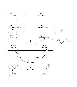
[0028] FIG. 4 shows a mechanical drawing for implementing a jump-starter, in
accordance with an embodiment of the present invention. Various system
components are
shown, including LEDs, a buzzer, a recharging port, and a stopper tap switch
mounted on a
circuit board. FIG. 4 may be reflective of the schematic of FIG. 3 in one or
more aspects.
[0029] FIG. 2 shows a flow chart 200 of a method for jump-starting a vehicle
battery,
in accordance with an embodiment of the present invention. The steps of the
flow chart 200
may be performable, for example, by a system such as system 100 (or a portion
thereof).
Furthermore, the steps of method 200 may be performable in a different order,
or some steps
may be omitted, or some steps may be performed in parallel according to design
preferences.
For example, step 245 may be performed before step 205, or step 245 may be
performed in
parallel with step 240. Method 200, or a portion thereof, may be performable
by one or more
processing units. Method 200, or a portion thereof, may be performable by
software,
7
CA 02790505 2012-08-16
WO 2011/106343 PCT/US2011/025806
hardware, and/or firmware. Method 200, or a portion thereof, may also be
expressible
through a set of instructions stored on one of more computer-readable storage
media, such as
RAM, ROM, EPROM, EEPROM, optical disk, magnetic disk, magnetic tape, and/or
the like.
[0030] At step 205, a switch may be toggled to enable or disable an audible
alert. As
discussed, the audible alert may be enabled or disabled through various
possible
configurations and styles of the switch. The switch 150 may toggle to enable
or disable the
audible alert by opening or closing one or more connections.
[0031] At step 210, a voltage of a jump-starter battery may be measured. For
example, the voltage of the jump-starter battery may be measured by a voltage
comparison
circuit. At step 215, a reference voltage may be established. The reference
voltage may be
established by a voltage reference (for example a zener diode) or may be
established as a
proportion or ratio of a voltage reference. At step 220, the voltage of the
jump-starter battery
and the reference voltage may be compared. For example, the comparison may be
performed
by the voltage comparison circuit. At step 225, it may be determined whether
the jump-
starter battery voltage is less than the reference voltage. The determination
may be
performed by the voltage comparison circuit. At step 230, if the jump-starter
battery voltage
is less than the reference voltage, and if the switch is toggled to enable the
audible alert, then
an audible alert may be generated. The audible alert may be generated by an
alert circuit in
conjunction with a speaker, in accordance with these conditions.
[0032] At step 235, a pair of connectors may be electrically connected between
the
jump-starter battery and a vehicle battery. At step 240, the vehicle battery
may be recharged
when the connectors are connected.
[0033] At step 245, a visual indicator corresponding to the voltage of the
jump-starter
battery may be displayed. The visual indicator may be displayed by a display
circuit. The
visual indicator may operate whether or not there is a potential alert
condition. The visual
indicator (either the same or a different visual indicator) may also operate
to provide a visual
alert in conjunction with the audible alert. At step 250, a system may be
provided that is
capable of performing steps 205-240, and the system may be shipped with the
switch toggled
to disable the audible alert during the shipping process.
[0034] To illustrate an example, the flow chart 200 may be implemented in the
following manner. At step 205, a switch is toggled to enable an audible alert.
At step 210, a
jump-starter battery voltage is measured to be 10.3 Volts by a voltage
comparison circuit. At
step 215, a reference voltage of 10.5 Volts is established by the voltage
comparison circuit
130. The reference voltage of 10.5 Volts is proportional to a voltage across a
zener diode in
8
CA 02790505 2012-08-16
WO 2011/106343 PCT/US2011/025806
the voltage comparison circuit. The reference voltage also has an associated
tolerance of
0.5 Volts. At steps 220 and 225, the voltage comparison circuit then compares
and
determines that the jump-starter battery voltage of 9.8 Volts is less than the
reference voltage
of 10.5 Volts and outside the tolerance of 0.5 Volts. At step 230, an audible
alert is
generated by an alert circuit and a speaker. Looping back to step 205, the
switch is toggled to
disable the audible alert. The voltage comparison circuit and the alert
circuit are, as a result,
disabled. Therefore, the audible alert will cease.
[0035] Thus, embodiments of the present invention provide for systems and
methods
for alerting that a jump-starter battery lacks sufficient charge to recharge
another battery.
[0036] While the invention has been described with reference to certain
embodiments, it will be understood by those skilled in the art that various
changes may be
made and equivalents may be substituted without departing from the scope of
the invention.
In addition, many modifications may be made to adapt a particular situation or
material to the
teachings of the invention without departing from its scope. For example,
features may be
implemented with software, hardware, or a mix thereof. Therefore, it is
intended that the
invention not be limited to the particular embodiment disclosed, but that the
invention will
include all embodiments falling within the scope of the appended claims.
9