Note : Les descriptions sont présentées dans la langue officielle dans laquelle elles ont été soumises.
LIGHT FIXTURE WITH PERIPHERAL COOLING CHANNELS
CROSS-REFERENCE TO RELATED APPLICATIONS
BACKGROUND
[0002] The present invention relates to light fixture cooling features, and
particularly, to
providing a light fixture with external surface features to facilitate
cooling.
[0003] Managing the temperature of light sources in a light fixture is
generally important
to performance and longevity. This is particularly true with newer highly
efficient lighting
technology, for example, light sources such as LEDs or laser diodes. LEDs are
generally
selected to maximize the light output for a given power consumption at a
reasonable cost.
Because LED light sources operate at a much lower temperature than typical
incandescent
light sources, less energy is wasted in the form of heat production. However,
LEDs tend to
be more sensitive to operating temperature and lower operating temperatures
also provide a
much smaller temperature difference between the LED and the ambient
environment, thus
requiring greater attention to thermal management to transfer and dissipate
any excess heat
generated by the LED driver and emitter so that the design operating
temperature for the
components are not exceeded.
[0004] As temperatures rise, the efficacy of the LED is reduced, reducing
the light
output, and reducing the lifespan of the LED. LED lighting fixtures generally
include both
CA 2792815 2017-09-15
LED drivers and LED emitters. To facilitate dissipation of heat, convection,
conduction, and
radiation are available modes of heat transfer. For LED light fixtures,
dissipation of heat by
conduction is often provided by one or more LED packages being mounted on a
heat sink.
The heatsink is generally integral with or thermally coupled with the light
housing, which
often includes external cooling fins to further facilitate the dissipation of
heat from the light
fixture by convection and radiation.
[0005] Many prior designs seeking to address these concerns provides a set
of fins
forming vertical airflow channels extending radially around a light emitter
and driver
housing; however, the fins forming the airflow channels only abut vertical
edges of the
housing.
[0006] Therefore, it is desirable to provide a lighting fixture design in a
unitary fixture
that maximizes cooling by thermal convection for the light housing, including
convection
from horizontal surfaces of the housing, and shields the cooling features from
as many
viewing angles as practical. Additionally, for some lighting fixture designs,
it is also
desirable to minimize thermal conduction between emitter and driver housings.
SUMMARY
[0007] The present invention may comprise one or more of the features
recited in the
description, and/or one or more of the following features and combinations
thereof.
[0007a] According to the present invention, there is provided a light
fixture for a light
emitter, comprising:
an emitter housing;
2
CA 2792815 2017-09-15
an illumination side of the emitter housing, the light emitter projecting
light from
the illumination side;
an opposite side of the emitter housing, located opposite the illumination
side;
first and second edges defined by the emitter housing, each of the first and
second edges spanning between the illumination and opposite sides;
a first rim positioned along the first edge of the emitter housing and
spanning
between the illumination and opposite sides;
a second rim positioned along the second edge of the emitter housing and
spanning between the illumination and opposite sides; and
a first plurality of fins spanning between the first edge and the first rim,
the first edge
and the second edge, the second edge and the second rim, and the first rim and
the
second rim.
[0007b]
According to the present invention, there is provided a light fixture for a
light
emitter, comprising:
an emitter housing;
an illumination side of the emitter housing, the light emitter projecting
light from
the illumination side;
an opposite side of the emitter housing, located opposite the illumination
side;
first and second edges defined by the emitter housing between the illumination
and opposite sides;
a first rim positioned along the first edge of the emitter housing;
a second rim positioned along the second edge of the emitter housing; and
a first plurality of fins spanning between the first edge and the first rim,
across
2a
CA 2792815 2018-08-23
the opposite side of the emitter housing, and between the second edge and the
second rim.
[0007e] According to the present invention, there is provided a light
fixture for a light
emitter, comprising:
a first housing;
an illumination side of the first housing, the light emitter projecting light
from the
illumination side;
an opposite side of the first housing, located opposite the illumination side;
first and second edges defined by the first housing between the illumination
and
opposite sides;
a rim extending around at least two opposite edges of the first housing;
a first plurality of fins spanning between the rim and the at least two
opposite
edges of the housing and across the opposite side of the first housing; and
a plurality of airflow channels, each of the plurality of airflow channels
defined
between adjacent ones of the first plurality of fins, each of the plurality of
airflow
channels open to the illumination side of the first housing between the rim
and a
first one of the at least two opposite edges of the first housing, extending
across
the opposite side of the first housing, and open to the illumination side of
the
housing between the rim and a second one of the at least two opposite edges of
the first housing.
[0007d] Preferred embodiments of the invention are described hereunder.
2b
CA 2792815 2018-08-23
100081 An illustrative light fixture includes an emitter housing and
airflow cooling
channels. The airflow cooling channels are defined in the space between
opposite edges of
the emitter housing and a rim around the periphery of at least the opposite
edges of the
2c
CA 2792815 2017-09-15
CA 02792815 2012-10-09
emitter housing. The airflow channels are further defined by fins spanning
between the rim
and opposite edges and spanning across a side of the housing opposite the
illumination side.
[0009] An illustrative embodiment of a light fixture for a light emitter
includes an
emitter housing; an illumination side of the emitter housing, the light
emitter projecting light
from the illumination side; an opposite side of the emitter housing, located
opposite the
illumination side; a first and second edge defined by the emitter housing,
each of the first
and second edges spanning between the illumination and opposite sides; a first
rim
positioned along the first edge of the emitter housing and spanning between
the illumination
and opposite sides; a second rim positioned along the second edge of the
emitter housing and
spanning between the illumination and opposite sides; and a first plurality of
tins spanning
between the first edge and the first rim, the first edge and the second edge,
the second edge
and the second rim, and the first rim and the second rim.
100101 The light fixture can further include a plurality of airflow
channels, each of the
plurality of airflow channels defined between adjacent ones of the first
plurality of fins, each
of the plurality of airflow channels open to the illumination side of the
emitter housing
between the first rim and the first edge, extending across the opposite side
of the emitter
housing, and open to the illumination side of the emitter housing between the
second rim and
the second edge.
[0011] In one illustrative embodiment, the light fixture further includes a
driver housing,
the driver housing defining a front surface; and an airflow passage defined by
a space
between the opposite side of the emitter housing and the front surface of the
driver housing;
and wherein the first plurality of fins extend through the airflow passage.
The light fixture
3
can further include a second plurality of fins defined by the driver housing.
The first
plurality of fins and the second plurality of fins can form a plurality of
coplanar fins
surfaces.
[0012] A plane formed across the first rim and the second rim can
optionally not be
intersected by the first plurality of fins. A plane formed across the first
rim and the second
rim can optionally not be intersected by the first edge or the second edge.
The first plurality
of fins can be in thermal conductivity with the light emitter.
[0013] The first rim and the second rim can be on opposite sides of the
emitter housing.
The first plurality of fins can be parallel with one another. The first
plurality of fins can be
evenly spaced. The light fixture can further include a top surface defined by
the emitter
housing, and the top edges of the first plurality of fins can be coplanar with
the top surface of
the emitter housing.
[0014] Another illustrative embodiment of a light fixture for a light
emitter includes an
emitter housing; an illumination side of the emitter housing, the light
emitter projecting light
from the illumination side; an opposite side of the emitter housing, located
opposite the
illumination side; a first and second edge defined by the emitter housing
between the
illumination and opposite sides; a first rim positioned along the first edge
of the emitter
housing; a second rim positioned along the second edge of the emitter housing;
and a first
plurality of fins spanning between the first edge and the first rim, across
the opposite side of
the emitter housing, and between the second edge and the second rim.
[0015] In one illustrative embodiment, the light fixture further includes a
driver housing,
the driver housing defining a front surface; and an airflow passage defined by
a space
4
CA 2792815 2017-09-15
CA 02792815 2012-10-09
between the opposite side of the emitter housing and the front surface of the
driver housing;
and wherein the first plurality of fins extend through the airflow passage.
The light fixture
can further include a second plurality of fins defined by the driver housing.
The first
plurality of fins and the second plurality of fins can form a plurality of
coplanar fins
surfaces. -
[0016] Another illustrative embodiment of a halt fixture for a light
emitter, includes a
first housing; an illumination side of the first housing, the light emitter
projecting light from
the illumination side; an opposite side of the first housing, located opposite
the illumination
side; a first and second edge defined by the first housing between the
illumination and
opposite sides; a rim extending around at least two opposite edges of the
first housing; a first
plurality of:fins spanning between the rim and the at least two opposite edges
of the housing
and across the opposite side of the first housing; and a plurality of airflow
channels, each of
the plurality of airflow channels defined between adjacent ones of the first
plurality of fins,
each of the plurality of airflow channels open to the illumination side of the
first housing
between the rim and a first one of the at least two opposite edges of the
first housing,
extending across the opposite side of the first housing, and open to the
illumination side of
the housing between the rim and a second one of the at least two opposite
edges of the first
housing.
[0017] In on illustrative embodiment the light fixture further includes a
second housing,
the second housing defining a front surface; and an airflow passage defined by
a space
between the opposite side of the first housing and the front surface of the
second housing;
and wherein the first plurality of fins extend through the airflow passage.
The light fixture
CA 02792815 2012-10-09
can further include a second plurality of fins defined by the second housing.
The first
plurality of fins and the second plurality of fins can form a plurality of
coplanar fins
surfaces.
[0018] Additional features of the disclosure will become apparent to those
skilled in the
art upon consideration of the following detailed description of the
illustrative embodiment.
BRIEF DESCRIPTION OF THE DRAWINGS
[0019] The detailed description particularly refers to the accompanying
figures in which:
[0020] Fig. 1 is a bottom perspective view of a first illustrative lighting
fixture according
to the present invention;
100211 Fig. 2 is a front perspective cross-sectional view of the lighting
fixture of Fig. 1,
taken along section line 2-2 shown in Figs. 3 and 4;
[0022] Fig. 3 is a top view of the lighting fixture of Fig. 1;
[0023] Fig. 4 is a side view of the lighting fixture of Fig. I;
[0024] Fig. 5 is a front view perspective view of a second illustrative
lighting fixture
according to the present invention;
[0025] Fig. 6 is a side perspective cross-sectional view of the lighting
fixture of Fig. 5,
taken along section line 6-6 shown in Fig. 7; and
[0026] Fig. 7 is a rear perspective view of the lighting fixture of Fig. 5;
DESCRIPTION OF THE ILLUSTRATIVE EMBODIMENTS
6
CA 02792815 2012-10-09
100271 For the purposes of promoting and understanding the principals of
the invention,
reference will now be made to one or more illustrative embodiments illustrated
in the
drawings and specific language will be used to describe the same.
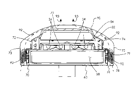
100281 Referring to Figs. 1-4, a first illustrative embodiment of a light
fixture 30
according to the present invention is illustrated. The light fixture 30
includes a light source
32, including an emitter 34 (Fig. 2; as used herein, "emitter" refers to a
single emitter or an
array of emitters) and a driver 36 (not shown; as used herein, "driver- refers
to a single
driver or an array of drivers), and an emitter housing 52. For example, light
source 32 may
be, but is not limited to, an LED emitter 34 and associated driver 36, as are
typically used in
the commercial lighting industry. For example, the associated driver 36
converts AC power
to appropriate DC power and may also include additional LED power and control
features.
100291 The emitter housing 52 can be formed from, for example, die cast
aluminum or
an aluminum alloy. The emitter 34 can be thermally coupled and mounted to the
emitter
housing 52. As it typical of commercial lighting fixtures, the emitter housing
52 may also
include components that enclose the emitter 34 within emitter housing 52, for
example,
including a light reflector 54, lens 58, and frame 60. In the first
illustrative embodiment of
the light fixture 30, the driver 36 (not shown) is also located within the
emitter housing 52.
100301 Referring to Figs. 2, 3, and 4, the emitter housing 52 defines an
illumination side
70 from which the light source 32 projects light (for example, in the first
embodiment
defined by the frame 60 and lens 58), an opposite surface or back side 71, a
left side edge 72,
and a right side edge 74. The light fixture 30 also includes a rim 76 around
the periphery of
the light housing 52, including a left rim 73, a right rim 75, a top rim edge
77, a bottom rim
7
CA 02792815 2012-10-09
edge 78, and an interior surface 79. In the first illustrative embodiment, the
left rim 73 is
spaced apart from the left side edge 72 of the housing 52, the right rim 75 is
spaced apart
from the right side edge 74, and the remainder of the rim 76 on front and rear
sides contacts
the housing 52.
[0031] The light fixture 30 also includes a plurality of fins 90, for
example, in the first
embodiment defined at least in part by the back side 71 of the emitter housing
52, thus, the
plurality of fins 90 are in thermal conductivity with the emitters 34 and
dissipate heat from
the emitters to the surrounding environment.
100321 Referring to Figs. 2 and 3, in the first illustrative embodiment of
the light fixture
30, airflow cooling channels 92 are defined by the space between opposite side
edges 72 and
74 of the emitter housing 52 and the opposite sides of the rim 73 and 75, and
each adjacent
fin 90. The cooling channels 92 extend vertically from the bottom rim edge 78
to the top
rim edge 77 and allow air to flow between the illumination side 70 and the
back side 71, for
example, typically heating of the housing 52 would draw air from the
illumination side to the
back side 71. Optionally, the fins 90 and associated channels 92 can be
parallel, and/or
evenly spaced, as shown in Fig. 3.
100331 Additionally, as shown in Figs. 2-4, in the first embodiment of the
light fixture
30, the airflow cooling channels 92 spanning between the opposite rims 73 and
75 and edges
72 and 74 (Fig. 2), specifically spanning across a back side 71 of the housing
between
adjacent fins 90, allowing airflow 93 (Fig. 2) to travel upward from the
illumination side 70
of each side 72 and 74 and across the back side 71. If the light fixture 30 is
mounted to
illuminate upward, for example, against a ceiling (not shown), mounted with
the back side
8
71 facing downward and the illumination side 70 upward, then the direction of
airflow 93
would typically be reversed.
[0034] Advantageously, the rims 73 and 75 provide the added functionality
of providing
support to the fins 90 where they extend beyond the left and right side edges
72 and 74 of
the emitter housing 52, more surface area for convective and radiant heat
transfer to the
surrounding air, and providing a more aesthetically appealing appearance of
the light fixture
30, limiting the spiny look while retaining the needed cooling fins 90
projecting beyond the
housing 52 by providing the rim 76. For example, the rims 73 and 75 conceal
portions of the
light fixture 30 because the side edges 72 and 74 of the housing 52 and the
fins 90 do not
extend below (in the direction of the illumination side 70) a plane 94 (Fig.
4) formed by the
bottom edges 78 of the rims 73 and 74.
[0035] Referring to Figs. 5-7, a second illustrative embodiment of a light
fixture 130
according to the present invention is illustrated. The features described
above for the first
embodiment of the light fixture 30 may also be selectively incorporated in the
light fixture
130.
[0036] Referring to Fig. 6, the light fixture 130 includes a light source
132, including an
emitter 134 and a driver 136, an emitter housing 152, and a driver housing
182. The emitter
housing 152 and driver housing 182 can be formed from, for example, die cast
aluminum or
an aluminum alloy. The emitter 134 can be thermally coupled and mounted to the
emitter
housing 152, and the driver 136 can be thermally coupled and mounted to the
driver housing
182. As it typical of commercial lighting fixtures, the emitter housing 152
may also include
9
CA 2792815 2017-09-15
CA 02792815 2012-10-09
components that enclose the emitter 134 within emitter housing 152, for
example, including
a light reflector 154, lens 158, and frame 160.
100371 The emitter housing 152 defines an illumination side 170 (Fig. 6)
from which the
light source 132 projects light, an opposite surface or back side 171, a
bottom side edge 172,
and a top side edge 174. The light fixture 130 also includes a rim 176 around
the periphery
of the emitter housing 152, including a bottom rim 173, a top rim 175, a rear
rim edge 177, a
front rim edge 178, and an interior surface 179. In the second illustrative
embodiment, the
bottom rim 173 is spaced apart from the bottom side edge 172 of the housing
152, the top
rim 175 is spaced apart from the top side edge 174, and the remainder of the
rim 176 on left
and right sides contacts the housing 152.
100381 The light fixture 130 also includes a plurality of emitter fins 190,
for example, in
the first embodiment defined by the back side 171 of the emitter housing 152,
thus, the
plurality of emitter fins 190 are in thermal conductivity with the emitters
134 and dissipate
heat from the emitters to the surrounding environment.
[0039] The driver housing 182 defines surfaces including a front side 184,
which faces
the back side 171 of the emitter housing 152, atop side 185, a rear side 186,
and a bottom
side 187. Referring to Figs. 6 and 7, a plurality of driver fins 188 are
defined by the driver
housing 182 and span from the intersection of the front side 184 and top side
185, across the
rear side 186, to the intersection of the front side 184 and the bottom side
187. The plurality
of driver fins 188 are in thermal conductivity with the driver 136 and
dissipate heat from the
driver to the surrounding environment. Each of the driver fins 188 can be
coplanar with
respective ones of the emitter fins 190, as is shown most clearly in Fig. 7.
Referring to Fig.
CA 02792815 2012-10-09
6, a space 196 is defined between the rear side 171 of the emitter housing
152, and the front
side 184 of the driver housing 182, and will be further referenced below.
100401 As with the first illustrative embodiment, in the second
illustrative embodiment
of the light fixture 130, airflow cooling channels 192 are defined by the
space between
opposite side edges 172 and 174 of the emitter housing 152 and the opposite
sides of the rim
173 and 175, and each adjacent fin 190. The cooling channels 192 extend from
the front rim
edge 178 to the rear rim edge 177 and allow air to flow between the
illumination side 170
and the back side 171. Optionally, the fins 190 can be parallel, and/or evenly
spaced, as
shown in Fig. 7.
100411 Additionally, as shown in Fig. 6, in the second embodiment of the
light fixture
130, the airflow cooling channels 192 span between fins 190 through the space
196.
Specifically, the cooling channels 192 span between the opposite rims 173 and
175 and
edges 172 and 174, between and across a back side 171 of the emitter housing
152 and front
side 184 of the driver housing 182.
100421 Additionally, as shown in Figs. 6 and 7, the airflow from cooling
channels 192
can flow not only through the space 196, but around the driver housing 186 in
the channels
198 defined by adjacent driver fins 188. The channels 198 can extend fully
around the
driver housing 186, from the intersection of the front side 184 and top side
185, across the
back side 186, and to the intersection of the front side 184 and the bottom
side 187.
[0043] While the invention has been illustrated and described in detail in
the foregoing
drawings and description, the same is to be considered as illustrative and not
restrictive in
character, it being understood that only illustrative embodiments thereof have
been shown
11
and described and that all changes and modifications that come within the
spirit and scope of the
invention as defined in the description and summary are desired to be
protected.
12
CA 2792815 2017-09-15