Note : Les descriptions sont présentées dans la langue officielle dans laquelle elles ont été soumises.
CA 02793104 2016-09-22
METHOD AND APPARATUS FOR PROCESSING OF CARBON-
CONTAINING FEED STOCK INTO GASIFICATION GAS
[0001] The invention relates to chemical technology and equipment, in
particular,
to processes and apparatuses for processing of solid household and industrial
waste,
fossil fuels as well as other carbon-containing feedstock into gasification
gas by use of
pyrolysis and downdraft gasification processes.
BACKGROUND
[0003] The downdraft gasification process has a number of advantages
compared to
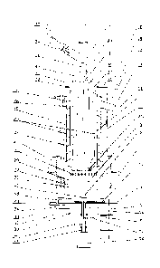
the updraft gasification process, which is the process typically used in
modern
technologies for processing of carbon-containing feedstock. One such advantage
of the
downdraft gasification process is that process tars, acids and steam, which
are formed
in a low temperature pyrolysis zone, go through the combustion and reforming
zones
where, under the exposure to high temperatures, they reach almost a complete
conversion into gasification gases. This makes it possible to use said gases
for
production of electric energy in gas-diesel engines, gas powered engines or
gas
turbines, for example, with minimal costs for cooling and purification of said
gases.
[0004] At the same time, the traditional downdraft gasification process
is
characterized by some disadvantages that have prevented a more widespread use
of that
process. Some of the disadvantages of the traditional downdraft gasification
process
that have been described in the technical and scientific literature are: (1)
the
impossibility of use of the downdraft process for processing of plasticizing
and coking
feedstock with high content of volatile components due to the chocking-up of
the
feedstock in a bunker for drying and low temperature pyrolysis, which, in
turn, results
in an unstable gasification process followed by its complete shut-down; (2)
the
impossibility to operate with feedstock having fine or large fraction,
feedstock
representing aggregate pressed body, or feedstock with high ash content having
low
1
CA 02793104 2012-09-13
WO 2011/115770
PCT/U52011/027409
temperature of ash melting; (3) the necessity to shut-down the process for
periodic
loading or additional loading of feedstock, its manual crushing and pushing
through
(which is has been referred to as "poking"), (4) the need for periodic removal
of
residual ash and/or slag residue; (5) heterogeneity of v and compositions of
the
produced gases due to the stoppage for loading of the feedstock, which makes
it more
difficult to utilize such gases; (6) a low relative productivity of gasifiers
caused by the
air flow supply with parameters that do not allow to start the intensive slag
formation
process; (7) production of toxic inorganic ash residuals; (8) inability to
effectively
utilize the heat of the produced gases for improving the gasifier efficiency;
and (9)
significant heat losses.
SUMMARY
[0005] The following is a summary description of illustrative embodiments
of the
invention. It is provided as a preface to assist those skilled in the art to
more rapidly
assimilate the detailed discussion, which ensues, and is not intended in any
way to limit
the scope of the claims, which are appended hereto in order to particularly
point out the
invention.
[0006] One embodiment of the apparatus of the instant invention comprises
an
external vessel and an external vessel, wherein the internal vessel is located
inside the
external vessel, thereby forming a void between the internal and external
vessels. The
apparatus also comprises a loading mechanism with an elongated loading
mechanism
trunk and a feedstock feeder for moving the feedstock along the elongated
loading
mechanism trunk. The apparatus further comprises a gasifier trunk, a fire
chamber, a
gas outlet and a slag discharge mechanism.
[0007] The operation of the apparatus described above comprises a
continuous
supply of feedstock into the gasifier trunk, where the feedstock is supplied
under
pressure created by the loading mechanism, which causes a movement of the
feedstock
along the loading mechanism trunk and the gasifier trunk and allows for
unhindered
passage of the formed gases and residual carbon through all processing zones
followed
by the cooling, mechanical crushing and removal of slag.
2
CA 02793104 2012-09-13
WO 2011/115770
PCT/US2011/027409
[0008] One embodiment of the new method of the instant invention comprises
the
steps of providing a loading mechanism trunk, providing a drying zone,
providing a
plasticization zone, providing a pyrolysis zone, providing a combustion zone,
providing
a reforming zone, providing a slag discharge zone, supplying feedstock,
forcing said
feedstock through said loading mechanism trunk as well as through each of said
drying
zone, pyrolysis zone, combustion zone, reforming zone, and slag discharge zone
with a
loading a loading mechanism that comprises an elongated loading mechanism
trunk
and a feedstock feeder. Said method further comprises the steps of causing
said
feedstock to form a plug that substantially hermetically separates said drying
zone, said
plasticization zone, said pyrolysis zone, said combustion zone, said reforming
zone
and said slag discharge zone from the atmosphere and causing formation and
separation
of steam from said feedstock in said drying zone, causing pyrolysis gases to
form in
said pyrolysis zone, separating substantially all of said pyrolysis gases from
said
feedstock in said pyrolysis zone, thereby causing separation of carbon char
residue and
forming gasification gases.
BRIEF DESCRIPTION OF THE DRAWINGS
[0009] Fig. 1 presents a schematic depiction of an apparatus pursuant to
one
embodiment of the present invention.
[0010] Fig. 2 is a symbolic depiction of the distribution of the
functional zones in
an apparatus that implements one embodiment of the method of the present
invention.
[0011] Fig. 3 is a flowchart of one embodiment of the method of the present
invention.
DETAILED DESCRIPTION
[0012] The present invention relates to a method and apparatus for
processing
carbon-containing feedstock into gasification gases. The following description
is
presented to enable one of ordinary skill in the art to make and use the
invention and is
provided in the context of this description and its requirements. Although the
present
invention will be described in the context of a method and apparatus for
processing
household and industrial waste, various modifications to the preferred
embodiment will
3
CA 02793104 2012-09-13
WO 2011/115770
PCT/US2011/027409
be readily apparent to those skilled in the art, and the principles described
herein may
be applied to other carbon-containing feedstock, embodiments of the appartus
and
modifications of the method.
[0013] The present invention allows
to process feedstock with various
morphological structures, fractioned composition, and increased moisture
content that
was impossible to reliably and efficiently process in a downdraft process by
the
previously-known methods.
[0014] Referring to Fig. I, one
embodiment of the apparatus of the present
invention comprises: external vessel 1, internal vessel 2, fire chamber 3,
loading
mechanism trunk 4, and slag discharge mechanism 5.
[0015] The external vessel 1 is
preferably made of sheet heat-resistant steel in a
form of a cylinder, but it may be made of another heat-resistant material and
may have
a non-cylindrical shape. Cooling flange 10 is attached to the lower end of
external
vessel 1 with preferably annular air cooling channel 11. Flange 12 is attached
to the
upper end of external vessel I. Gas outlet 13, preferably characterized by a
rectangular
or round cross-section, is positioned tangentially to external vessel 1. Gas
outlet 13 is
intended for discharging produced gasification gases from the apparatus of the
instant
invention.
[0016] Thermal jacket 14 is
preferably positioned on the outer surface of external
vessel 1. Air channels 15 are formed in thermal jacket 14. Thermal isolation
jacket 14
is preferably equipped with external casing 16 and landing pads 17. In an
alternative
embodiment, external casing 16 may be fabricated as two cylindrical shells of
different
diameter connected together by a rigid concentric bridge and attached to lower
flange
10. Cover 18 is attached to upper Flange 12. Flange 19 is positioned on the
lower
portion of cover 18, Air distribution box 20 is attached to the upper surface
of flange
19. Flange 19 is coupled with flange 12. Flange 19 is also connected to the
upper
portion of internal vessel 2.
[0017] The body 9 of slag
discharge mechanism 5 is attached to lower flange 10.
Flange 23 with air cooling channel 24 is positioned above slag discharge
mechanism 5.
4
CA 02793104 2012-09-13
WO 2011/115770
PCT/US2011/027409
Air channels 48 pass through flanges 10 and 23 and connect air cooling
channels 11
and 24.
[0018] In this embodiment, internal vessel 2 is characterized by a
cylindrical shape
and is made of sheet heat-resistant steel. Internal vessel 2 is positioned
inside external
vessel I. Internal vessel land external vessel 2 are connected through flange
19. Gas
channel 26 is located between external vessel 1 and internal vessel 2.
[0019] Cover 21 is
connected to the upper portion of internal vessel 2 through
flange 22 with the air distribution shell 20. Fire chamber 3 is located in e
lower
portion of internal vessel 2. Gasifier trunk 8 is located inside internal
vessel 2. Air
supply channels 25 located inside internal vessel 2 connect air distribution
shell 20 with
fire chamber 3. Pipes may be used to form air supply channels 25. Blades of
turbulator
27 are formed on the outer surface of internal vessel 2.
[0020] In the preferred
embodiment, fire chamber 3 is molded of heat-resistant
steel. Alternatively, fire chamber 3 may have a welded structure or may be
another
suitable manner. Fire chamber 3 is characterized by internal wall 28 and
external wall
29. Further, in the preferred embodiment, fire chamber 3 is composed of
cylindrical
shells fixed together by concentric insertions forming an internal volume ¨
under-
tuyere bend 30 connected with air distribution shell 20 by air supply channels
25.
[0021] Internal wall 28
of fire chamber 3 may have a shape of a truncated cone
with a wider diameter at its bottom. Heat-resistant coating may be applied to
the
external surface of fire chamber 3. External tuyeres 31 may be constructed as
nozzles
around the circumference of internal wall 28.
[0022] Internal tuyeres
32 are placed in the central portion of fire chamber 3 at an
angle to the walls of internal vessel 2. Internal tuyeres 32 connected to air
distribution
shell 20 by air supply channels 25.
[0023] Loading
mechanism 7 comprises receiving bunker 33, feedstock supply
channel 34 and loading mechanism trunk 35. Loading mechanism may be equipped
with piston 36 or a suitable mechanical drive of another design. In the
preferred
embodiment, gasifier trunk 8 is placed inside internal vessel 2 such that the
axis of
5
CA 02793104 2012-09-13
WO 2011/115770
PCT/US2011/027409
gasifier trunk 8 substantially coincides with the axis of loading mechanism
trunk 35
and the lower opened edge 4 of loading mechanism trunk 35 is positioned at the
level
or slightly below the upper edge of gasifier trunk 8. The diameter of the
loading
mechanism trunk 351s lesser than the diameter of gasifier trunk 8.
[0024] In an alternative embodiment, a portion of loading mechanism trunk
35 that
is located above cover 21 can be equipped with a cooler. Gasifier trunk 8 is
formed as
a truncated cone widened to the bottom. Degassing slits are preferably formed
in the
walls of gasifier trunk 8. The degassing slits are preferably cut through the
entire
length of the walls of gasifier trunk 8, but may leave uncut portions,
preferably closer
to the mid-portion of gasifier trunk 8. In the preferred embodiment, degassing
slits are
wider toward the lower end of gasifier trunk 8. The diameter of the bottom
portion of
gasifier trunk 81s lesser than the diameter of internal vessel 2.
[0025] In the preferred embodiment, gasifier trunk 8 is reinforced along
its length
with steel rings of various diameters attached to the outside surface of
gasifier trunk 8.
Such steel rings serve as rigidity structures. If the shape of the gasifier
trunk is
different, the rigidity structures will conform to the shape of the gasifier
trunk. For
example, if the gasifier trunk is octagonal, than the rigidity structures will
be octagonal
too. In addition, in the preferred embodiment, gasifier trunk 8 is equipped
with rigidity
ribs positioned on the wall segments separated by the degassing slits.
100261 Damping chamber 37 is formed between internal vessel 2 and
gasifier trunk
8.
[0027] Slag discharge mechanism 5 includes cylindrical body 9. Flange 23
is
attached to the upper portion of cylindrical body 9. Flange 23 is equipped
with air
channels 48. Air distribution box 39 is attached to the inside surface of
bottom 40 of
slag discharge mechanism 5. Air distribution box 39 is preferably of a
cylindrical
shape with bores in its upper portion. A branch pipe of the air supply channel
38 is
inserted through the side wall of slag discharge mechanism 5 and attached
tangentially
to air distribution box 39.
[0028] Slag discharge mechanism 5 is also equipped with table 41.
Rotating slag
scraper 42 is positioned on table 41. Rotating slag scraper 42 is constructed
as a hollow
6
CA 02793104 2012-09-13
WO 2011/115770
PCT/US2011/027409
structure with an air- or water-cooling system inside. Slag scraper 42 is
equipped with
coolant inlet branch pipe 45 and coolant outlet branch pipe 46. Slag scraper
42 is also
equipped with bearing unit 4 and mechanical drive 43. Table 41 is attached to
body 9 of
slag discharge mechanism 5.
[00291 Flange 23 is a continuation of table 41. Air channels 48 are
positioned
between flanges 23 and 10, air channels 48 connect air cooling channel 11 with
tray 24
of slag discharge mechanism 5. One or more slag collection bunkers 47 are
attached to
the lower surface of table 41. Slag collection bunkers 47 are connected to
slag
discharge lock channels 6.
OPERATION OF THE PREFERRED EMBODIMENT
[0030] Feedstock is loaded into the receiving bunker of loading mechanism
33.
Then, batches of feedstock are introduced into feedstock supply channel 34.
Feedstock
may be moved by a piston equipped with a drive. Thus, feedstock batches are
introduced into a preferably inclined feedstock supply channel 34 and then
into loading
mechanism trunk 35. When a batch of feedstock is moved into loading mechanism
trunk 35, piston 36 is located in its upper position. After a batch of
feedstock is
.. introduced into loading mechanism trunk 35, piston 36, driven by its drive,
is brought
down into its lower position, thereby moving feedstock down loading mechanism
trunk
35. An air-tight plug is formed from the feedstock under the pressure exerted
by piston
36 and in conjunction with friction forces between the compressed feedstock
and
internal walls of loading mechanism trunk 35.
[00311 The operation of the drives and the pistons of feedstock supply
channel 34
and loading mechanism trunk 35 is synchronized. That allows for batched supply
of
pressed feedstock in the form of a airtight movable plug into gasifier trunk
8. During
the next loading cycle, a new plug that is formed in loading mechanism trunk
35 pushes
.. the previous one down into gasifier trunk 8. Because the diameter of the
gasifier trunk
8 is greater than the diameter of loading mechanism trunk 35, the feedstock,
in the form
of pressed airtight plugs, brakes down into smaller parts that are spread over
the entire
surface of the upper part of gasifier trunk 8.
7
CA 02793104 2012-09-13
WO 2011/115770
PCT/US2011/027409
[0032] Loading mechanism trunk 35 can be equipped with an external cooler
protecting the airtight plug during the operation and especially during the
shutoffs of
the gasifier from drying up or burnout, which can result in the loss of the
plug air-
tightness. Gasifier trunk 8 is constructed as a truncated cone widened toward
its
bottom. The degassing slits, which are also widened toward ther bottom, allow
to
reduce friction between feedstock (as it moves down gasifier trunk 8) and the
internal
walls of gasifier trunk 8, which, in turn, facilitates the passage of
feedstock through
gasifier trunk 8 into the fire chamber 5.
[0033] Compacted feedstock in gasifier trunk 8 along its entire length is
exposed to
the external heat from the walls of internal vessel 2, which is heated from
the outside
by hot gases produced in the zone of fire chamber 3 and channeled to gas
outlet 13
through the gap between internal vessel 2 and external vessel 1. The
temperature
along gasifier trunk 8 reaches approximately 700 C in its lower portion and
approximately 300-400 C in its upper portion.
[0034] Turbulator 27, which consists of a plurality of metal blades
attached in a
spiral pattern to the external surface of internal vessel 2, intensifies heat
transfer from
upward flow of hot gasification gases to the walls of internal vessel 2.
[0035] Due to the continuing action of piston 36, feedstock inside
gasifier trunk 8
moves down toward fire chamber 3. As it moves down gasifier trunk 8, feedstock
undergoes changes caused by exposure to the heat, Such low-temperature
processing
of feedstock can be roughly divided into three stages: drying, plasticization
and low-
temperature pyrolysis. Thus, gasifier trunk 8 represents a zone of low-
temperature
processing ¨ Zone 1. Fig. 2 schematically demonstrates various zones within
the
apparatus according to this invention:
Zone 1 can be, roughly, divided into three areas:
¨Area 1.1 ¨ feedstock drying zone;
¨ Area 1.2 ¨ plasticization zone; and
¨ Area 1.3 ¨ low temperature pyrolysis porolysis..
[0036] Process steam and pyrolysis gases that contain light tars and
carbon are
formed by low-temperature processing of feedstock in Zone 1. Such steam and
gases
8
CA 02793104 2012-09-13
WO 2011/115770
PCT/US2011/027409
enter into the damping chamber 37 through the degassing slits of gasifier
trunk 8.
Damping chamber 37 is positioned between gasifier trunk 8 and internal vessel
2.
Process steam and pyrolysis gases then enter into the zone of the fire chamber
3
through the gap formed by the difference in the diameters of the lower portion
of
gasifier trunk 8 and internal vessel 2. A airtight plug, formed from feedstock
in
loading mechanism trunk 35, does not allow the discharge into atmosphere of
the
steam-gas mixture formed in Zone 1. The same plug prevents air from the
outside from
entering. Light tars and carbon together with pyrolysis gases, which are
formed in the
zone of the low-temperature pyrolysis (Area 1.3) and which pass through the
degassing
slits of gasifier trunk 8, could block the lower portion of damping chamber
37.
However, the high temperature of approximately 1300 '17 and steam that enters
from
the drying zone (Area 1.1), de-tar the lower portion of damping chamber 37,
thereby
allowing for unobstructed passage of the steam-gas mixture from damping
chamber 37
into fire chamber 3.
[0037] There are no degassing slits in the plasticization zone (Area 1.2).
That is
necessary to ensure that the feedstock, which has changed its aggregate state
from
solid to viscous under the pressure of piston 36, is not pushed out at this
area through
the degassing slits into damping chamber 37, which could create obstacles for
free
passage of the steam-gas mixture.
[0038] Air supply channels 25 are positioned in damping chamber 37, on the
opposite side of the degassing slits of gasifier trunk 8. Air, heated from the
walls of
slag discharge mechanism 5, is supplied from the air distribution shell 20
through air
supply channels 25 to internal tuyeres 32 and is also supplied through the
under-tuyere
bend 30 to the external tuyeres 31.
[0039] Steam and/or carbon dioxide can be introduced into the gasifier as
additional oxidizer through steam inlet 49 located in the upper portion of
damping
chamber 37.
[0040] Internal tuyeres 32 are positioned at the level of the lower edge
of gasifier
trunk 8. Internal tuyeres 32 are installed at an angle, approximately 45
degrees to the
wall of internal vessel 2. The internal tuyeres are attached with plate
holders, which
also provide support for feedstock in gasifier trunk 8 to prevent abrupt
falling of
9
CA 02793104 2012-09-13
WO 2011/115770
PCT/US2011/027409
feedstock into the zone of fire chamber 3. The plate holders also help to
separate
feedstock into segments. That, in turn, facilitates the process of
gasification of residual
carbon in the zone of fire chamber 3 because it makes it possible for the air
coming
from external tuyeres 31 together with the gases coming from damping chamber
37 to
freely penetrate into the pressed feedstock.
[0041] After passing through the zone of low-temperature processing (Zone
1), the
steam-gas mixture and residual carbon, which is divided into segments and
partially
crushed, enter under action of piston 36 into fire chamber 3, wherein the zone
of high-
temperature processing (Zone 2) is located. Zone 2 is characterized by
temperatures
ranging from approximately 1300 F to approximately 2400 F, where steam-gas
mixture and residual carbon are subjected to high temperatures, as shown in
Fig. 2:
¨ Area 2.1 ¨ high-temperature pyrolysis and subsequent gasification zone;
¨ Area 2.2 ¨ combustion zone;
¨ Area 2.3 ¨ reforming zone.
[0042] Fire chamber 3 is positioned in the lower portion of internal
vessel 2 and
consists of a hollow under-tuyere bend 30, comprising the external wall 28 of
fire
chamber 3 and internal wall 29 of the fire chamber 3. Air supply channels 25
are
attached in the upper part of internal wall 29. External tuyeres 31 are
located in the
middle portion of internal wall 29, along its entire perimeter.
[0043] Internal tuyeres 32 are positioned inside fire chamber 3. External
tuyeres 31
and internal tuyeres 32 form the tuyere bends. Residual carbon and steam-gas
mixture
move from damping chamber 37 under the action of piston 36 along the tuyere
bends.
The air, heated from the walls of slag discharge mechanism 5, enters through
air supply
channels 25 into under-tuyere bend 30, where it is further heated while
cooling the
metal structure of under-tuyere bend 30.
[0044] The heated air enters the combustion zone (area 2.2) of fire
chamber 3
through external tuyeres 31 at the rate of approximately 30 to 50 meters per
second.
The heated air is also supplied into the combustion zone through internal
tuyeres 32,
approximately at the same rate. Initially, under the influence of air oxygen
in the
combustion zone, there occurs practically complete combustion of high-energy
gases
CA 02793104 2012-09-13
WO 2011/115770
PCT/U52011/027409
and tars formed in the low-temperature processing (Zone 1) as well as partial
combustion of residual carbon. Due to a significant exothermal effect of
oxidative
reactions in the combustion zone (Area 2.2), the temperature increases sharply
up to
approximately 2700 ¨ 3100 F, which makes it possible to use feedstock with a
high
moisture content as well as to additionally increase the amount of produced
gasification
gases by means of hydro gasification products.
[0045] In turn, increasing moisture content of the feedstock allows to
lower the
temperature in this zone to 1600 ¨ 2400 F. The high speed of air coming from
the
tuyeres greatly intensifies (up to 200%) the combustion of residual carbon
directly in
front of the tuyeres as compared to the overal combustion rate in fire chamber
3. That
allows to loosen up the residual carbon bulk present in the zone of the
tuyeres bend, to
create in the same zone an intensive carbon boiling effect in the gases formed
as a
result of gasification, to intensify the effect of combustion reactions and
primary
reforming reactions in the that zone, which, in turn, significantly improves
the
composition of the produced gasification gases.
[0046] The residual carbon, which was not gasified in the combustion zone
(Area
2.2), descends into the reforming zone (Area 2.3), where it participates in
the secondary
reforming reactions that result in a complete gasification. In this reforming
zone (Area
2.3), the gases and tars of low-temperature processing, which did not react
with air
oxygen in the combustion zone (area 2.2), are finally converted and reduced to
the level
of simple combustible gases under the influence of high temperatures from hot
residual
carbon and slag. The reforming reactions, which take place in the reforming
zone
(Area 2,3), have highly pronounced endothermic character. That results in a
decreased
temperature in that zone as well as in a drop of temperature of the processed
gasification gases to approximately 1300 ¨ 1450 F.
[0047] The inorganic component of the residual carbon in the combustion
zone
(Area 2.2) and in the reforming zone (Area 2.3) acts as a sorbent and actively
participates in the purification of the produced gasification gas from
hazardous
admixtures of heavy metals, sulfur and chlorine compounds, converting them
into
inactive insoluble in water form, i.e., mainly, a complex silicate slag.
11
CA 02793104 2012-09-13
WO 2011/115770
PCT/US2011/027409
[0048] The degree of gas purification as well as slag formation
temperature in these
zones depends directly upon the ingredients of the inorganic components in the
residual
carbon. Therefore, the degree of gas purification as well as the temperature
of slag
formation can be adjusted using inorganic additives in the feedstock, such as
metal
oxides, salts and oxide hydrates thereof, silicon dioxide and others.
[0049] The slag formed in the combustion zone (Area 2.2) is transferred
through
the reforming zone (Area 2.3) into the slag zone (Zone 3) in a liquid, viscous
or solid
state depending on the temperatures in these zones, morphological structure
and
moisture content of feedstock, as well as inorganic feedstock additives and
possible
additional supply of process steam into the gasifier. Slag is cooled, and
mechanically
crushed in the slag zone (Zone 3), with subsequent removal through slag
discharge lock
channels 6.
[0050] Flange 23 connects slag discharge mechanism 5 with the vessel of the
gasifier through the lower flange 10 of the external vessel 1. Through air
channels 48
are positioned between flanges 23 and 10, thereby connecting air cooling
channel 11
and tray 24 of slag discharge mechanism 5. The system of air channels allows,
with
help of cold air supplied to the gasifier, reduce the temperatures that affect
flanges 23
and 10, the body and other elements of slag discharge mechanism 5, as well as
the
lower part of external vessel 1, all of which are located in the high-
temperature zone.
[0051] The air, heated in tray 24 of slag discharge mechanism 5, is
supplied
through vertical air channels 15 to air distribution box 20, positioned on
cover 21, from
which air is directed to the internal and external tuyercs of fire chamber 3.
Body 9 of
slag discharge mechanism 5 is attached to table 41 at the point of its
transition to flange
23. Body 9 has bottom 40. Air distribution box 39 is located on internal part
of bottom
40. Air distribution box 39 is preferably made in a shape of a cylinder with
concentric
bores in its cover.
[0052] Air supply channel 38 is introduced through the side wall of body
9 of slag
discharge mechanism 5. Cool ambient air is supplied into the gasifier through
air
supply channel 38. Air supply channel 38 is preferably connected to air
distribution box
39 at an angle to improve air distribution inside air distribution box 39.
Rotating slag
scraper 42 is positioned on table 41. Slag scraper is cooled from by the air
flow air
12
CA 02793104 2012-09-13
WO 2011/115770
PCT/US2011/027409
distribution box 39. Slag scraper 42 may be equipped with its own air or water
cooling
system, coolant inlet 45, coolant outlet 46, bearing block 44 and mechanical
drive 43.
100531 During rotational movements under the action of mechanical drive
43, slag
scraper 42 scrapes off, with its toothed edge, a portion of solid slag above,
whereas it
also scrapes off, with its front sharpened edge, the slag from the surface of
table 41,
which slag enters in molten form, but subsequently solidifies on the surface
of table 41
as a result of cooling by the air continuously supplied into tray 24. Slag is
crushed and,
under the action of a centrifugal rotation force of slag scraper 42, is thrown
to the
.. periphery of table 41, where one or more slag accumulation 47 bunkers are
located.
Slag accumulation bunkers are connected with slag discharge lock channels 6.
Thus,
slag accumulation bunkers 47 are filled with crushed slag. Subsequently, the
upper
slide gate of the lock device opens (not shown in Fig. 1) and the slag is
discharged into
the lock device, thereby emptying for slag accumulation bunker 47. Then, the
upper
slide gate closes and the lower slide gate opens (not shown on drawings),
thereby
emptying slag from the lock. The slag then is further directed by the
transporter into the
bunker of slag accumulation (not shown on drawings). This process allows to
discharge the slag practically without any access of ambient air into the
gasifier.
[00541 After passing the high-temperature processing zone, the gasification
gases
enter into the gas zone ¨ Zone 4, which is located in the area between
external vessel 1
and internal vessel 2. While ascending from the bottom upward through the void
between internal vessel 2 and external vessel 1 from the lower portion of fire
chamber
3 to gas outlet 13, the gas flow is cooled down to the temperature of
approximately
300-400 C due to the convective heat transfer in the zone of low-temperature
processing (Zone 1) through internal vessel 2. To facilitate heat exchange,
turbulator 27
is installed in the gas zone (Zone 4).
[0055] The gas flow, ascending from the bottom upward, enters into
Turbulator 27,
.. where it changes direction of its movement while moving in a spiral
trajectory around
internal vessel 2. Thereby, both the linear speed and the turbulence of the
gas flow are
increased. These two factors, together with the increased heat exchange
surface (due to
the surface of the blades of turbulator 27), significantly improve the heat
transfer rate
between the gases and internal vessel 2, thereby transferring the maximum
amount of
13
CA 02793104 2012-09-13
WO 2011/115770
PCT/US2011/027409
heat from the gasification gases to the feedstock in the low-temperature
processing
zone (Zone 1).
[0056] To avoid additional resistance to the flow of the gases coming out
of the
turbulator 27, gasification gas outlet 13 is preferably attached tangentially
with a
downward incline to external vessel 1, which, together with high velocity of
the gas
flow through gas outlet 13, minimizes the deposition on its lower wall of
carbon and
slag dust that may be present in the gasification gas.
[0057] Gas outlet 13 has external heat insulation and is connected through
a flange
joint with the hot cyclone separator that has a thermal isolation casing
allowing to
minimize heat losses of the gasification gas through the walls of the cyclone
separator
vessel. The hot cyclone separator is used to clean the gasification gases that
exit from
the gasifier from fine-dispersed carbon and slag dust, which is can be
collected in the
receiving bin and removed through a lock device.
[0058] Gasification gas can be further directed to a system for cooling
and fmal
purification, where cooling may be done with the production of process steam
or hot
water, whereas final purification from harmful admixtures may be necessary for
its
further industrial use.
[0059] For a better understanding of the instant invention but without
limiting its
scope, a description of the temperature zones is provided below.
Temperature zones
[0060] Processes of heating, diying, low-temperature and high-temperature
pyrolysis of feedstock take place simultaneously in the apparatus of the
present
invention. In addition, interaction of oxidizing gases with decomposition
products and
residual carbon of feedstock takes place in the apparatus.
[0061] Solid household waste (SHW), as feedstock for a gasifier
apparatus, is an
incredibly diverse and multicomponent composition of organic and mineral
components. Table 1 contains data, upon which the following discussion is
based.
14
CA 02793104 2012-09-13
WO 2011/115770
PCT/US2011/027409
[0062] Organic and mineral components of feedstock are essential for
feedstock
processing. They have a major effect on both the composition of the produced
gasification gases and on the formation of residual slag. Both the composition
and type
of mineral components have an effect on the processing of feedstock. Two main
types
of inorganic components are distinguished: as mechanical admixtures and as
components chemically bonded with feedstock content.
[0063] The first and key type comprises an amount of inorganic components
that
ranges between approximately 6% and approximately 25% of the total weight of
feedstock. This type of components is found in feedstock as mechanical
admixtures,
such as nonferrous and ferrous metals, ceramics, construction waste,
sweepings, glass
and other, forming its mineral portion and comprising the following major
components,
such as: CaCO3, MgCO3, FeCO3, CaSO4, Na2SO4, FeSO4, FeS2, S102, silicates with
various content of main oxides A1203, SiO2, CaO, Na2O, K20 and small content
of
oxides of other metals.
[00641 These components can be symbolically arranged in accordance with
decreasing of their content in feedstock, in the following order:
- SiO2 - dozens of percents;
- Al, A1203, MgO, Fe, F203, CaSiO3, CaCO3 - percents, dozens of
percents;
- Cu, Zn, S, TiO2, FeO, Ni, Pb, Na2SiO3, Sn, CaSO4, MgSO4, CI, S2",
Na2CO3
- percents, tenths of a percent;
- BaO, ZnO, Cd, NaC1, NaPO4, MgCO3, MgSO4, MgSiO3, K3PO4, CaCl2,
MgCl2, K2CO3, Cr, Sb, Sb0 - tenths and hundredths of a percent;
- NaOH, Li0H, W, V205, Cr203, Ni203, Pb0, ZnSiO3, F, S032-, Mn, V,
Mo,
As, Co, Hg, As203, Be0 - less than one hundredth of a percent.
[0065] The second type of inorganic components comprises components
chemically bonded with feedstock and constitutes a lesser amounts of
compounds.
This type of mineral components typically constitutes from 0.47% to 2.81% of
the total
weight of feedstock. Some of such components are, for example, metals and
their
oxides and salts, which are contained in paper, cardboard, wood, and dyes,
contained in
textile waste and polymer materials.
15
CA 02793104 2012-09-13
WO 2011/115770
PCT/US2011/027409
[0066] Zone 1 ¨ low-
temperature processing zone, with temperatures ranging from:
20+700 C; this zone provides for drying, destruction and low-temperature
pyrolysis of
the feedstock introduced into the gasifier. This zone can be roughly divided
by
temperature ranges into 3 areas:
Area 1.1 ¨ drying zone. The temperature range is 20+150 C.
Area 1.2 ¨ plasticization zone. The temperature range is 150+350 C.
Area 1.3 ¨ zone of the low temperature pyrolysis. The temperature range is
350+700 C.
[0067] Area 1.1 ¨ drying
zone, with temperatures ranging from: 20+150 C, located
in the upper part of the loading channel, where the following processes take
place:
- In the cooled portion of the loading mechanism trunk: compacting of
loaded feedstock and formation of an airtight plug, which is, essentially, a
process of briquetting of feedstock;
- In the zone warmed by the heat of the gasification gases in the upper
portion
of the gasifier trunk: initial warming of feedstock and evaporation of free
moisture;
- intensive steam formation; drying of feedstock, within which partial
overheating of steam occurs; beginning of the process for change of
aggregative state of fusible elements of feedstock, softening of local zones
in the feedstock bulk.
[0068] In the context of drying processes, one distinguishes free moisture,
moisture
which is mixed with fuel (i.e., moisture, obtained in direct contact with
water), and
moisture, contained in the structure of feedstock (hygroscopic moisture),
which is
caused by vapor adsorption.
[0069] During the process of heating, the rate of drying quickly increases
to a
constant, and then the period of steady drying rate begins, and, after
achieving of a
hygroscopic state, the stage of a descending drying rate begins. The
evaporation zone
deepens into the bulk of pressed feedstock. At intensive heating of surface
beds and
enrichment of internal beds with moisture occur due to moisture evaporation
from the
surface and its movement into the bulk under exposure of hydrothermal
conductivity.
16
CA 02793104 2012-09-13
WO 2011/115770
PCT/US2011/027409
[0070] During the drying process, the heat conduction coefficient
constantly
decreases. The heat-transfer coefficient, starting with a critical point, also
dramatically
decreases, as the moisture content decreases, which is caused by the deepening
of the
evaporation area and increasing of thermal resistance of dry outer bed of
feedstock.
[0071] These processes lead to the deterioration of warming up of the
internal beds
of feedstock, which results in increasing times for complete drying of
internal beds of
feedstock. Accordingly, the lower limit of the drying area of the entire
feedstock
within the gasifier trunk takes a shape somewhat similar to a truncated cone,
having its
apex in the bottom, as shown in Fig. 2.
[0072] Steam, which is formed as a result of feedstock drying, enters the
damping
chamber through the degassing slits of the gasifier trunk, where, after making
contact
.. with the walls of the internal vessel of the gasifier, it becomes partially
overheated.
[0073] During the entire drying process, the feedstock contracts; in other
words, it
decreases in volume, and its further warming up leads to greater structural
changes.
[0074] Area 1.2 ¨ plasticization zone, with temperature change ranging
from:
300 675 F, is located in the middle warmed portion of the gasifier trunk,
within which
the following processes take place:
- the complete drying of feedstock;
- beginning of processes of decomposition and destruction of organic
polymers;
- change of aggregative state of fusible materials of organic and inorganic
origin, their conversion into plastic or liquid state;
- conversion of the entire feedstock into plastic movable mass; and
- initial formation of tars and saturated and unsaturated hydrocarbons.
[0075] Thus, at the temperature of approximately 120 C, polyethylene
starts to
melt. As the temperature increases, other polymers, representing the fusible
portion of
the feedstock, start to melt. When the temperature reaches approximately 200-
250 C,
all polymers turn into into a liquid substance, which fills in all voids in
the feedstock
17
CA 02793104 2012-09-13
WO 2011/115770
PCT/US2011/027409
bulk. At the same time, the entire feedstock turns into a plastic airtight
substance that
slowly moves down the internal space of the gasifier trunk under the pressure
applied
by the piston of the loading mechanism.
[0076] At the temperature of approximately 390 F, mineral colloids
transition into
a vapor phase. The resulting water vapors break through the viscous mass of
the
feedstock up into the drying zone, and then, together with water vapors formed
in the
drying zone, enter into the damping chamber.
[0077] In the process of structural changes, which take place in the drying
zone, the
entire feedstock contracts significantly and its thermal conductivity
increases, thereby
facilitating faster warming of the entire mass of feedstock, including its
internal
portions. However, the internal portion of feedstock still warms up slower
than the
external one. Therefore, the lower boundary of the plasticization zone and its
upper
boundary, take a shape of a cone of irregular shape with an apex at the
bottom, as
shown in Fig. 2.
[0078] At the temperature of approximately 480 F such gases as carbon
oxide and
dioxide, as well as tar begin to discharge from the feedstock bed. Methane,
heavy
hydrocarbon gases and hydrogen begin to discharge as heating proceeds. Such
gases
break through the viscous bulk of feedstock into the zone of the low
temperature
pyrolysis. Then such gases flow into the damping chamber through the degassing
slits
of the gasifier trunk.
[0079] There are no degassing slits in the area of the gasifier trunk where
the
plasticization zone is located during the operation of the gasifier. This is
done to avoid
feedstock being squeezed out into the damping chamber. However, the steam
formed
in the upper portion of the plasticization zone enter into the damping chamber
through
the degassing slits of the drying zone, while the tars and gases from the
lower portion
of the plasticization zone enter into the damping chamber through the
degassing slits in
the low temperature pyrolysis zone.
[0080] Area 1.3 ¨ the low temperature pyrolysis zone, with temperatures
ranging
from approximately 350 C to approximately 700 C, is located in the lower
warmed
portion of the gasifier trunk. The following processes take place in Area 1.3:
18
CA 02793104 2012-09-13
WO 2011/115770
PCT/US2011/027409
- change of the aggregate state of refractory materials with the transition
thereof into plastic state;
- decomposition and destruction of organic compounds with the
breakage of
covalent bonds in polymers and lattices of organic compounds;
- intensive gas discharge;
- discharge of light tarous substances, solidifying of plastic material and
carbonization thereof, starting with external layers;
- transition of the entire bulk of feedstock into residual carbon;
and
- decomposition of certain organic salts.
[0081] The initial decomposition temperature of feedstock is determined
mainly by
feedstock's individual properties, although it somewhat depends on the heating
conditions. The higher the content of bonded oxygen
that is contained in the
feedstock, the lower is its initial decomposition temperature.
[0082] At the initial heating stages of the feedstock, oxygen-containing
components
are discharged first from it, and the least oxidized tarous substances are
discharged last.
The availability of large amount of oxygen in the feedstock during its heating
leads to
an exothermal effect due to the oxidative reactions that take place. That
leads to
additional heating up of the feedstock, which, in turn, speeds up its
destruction. Said
process is further supported by decomposition of some inorganic salts, which
results in
formation of corresponding oxides, in some cases ¨ oxygen and other salts,
according
to warming up of loaded feedstock:
MgCO3 350-650 C > Mg0 + CO,
2Ca(NO3)2 561 C > 2Ca 0 + 4NO2 +02
2NaNO3 380-500 C > 2NaNO2 + 02
2KNO3 400-520 C > 2KNO2 +02
[00831 Oxidative reactions facilitate the increase of the temperature of
feedstock in
.. that zone that results in the discharge of various decomposition products,
which depend
from morphological structure of feedstock, mainly such as: steam, carbon
dioxide,
carbon oxide, acetic acid, methyl alcohol, formaldehyde, tar, methane, ethane,
propylene and hydrogen and also some other decomposition products.
19
CA 02793104 2012-09-13
WO 2011/115770
PCT/US2011/027409
[0084] The availability
of polymeric materials in the feedstock leads to the
corresponding increase of ethylene and polypropylene yield. At the same time,
polymers are decomposed practically completely without formation of residual
carbon.
[0085] The
aforementioned processes for destruction of feedstock and gas
formation lead to significantly decreasing of feedstock amounts and transition
of its
structure into dense porous carbon form. As the heating process continues,
discharge
of tarous substances and other products, condensable at cooling, is
practically
completed. Although gas formation continues, it continues with a lesser
intensity.
Products of feedstock decomposition, formed as a results of the low
temperature
pyrolysis, enter the damping chamber through the degassing slits of the
gasifier trunk.
In the damping chamber, such products mix with steam from the drying zone and
are
subjected to further warming up under the action of thermal radiation from the
wall of
the internal vessel of the gasifier or from direct contact with it. Tars and
particles of
residual carbon being deposited on the walls of the damping chamber, are
removed by
high external temperatures and steam, which arrives from the drying zone
above.
[0086] The draining of
the liquid fraction to the center of the trunk and the conical
shape of the lower boundary of the zone lying on the solid carbon residue
reduce the
possibility of the plastic mass of the feedstock extruding or of the draining
of the liquid
fraction through the degassing slits of the trunk into the damping chamber.
[0087] Zone 2 ¨ high-
temperature processing zone, with temperatures ranging from
approximately 700 C to approximately 1300 C, which is characterized with
high-
temperature pyrolysis of feedstock and further gasification thereof under
exposure of
air oxygen and other oxidizers into gasification gas.
[0088] This zone is roughly divided by temperature ranges into 3 areas:
- Area 2.1 ¨ high-temperature pyrolysis zone. The approximate
temperature
range is 700-900 C.
- Area 2.2 ¨ combustion zone. The approximate temperature range is 900-
1300 C.
CA 02793104 2012-09-13
WO 2011/115770
PCT/US2011/027409
- Area 2.3 ¨
reforming zone. The approximate temperature range is 800-
1100 C.
[0089] Area 2.1 ¨ high-
temperature pyrolysis zone, with temperatures ranging
from approximately 700 C to approximately 900 C. The following processes
take
place in this zone:
- final gas evolution process;
- turning of residual feedstock into solid porous carbon bulk;
- decomposition and melting of inorganic salts and interaction thereof with
carbon and mineral components of feedstock.
[0090] The destruction
of the fuel organic mass occurs along with formation of a
small amount of methane, hydrogen as well astraces of other hydrocarbon gases.
100911 The temperature of 900-1100 C is the highest temperature at which
the
completion of volatile substances evolution from the solid residual carbon.
[0092] Certain
carbonates are melted in this zone: Na2CO3 ¨ 851 C, K2CO3 ¨
891 C, Li2CO3 ¨ 618 C, and chemically interact with carbon and mineral
components of feedstock:
CaCO3+C 800-850 C
>Ca0+2C0
CaCO3 + SiO2 ___________________ 800 C >CaSiO3 + CO,
CaCO3 +112S CaS + H20 +CO,
2Li2CO3 + SiO2 800-1000 C >Li4SiO4 + 2CO2
2Li2CO3 + A1203 800-900 C >2LiA103 + 2CO2
[0093] Notably, CO and
CO2 concentrations increase in the produced gases. In
addition, certain chlorides are melted. For example: CaCl2 ¨ 787 C, NaCI ¨
801 C.
Molten chlorides and carbonates can form eutectic mixtures with more
refractory salts,
which results in a decrease of the melting temperature of the latter. This
phenomenon
has a significant effect on the subsequent formation of liquid slag with a
decreased
melting temperature.
21
CA 02793104 2012-09-13
WO 2011/115770
PCT/US2011/027409
[0094] Area 2.2 ¨ combustion zone, with temperatures ranging from
approximately
900 C to approximately 1300 C. The following processes take place in n this
zone:
- combustion and heat destruction of the pyrolysis gases with low-
temperature
processing of feedstock;
- combustion of portion of the residual carbon of feedstock;
- crushing of the residual carbon bulk due to gas-dynamic processes,
conversion of the residual carbon into "boiling" bed state;
- separation of the residual carbon;
- reforming of the combustion gases due to the oxidation of residual carbon;
- oxidation processes and reforming reactions of the residual carbon
component; and
- beginning of the process of the residual slag formation.
[0095] The combustion area is the primary gasification zone, where
decomposition
and oxidation of gaseous pyrolysis products occur as well as intensive
interaction of
residual carbon, divided into segments and partially crushed under action of
dividing
plates positioned in the lower part of the gasifier trunk, together with air
oxygen and
other oxidizing gases. Initially only gaseous products are oxidized by the air
oxygen,
and to a lesser degree their interaction with carbon dioxide and steam, which
is
produced during the low-temperature processing of feedstock or supplied to the
gasifier.
[0096] The limiting factor of gas combustion processes under a specific
temperature is the diffusion rate, and for the residual carbon ¨ the surface
area of
heterogeneous phase, the oxygen adsorption rate, and the reaction product
desorption
rate.
[0097] The combustion zone is symbolically identified in the gasification
zone as
Area 2.2, whose lower part contains the reforming zone ¨ Area 2.3. Because gas
formation processes in these zones are complex and interrelated, just like the
processes
of liquid slag formation, it is necessary to consider them together.
[0098] Gasification can be described with simple chemical reactions (1) ¨
(11),
which reflect the complex processes occurring in the combustion zone:
22
CA 02793104 2012-09-13
WO 2011/115770 PCT/US2011/027409
C+02 ¨CO2 +95 407 kCal/mol (1)
2C+02 =2C0 + 55 514 kCal/mol (2)
2C0 + 02 =2CO2 + 135 300 kCal/mol (3)
CO + H20 = CO2 + H2 + 9849 kCal/mol (4)
2C0 +2H 2 = CH 4 +CO2 + 59000 kCal/mol (5)
CH4 -F 202 = CO2 -I- 21/20 + 191 759 kCal/mol (6)
C21/4 + 302 2CO2 2H2 0 + 316 195 kCal/mol (7)
C,H, + 4,502 = 3CO2 + 3H20 + 460 422 kCal/mol (8)
C + H20 = CO + H2 - 30 044 kCal/mol (9)
C + 2H20 = CO2 +112-20195 kCal/mol (10)
C + CO2 = 2C0 ¨ 39 893 kCal/mol (11)
[0099] The combustion
process takes place in the upper part of the fire chamber
under exposure to the air oxygen, which is supplied through external and
internal
tuyeres that form tuyeres plates, within which the combustion zone is
positioned.
[00100] For intensification of the gasification process, air is warmed up as a
result of
cooling of the elements of the gasifier. In addition, steam and/or carbon
dioxide may
be injected into the combustion zone at high velocities. Air injected
through the
tuyeres at a high vecocity (up to 50 meters per second) through the tuyeres,
intensifies
the combustion process of the residual carbon of feedstock. That allows to
raise
temperatures at the initial stage of jet combustion in the portion of the fire
chamber that
is positioned in the area of the air tuyeres, up to approximately 1500 C, due
to a high
exothermal reaction effect (1) ¨ (3), together with burning off of high-
calorie gases and
tars (6), (7), (8), formed in the zone of low-temperature processing of
feedstock and in
the area of high-temperature pyrolysis, depending on the amount of steam and
carbon
dioxide.
[00101] Air oxygen is practically completely consumed in the oxidation
reactions of
the pyrolysis gases and residual carbon with formation of, mainly, carbon
dioxide and
steam, which later plays the main role in the gasification process. Oxidative
gases are
23
CA 02793104 2012-09-13
WO 2011/115770
PCT/US2011/027409
also formed. Interacting with residual carbon, these gases are reduced mainly
to simple
combustible gases by reactions (9) ¨ (11).
[00102] The increase of the temperature in the combustion zone allows to
intensify
hydrogasification reactions (9), (10), due to additional warming up of the
residual
carbon and steam, both of which are produced as a result of the oxidizing
processes.
The increasing temperature in the combustion zone causes an intensification of
the
hydrogasification reaction rates (9), (10) allows to use feedstock with an
increased
moisture content without a need for initial preliminary drying, or to
additionally supply
steam from the outside.
[00103] Similarly, with exposure to the initial high temperatures, a carbon
dioxide
gasification reaction of residual carbon occurs in the jet (11), which allows
to use
carbon dioxide supplied from outside as an additional oxidizer.
[00104] Reactions (9), (10), (11) take place mainly at the second stage of the
jet
combustion process in the combustion zone. These are primary endothermic
reforming
reactions Due to these reaction, the total temperature in the lower part of
the
combustion zone is decreased to 900-1100 C. Then, the action of secondary
reforming reactions (9), (10), (1 1) starts in the reforming zone of the
gasifier, leading to
the gasification of the residual carbon, unreacted in the combustion zone
under
exposure to the residual carbon dioxide and steam, which turns into
combustible
gasification gas.
1001051 The high rate of the hot air being injected through numerous tuyeres
up to
50,000 kilogram per square meter per hour, intensifies the gasification of the
feedstock
in the area of the fire chamber located directly in front of the tuyeres.
That, together
with the increased of amount of heated air introduced into the combustion
zone, allows:
- to cut, break into pieces and loosen the residual carbon, which comes to the
combustion zone from the gasifier trunk as large sintered porous pieces;
- to improve the gas-dynamic properties in the combustion zone due to an
intense boiling effect of the residual carbon in gas, which is a result of
gasification, which in turn allows to avoid the formation of local stagnation
areas in this zone;
24
CA 02793104 2012-09-13
WO 2011/115770
PCT/1JS2011/027409
- to separate the pieces of residual carbon, where larger and
heavier portions
of crushed bulk of the residual carbon descend into the gasification zone,
and smaller portions are gasified in the combustion zone;
- to raise the temperature not only in the area where the tuyeres are located,
but also in the entire combustion zone, which allows to maximally intensify
the gasification process and to increase the degree of tar, acids and complex
hydrocarbon conversion in this zone;
- to double or triple the total intensity of gasification of the
feedstock, e.g.,
increasing the throughput from 500 to 1500 kilograms per square meter per
hour across the entire cross-section of the fire chamber;¨ to produce gases
with improved composition due to their saturation with simple combustible
gases as CO and 112, which leads to a higher level of the hydrogasification
reaction (9), (10) and carbon dioxide gasification (11) passing; and
- to decrease the ballast content in the total volume of the produced gas,
where the ballast is in the form of CO2, H20, 02, and N2, as a product of air
gasification, which in turn allows to more efficiently use the produced
gasification gases for electricity production and other purposes.
[00106] The mineral portion of residual carbon is also cardinally changed,
both
chemically and structurally, in the gasification zone.
[00107] Due to high temperatures, the process of decomposition of salts of the
mineral portion of the residual carbon that started in the low temperature
pyrolysis zone
is significantly intensified in the combustion zone. Because of the action of
the
supplied oxygen, complete or partial oxidation of some metals is possible in
the portion
of the fire chamber that is located in front of the tuyeres:
2Zn + 02 225 >2ZnO
2Cu + 0, 225 >2CuO
4Cr +302 ---->2Cr2 03
3Fe+ 4H20 Fe304 + 4H2
CA 02793104 2012-09-13
WO 2011/115770
PCT/US2011/027409
[00108] Nitrogen N and sulfur S are oxidized to oxides SO2 and NO in the same
zone. Their amounts depend on the starting content of said elements in the
loaded
feedstock and the amount of free air oxygen in the fire chamber.
[00109] In the combustion zone, formation reactions of NE13, H2S, and HC1 and
other gases, which are harmful gas components subject to removal from the
produced
gas, take place.
[00110] Subsequently, at the second stage of combustion, in the process of
primary
reforming reactions, when oxygen is completely consumed for oxidation, a
portion of
oxides is reduced to metals and non-metals under action of the burning hot
carbon:
Fe0 + C woo >Fe+CO
3Fe0 + 2 ________________________ 15 > Fe + H 20
SI02 C,Fe,Fe0 1200 >(Si,Fe)+2C0- ferrosilicon
formation
ZnO +C "Co ________________________ >Zn +CO
[00111] Notably, SO2 and NO are reduced to simple elements ¨ S and N2, which
are
further bonded with oxides and metals with the formation of corresponding
sulfides and
nitrides.
[00112] Also, the reaction of sulfur dioxide ¨ SO2 takes place with the
formation of
hydrogen sulfide ¨ H2S, which later forms corresponding sulfides by
interaction with
metal oxides.
Ca0 + H 2S =CaS + H20
Fe0 + H2 S FeS + H20
ZnO + H 2S 500 ZnS + H20
[00113] Similarly halogens are bonded with the formation of chlorides and
fluorides
of various metals.
Ca0 + 2HCI = CaCl2 + 1120
26
CA 02793104 2012-09-13
WO 2011/115770
PCT/U52011/027409
[00114] NI-I3 can also react with certain oxides and pure metals oxidizing to
nitrogen
or with the formation of nitrides:
211TH3 + 3Mg = Mg3N 2 +3112
2NH 3 + 2AI =2AIN +3H 2
2N113 + 3010 = N2 2Cu + 3H20
[00115] In the presence of some unreacted steam in the gasification zone, the
downdraft process, i.e., - salt hydrolysis, is also possible, but it is
minimized due to the
activation of the hydrogasification process and the presence of large amounts
of free
moisture in this zone.
[00116] The entire process continues in the reforming zone in Area 2.3.
[00117] Area 2.3 ¨ reforming zone with temperatures ranging from approximately
800 C to approximately 1100 C. This zone is characterized with:
- the process of secondary reforming reactions;
- purification of produced gases from hazardous components;
- completion of the process of liquid slag formation;
- processes of final formation of the produced gasification gas composition.
[00118] As a result of processes which take place in the combustion and
reforming
zones, oxides of various metals containing carbon admixtures and small amount
of not
decomposed salts as well as reduced pure metals of minerals portion of
feedstock are
formed. Depending on the starting composition of the feedstock, some amount of
metal alloys may be formed, based on iron, copper and silicon.
[00119] Exposed to high temperatures, portions of metals as oxides as well as
pure
metals and salts thereof can turn into a gaseous state. However, most volatile
metals
and compounds thereof remain in a solid or liquid state. That can be explained
either
by an insufficient time they are present in the high-temperature zone or by
the
formation of other less volatile compounds, e.g., certain sulfides, silicates
and
chlorides.
27
= CA 02793104 2012-09-13
WO 2011/115770
PCT/US2011/027409
[00120] Sulfides, silicates as well as various chlorides formed as a
result of said
reactions actively participate in the formation of liquid residual slag.
[00121] The basic material for the formation of any silicate slag is
silicon dioxide
SiO2. If there is a lack of it in the mineral component of the feedstock, it
needs to be
added during the feedstock preparation.
[00122] While passing through the bed of slag being formed, gases produced in
the
combustion and reforming zones , are partially purified from the hazardous gas
components, mineral dust evacuated with them, solid metal particles, and a
portion of
gaseous metals. Consequently, gases with small amounts of mechanical
admixtures,
such as mineral dust, various heavy metals and other harmful components, enter
the fire
chamber.
[00123] In addition, due to the endothermic effect of reforming reactions,
gasification gas at the outlet of the fire chamber has the temperature
approximately in
the range of 700 ¨ 800 C.
[00124] Possible distribution ratios of heavy metals in the slag, in the dust
carried in
the produced gas and in the produced gas at the completion of the gasifier
process are
shown the Table I:
Table 1
Metal Content in gas,% Content in evacuated dust,% Content in slag,%
Fe 0.02 0.49 99.49
Cr 0,5 4 95.5
Cu 1 5 94
Sn 4 9 87
Zn 4 22 74
Pb 5 18 77
Sb 5 17 78
Bi 6 19 75
Cd 12 38 50
Hg 72 12 16
[00125] However, the ratios provided in Table 1 depend on the metal activity
level,
their concentration in the residual carbon as well as the presence of mineral
additives in
the feedstock in the form of, e.g., limestone, dolomite and/or base iron ores.
28
CA 02793104 2012-09-13
WO 2011/115770
PCT/US2011/027409
[00126] Typically, solid household waste contains significant amount of
mineral
component. Their concentration increases as the feedstock enters the
combustion zone.
That is explained by the gradually decreasing volume of the feedstock due to
the
removal of moisture, gaseous products and tars from it in the low-temperature
processing zone. Therefore, the amount of mineral additives may be reduced or
they
may not be necessary at all.
[00127] It is important that the feedstock contain flux additives for
liquid slag.
Produced slag should be sufficiently movable and fusible to ensure an
uninterrupted
operation of the gasifier. The formed slag needs to be able to flow down the
channels,
which are formed in the residual carbon bulk, into the slag zone, where the
slag is
cooled with the subsequent mechanical crushing and removal. Slag that is too
thick
and/or viscous can make the combustion and gasification zones less penetrable
and, as
a result, can slow down or completely stop the gasification process. It also
can
substantially complicate its removal from the gasifier.
[00128] To facilitate slag passage and removal, special additives, such as
fluxes can
be used. In case of use of solid household waste as the feedstock, these
additives may
be minimal or not necessary at all. That is because, mineral components of the
feedstock take part, both chemically bonded with organic components (second
group)
and as mechanic admixtures (first group), in the process of residual slag
formation.
[00129] Small mechanical inclusion of the first group, evenly distributed
in the
organic portion of the feedstock, after the pyrolysis zones, are slightly
protected by
carbon from exposure to high temperatures, and, thus, they are the main source
of slag
formation.
[00130] Large mechanical inorganic inclusions of the first group after
pyrolysis
zones are also slightly shielded by carbon from exposure to high temperatures.
However, in spite of that, due to their large size and weight, they quickly
pass the
combustion zone, and enter the lower part of the reforming zone. They are
cemented
with more fusible fine mechanical inclusions, or melted slowly, capturing ash
and slag
particles.
29
CA 02793104 2012-09-13
WO 2011/115770
PCT/US2011/027409
[00131] In the pyrolysis process, after the removal of volatile
components, inorganic
compounds of the second group remain in the structure of the residual carbon,
and their
melting under due to high temperatures takes place only after carbon removal
because
carbon shields inorganic components, hindering their heating and further
melting.
These mineral inclusions are not the reason of the base slag formation
process, and,
usually, they remain in solid form.
[00132] The increase of the temperatures in the combustion and reforming zones
as
well as the availability of large amounts of mineral low-melting components
formed as
a result of reforming reactions, allows the formation of eutectic alloys with
low melting
temperatures and refractory components. The resulting slag is a free-running
ashy
mass with solid inclusions of carbon, refractory alloys and particles of
inorganic nature,
which did to turn into liquid state, and large particles, which did not melt
or react
chemically.
[00133] In the event of accumulation of solid slag in the refouning zone,
formation
of which may be related to an excessive moisture content in the feedstock,
large
amounts of refractory mineral components in the feedstock or insufficient
addition of
fluxes, complete or partial clogging of this zone with solid slag is possible.
[00134] If that happens, residual carbon exerts pressure upon the slag bulk,
where
residual carbon is supplied from the gasifier trunk into the fire chamber
under the
action of the loading mechanism. That results in an extrusion of slag from the
fire
chamber zone into the space of the slag zone, where the slag is cooled,
crushed and
removed from the gasifier.
[00135] Zone 3 ¨ Temperatures range in this zone from approximately 300 C to
approximately 800 C, and the following processes take place:
- slag cooling;
- mechanical slag crushing;
- slag removal.
[00136] Slag is formed as a result of feedstock processing in the combustion
and
reforming zones. Slag main components are metal and non-metal oxides: SiO2,
Al2O3,
CA 02793104 2012-09-13
WO 2011/115770
PCT/US2011/027409
Fe2O3, FeO, CaO, MgO, Na2O, K20, as well as sulfides, chlorides, fluorides,
inclusions
of metal alloys and unreacted carbon. Thus, slag is a complex amorphous and
crystal
form of silicates of variable structures with some amount of mechanical
inclusions.
[00137] Slag enters the slag discharge zone as a liquid, in the form of
individual
solid masses, or, more rarely, in the form of slag bulks. There, it slowly
cools down
under an indirect action of cold ambient air that enters into the gasifier.
When slag
comes to the metal plate table, it cools down from the bottom by the air flow.
The
liquid fraction of the slag solidifies quickly, after which it is cut off by
the rotating slag
scraper.
[00138] Rotated by the mechanical drive, the upper notched edge of the slag
scraper
cuts off portions of the solid slag. Slag is crushed, broken down and removed
from the
peripheral areas of the table, where one or several lock channels are
positioned. Then,
slag is removed to the transporter through the slag channels for being
discharged from
the gasifier. Lock channels allow to perform slag discharge, while effectively
preventing ambient air from entering into the gasifier.
[00139] Zone 4 ¨ gas zone with the temperatures ranging from approximately
300 C to approximately 800 C, In this zone, gas is cooled down from 700+800
C to
300+400 C.
[00140] After the reforming zone, the produced gasification gas enters into
the gas
zone positioned in the space between the external and internal vessels of the
gasifier.
Passing from the bottom upwards through the space between the external and
internal
vessels of the gasifier, the gas flow cools down to the approximately 300+400
C due
to the heat emission in the zone of low-temperature processing. During that
phase, gas
"tempering" takes place, which, in the context of the present application,
means the
finalization of the gas composition.
[00141] To speed up heat exchange, a turbulator is installed in the gas zone.
The
turbulator is a multi-passage tunnel device with spiral channel positioning.
Gas flows
passing upwards from the bottom enter into the tunnel device, where it changes
its
direction while moving in a spiral trajectory around the internal vessel of
the gasifier.
The gas flow increases at a linear rate and becomes turbulent, which improves
heat
31
CA 02793104 2012-09-13
WO 2011/115770
PCT/US2011/027409
exchange to allow for maximum heat transfer from the gasification gases to the
feedstock in the low-temperature processing zone. Although tar is contained in
the gas
in amount of 0.3+0.5 g/nm3, no tar is deposited on the walls or on the blades
of the
turbulator because tar's condensation temperature is less than 300 C.
[00142] Gas flow then passes through the gas outlet into the hot cyclone
separator,
where it is cleaned from fine carbon and slag dust, which is typically
contained in the
gas in the amounted of approximately 3 10 g/nm3. Then, the so removed fine
carbon
and slag dust is removed from the apparatus through the receiving bunker lock
and
moved to the transporter for discharge from the gasifier.
[00143] Gasification gas
is then directed to the cooling and final purification system,
where its cooling and purification from the remaining residues of hazardous
inclusions
take place, which is typically necessary to make the gasification gas suitable
for power
generation or other purposes.
[00144] Unless defined,
technical and scientific terms used in this specification have
meanings that should be readily understood by a person skilled in the art.
[00145] Without limiting the above description and possible modifications that
would be apparent to a person skilled in the art, the following are some of
the
advantages that may be associated with the methods and apparatus described
herein:
[00146] The high-velocity hot air introduced through the system of external
and
internal tuyeres and caused by it intensification of the gas formation
reactions allows
to increase the throughput to approximately 1,000-1,500 kg/m2/hour across the
entire
area of the fire chamber. Actual throughput depends, among other factors, from
the
morphological structure and moisture content of the feedstock.
[00147] The produced gasification gases have relatively low temperatures
(approximately in the range of 300 ¨ 400 C), contain practically no acids,
the amount
of tars is within the range of 0.3 ¨ 0.5 g/nm3, and amount of fine dispersed
carbon and
slag dust is within the range of 3 ¨ 10 g/nm3.
32
CA 02793104 2012-09-13
WO 2011/115770
PCT/US2011/027409
[00148] There content of heavy metal oxides in the produced gases is
relatively low
because heavy metals along with other hazardous components transfer into
inactive and
insoluble in water silicate form and then they are removed from the gasifier
with slag.
[00149] Content of the hazardous gas components, such as NO2, NH3, SO2,
H2S,
and HC1, is minimized. At the same time, complex saturated and unsaturated
gaseous
hydrocarbons, including dioxins and furans, are practically not present in the
produced
gases.
[00150] After being cooled and cleaned, the produced gasification gases mainly
consist of CO, 1-12, CH4, CO2 and N2, where the CO2 portion is practically
reduced to
zero, and the N2 content is minimized to the levels of industrial use of such
gas in
standard gas-diesel, gas powered and gas-turbine electro-generating
apparatuses,
efficiency coefficient of which is twice higher than that of steam
apparatuses, which are
used in modern pyrolysis and gasification technologies based on updraft
gasification
processes.
[00151] Without limiting the generality of this invention, the following
benefits may
be derived through the implementation of an apparatus according to the present
invention:
- ability to use solid household and industrial waste and other
types of carbon-
containing feedstock;
- reduced requirements for and expense of feedstock preparation;
- no need to perform preliminary drying of the feedstock;
- the entire feedstock processing (pyrolysis and gasification) can be
performed in the same apparatus;
- changing of feedstock and discharge of slag are performed
automatically;
- it is possible to supply an oxygen-steam mix into the apparatus along with
hot air or air-steam mixture, which allows to produce gases of various
quality for various applications; and
- cooling and purification/cleaning systems use simplified technologies
because of the low level of pollutants found in the produced gases, thereby
reducing the operation costs and reforming of prices of equipment.
33
CA 02793104 2012-09-13
WO 2011/115770
PCT/US2011/027409
[00152] The following examples are provided only to illustrate the present
invention
and should not be construed as limiting its scope.
Example 1: Technological scheme of an apparatus for bed gasification under
pressure.
[00153] Prior to entering into the gasifier, the feedstock (e.g., solid
household waste)
is prepared where excessive amounts of inorganic components, especially large
fractions are extracted from the feedstock, and then the feedstock is crushed
and broken
down. Special additive can be added by means of batchers, depending on the
morphological structure of the feedstock, as limestone, dolomite, base iron
ores and
also products of finished chemical purification of the gasification gas, such
as, for
example, Na2S, NaCl, MOH, FeO, Fe2O3 and others. Then, the feedstock passes on
the
transporter into the bunker of the loading mechanism and, is transported into
the
apparatus of processing.
[00154] Gasification gases produced as a result of the processing of feedstock
with
the temperature at the exit from the apparatus in the range of approximately
300+400 C, pass through the heat-insulated outlet to the hot cyclone
separator,
equipped with thermal isolation casing. In that separator, gasification gases
are
preliminary cleaned from the mechanical admixtures such as slag and some
amount of
carbon dust.
[00155] The slug formed in the gasifier as a result of processing of feedstock
with
the temperatures of approximately 200 C, are supplied to the transport
discharge
apparatus through the lock channels and are directed into the storage bunker,
where
they are further cooled. The slug dust from the hot separator is removed
through the
storage bunker and lock discharge channel to the transport discharge
apparatus, where
it is mixed with the slag from the gasifier and further transported into the
storage
bunker.
[00156] After the preliminary purification from mechanical admixtures in the
separator, the gasification gases are directed to the first heat exchanger,
cooled by cold
water, where the gases are cooled to approximately 40 C. At the same time,
cold
water, that passes through the water treating system, is heated to the
temperature of
about 60+80 C and directed to the second heat exchanger.
34
CA 02793104 2012-09-13
WO 2011/115770
PCT/US2011/027409
[00157] The first heat exchanger is equipped with the condensate receiver,
where
water condensed steam, residual tars unreacted in the gasifier, fine dispersed
slag and
carbon dust are accumulated together with other gas components. All condensed
liquid, viscous and solid components together with condensed water are
directed from
the condensate receiver through a batcher into the feedstock which are
supplied into the
gasifier, or pass through the filter, where excess water is removed from it
and directed
to the water purification system. Partially dehydrated residue is directed
into the
feedstock.
[00158] After the first heat exchanger, the partially purified and cooled to
the
temperature of 40 C gasification gases are supplied into the fine filter,
where gases are
further purified. Wooden chips and/or sawdust may be used as filteiting
elements for
more thorough cleaning of the gases. After being used in the filter, such
filtering
elements may be added to the feedstock. Cleaned and purified gasification
gases are
directed to the chemical purification filter, where they are purified from the
residues of
hazardous gaseous components, such as HC1, H2S, SO2 and others.
[00159] The filtering element of the filter may represent a porous solid
structure,
consisting of iron oxides Fe2O3 and FeO that purify gases passing through
them.
Sulfur-containing and chlorine-containing components of are bonded on the
surfaces of
the filtering elements. Cleaning and regeneration of the filtering elements
are
performed by cyclic passing of NaOH solution through it. The alkali solution
contains
sodium sulfides and chlorides Na2S, NaC1, as well as some dissolved iron
oxides as
complex compounds of various composition, such as Na[Fe(OH)4], Na4Fe03 etc.
[00160] Upon achieving of the necessary concentration of these substances in
the
NaOH aqueous solution, the solution is replaced to the new one. The used
solution
together with particles of filtering element dissolved in it, such as Fe2O3
and other
compounds, is directed through a batcher into the feedstock and used as an
additive.
After the chemical purification filter, the gasification gas is directed into
the gasholder
where its composition is averaged. Then, gasification gas can be used in gas-
diesel, gas
powered or gas-turbine aggregates for power generation.
CA 02793104 2012-09-13
WO 2011/115770
PCT/US2011/027409
[00161] Hot flu gases with the temperatures of approximately 900+950 C
produced
as a result of combustion of gasification gases, are supplied into the second
heat
exchanger, where they are cooled down to approximately 200+250 C. At the same
time, the water used for cooling is heated to about 60-80 C in the first heat
exchanger.
Depending on the need and construction of the second heat exchanger, it is
possible to
obtain process steam of various parameters and hot water at the exit for the
heat
exchanger. The steam portion can be directed to the gasifier through a
separate channel
as an additional oxidizer.
[00162] Variations and modifications and alterations of the above example can
be
derived from Fig. 3, where the technological scheme of the under-pressure-bed
gasification process is depicted.
Example 2: Comparative characteristics of main utilization techniques of solid
household waste.
[00163] For proof of efficiency of the under-pressure-bed gasification process
in
relation to the prior art technologies, calculations have been performed using
simplified
approximated models. Thus, the results cannot be considered to be precise
reflections
of the actual processes. The main goal of the calculations was to obtain data,
based on
which one could perform a comparative analysis of the efficiency of the
technological
schemes of solid household waste utilization.
[00164] The algorithm set forth below is a sequence of steps for modeling of
the
technology of bed gasification under pressure. For calculation of all other
technologies, the same principles may be used, taking into account the
differences
between process technological schemes. The initial conditions for all
technologies are
the same ¨ it is the composition of the feedstock, its drying and sorting (for
all
technologies the feedstock with 10% moisture content and 10% inorganic
component is
loaded).
[00165] 1. Feedstock supplied into the gasifier.
1.1. The calculation is based on the average morphological structure of the
solid
household waste, as presented in the Table below:
36
CA 02793104 2012-09-13
WO 2011/115770
PCT/US2011/027409
Solid Household Waste
Content, %
Components
News print paper 2.89
Other paper 23,19
Food waste 9.02
House waste 3.94
Plastic 16.84
Textile 6.5
Wood 4.94
Gum, leather 12.68
Glass 0
Metals 0
Other inorganics or all
inorganics
Construction waste 0
Total 100
5
1.2. The reference data about element composition of each morphological group
are assumed as follows:
0 .2.).
.2 0)a.)
a.)
.4 .. g *A
cc,it' t o v .0 .4 0 .4, En
0 V o, 3 3 ==;--: ..t a 1) g3 ..5 0 on
E .e t.. W
4) tu '0
0
r.,.. 0
C., 1 'g
'I2
C 0.366 0.324 0.179 0.232 0.564
0.372 0.412 0.43
H 0.047 0.045 0.025 0.03 - 0.078 0.050 0.050 0.054
0 0.300 0.299 0.129 0.175 0.08 0.271 , 0.346 0.116
N 0.001 0.003 0.011 0.009 0.009
0.031 0.002 0.013
Cl , 0.001 0.006 , 0.004 0.001 , 0.03 _ 0.003 0.001 0.05
S 0.019 0.002 0.001 0.002 0.003
0.003 0.001 0.012
Moisture
0.25 0.23 0.6 0.45 0.15 0.25 0.16 0.1
Content .. .
Ash level 0.016 0.091 0.051 0.101 0.086 0.02 0.028
0.225 1 1 1 1
Total 1 1 1 1 1 1 1 1 1 1 1 1
1.3. Based on the data about the morphological structure and element
composition of each morphological group, the element composition of the entire
solid
37
CA 02793104 2012-09-13
WO 2011/115770
PCT/US2011/027409
household waste is calculated. In subsequent calculation, for simplification,
one should
not take into account the chlorine content in the feedstock:
Content %, without
Elements Content, %
chlorine
30.531 30.946
4.094 4.149
0 15.946 16.163
0.739 0.749
Cl 1.341
0.329 0.334
Moisture content 19.451 19.715
Inorganic component 27.569 27.94
Sum 100 100
Organic portion 52.981 52.341
1.4. The calculation of feedstock composition is performed after is sorting
and
drying. For all comparative calculations, an assumption is made that after
sorting the
residual inorganics comprise 10%, and moisture content is 10% after drying:
Initial After Partial Removal of Moisture and
Inorganics
weight in
the weight of removed moisture and
weight % feedstock inorganics
Organics 52.34 800 80 800
Inorganics 27.94 427.054 10 100 327.054
Moisture
Content 19.72 301.414 10 100 201.414
Total 100 1528.468 1000.000 528.468
[00166] 2. Based on the calculated element of the solid household waste,
composition the coefficients for the formula of the loaded feedstock are
determined:
Gross-Formula of the Feedstock
Elements Element Coefficients in the Gross-Formula
1.609
0 0.392
0.021
0.004
1120 0.125
[00167] 3. All further calculations are performed per 1,000 g of sorted and
dried
feedstock, i.e. in this case, per 1,000 g of solid household waste with 10%
moisture
content and 10% of inorganic components.
38
CA 02793104 2012-09-13
WO 2011/115770
PCT/US2011/027409
[00168] 4. The quantitative fuel characteristics are calculated based on the
obtained
gross-formula ¨ element weight in fuel, molecular weight, substance amount,
and
combustion heat:
Residue Composition (dry)
Component % Weight, g
47.29 472.992
6.34 63.416
_______________________ 0 24.7 247.04
1.14 11.448
0.51 5.104
Inorganics 10 100
Moisture
10 100
Content.
Fuel Substance Amount, mol 39.9087
-Fuel Molecular Weight,
g,/mol 22.55147374
[00169] 5. Calculation of calorific value
of the feedstock.
5.1. Calculation of the fire chamber composition without inorganic component
and moisture content:
= 59.124
= 7.927
O 30.88
= 1.431
0.638
Total 100
Moisture 10
Content.
Inorganics .. 10
5.2. Based on the Mendeleyev formula (339C%+1256H%-109,8(0%-8%)=Q)
and element composition, the fuel calorific value is calculated, The
calculations for the
fuel organic component, for sorted fuel, and for unsorted fuel are performed
in kJ/kg
and also in kJ/mol for sorted fuel (the latter is required for further
calculation of
reaction thermal effects):
Moisture Weight of
Inorganics
Content Feedstock
fuel combustion heat -1, kJ/kg 26705.99 0 0 800.000
fuel combustion heat -2, kJ/kg 21364.79 10 10 1,000.000
fuel combustion heat -3, kJ/kg 13977.92 19.72 27.94 1,528.47
fuel combustion heat, kJ/mol 602.26 0 0 800.000
39
CA 02793104 2012-09-13
WO 2011/115770
PCT/US2011/027409
5.3. For further calculation of the thermal effects, the reference data of
combustion heat of the base gases (CO, CH4, 1-12) and carbon (C) are used:
Combustion
kJ/mol
Heats
406.8
CO 284
CO2 0
CH4 808
N2 0
H2 239.9
H20 0
[00170] 6. An assumption is made in the calculation that the processes of
pyrolysis
of loaded feedstock and subsequent oxygen gasification (oxidation),
hydrogasification
and carbon-dioxide gasification of carbon formed during the pyrolysis occur in
the
reactor in series.
I 0 [00171] 7. The pyrolysis process is considered as a model reaction:
CHONS = C + CO + CH4 + H20 + H2S + N2 + H2
Coefficients for this equation can vary, depending on the composition of the
utilized
feedstock. For calculation of the pyrolysis process, the following conditional
assumptions are also used:
- CO2 in pyrolysis stage does not form or is completely consumed in other
reactions;
- NO, NO2 and other nitrogen oxide do not form or are consumed in other
reactions;
- Sulfur forms hydrogen sulfide only; however, under the real conditions,
about 50 % of sulfur remains in the residual slag as sulfides, and a portion
of
sulfur can pass from the reactor as sulfur oxides.
7.2. The ratio of the formed CO and 1120 cannot be determined precisely based
on the feedstock composition. These data can be obtained only in a practical
way.
Thus, such values are set initially in the calculation conditions, as a
percent ratio of
oxygen turning from the feedstock into CO and 1120.
CA 02793104 2012-09-13
WO 2011/115770
PCT/US2011/027409
7.3. Similarly, one cannot precisely set the ratio of CH4 and H2. To determine
such parameters, a percent ratio of hydrogen is set, where hydrogen transfers
from the
initial feedstock into the products, such as C1-14, H20, H2S, and H2.
Oxygen Distribution During Pyrolysis
Process
oxygen in H20,% 10
oxygen in CO,% 90
Hydrogen Distribution During Pyrolysis Process
hydrogen in CH4, % 30
hydrogen in H20, % 4.87
hydrogen in H2S,% 0.50
hydrogen in H2,% 64.63
7.4. Based on the element weight in the feedstock and the set conditions on
distribution of hydrogen, carbon and oxygen, coefficients in pyrolysis
reaction equation
are calculated:
Coefficients in the Pyrolysis Equation
Coefficient in the
Substance
Equation
0.527
1-12 0.520
H20 0.0392
CO 0.353
H2S 0.00404658
N2 0.010372873
CH4 0.120666734
sum
7.5. Based on the calculated reaction coefficients, the calculation of gas and
carbon weight and of the amount obtained during the pyrolysis process:
Weight, g (taking into account loss of C
Substance Gas Amount,
in slag)
249.17
112 459.02 40.98
1-120 34.58 27.79
CO 311.27 389.09
H2S 3.57 5.42
N2 9.16 11.45
CH4 106.54 76.1
Sum 924.14 800
[00172] 8. Oxidation with oxygen.
41
CA 02793104 2012-09-13
WO 2011/115770
PCT/US2011/027409
8.1. A certain amount of air is supplied into the reactor. This calculation
determines an amount of air necessary to be supplied into the gasifier to
remove heat
energy in the process of combustion of feedstock portion, which is required
for
maintaining heat balance of the gasifier.
8.2. To simplify the calculations, an assumption is made that only carbon
reacts
with oxygen. In the real process, initially, the combustible gases, which are
formed
during the pyrolysis process, are burned, and the carbon portion is burned in
parallel
with them. It is also assumed that the combustion process is completed and no
products of incomplete combustion are knitted:
C + 02 = CO2
8.3. The excess of added air may or may not be used in the calculation.
There is no excess air in the case reflected in the table below:
Reagent Supply
Oxygen Excess, volume parts
8.4. An optional value of weight and amount of spent oxygen, to which air
nitrogen is added coirespondingly, is initially introduced into the
calculation:
Gas Weight, g_ Volume. 1
02 added ((taking into account the excess, if any) 280.54 196.38
02 theoretically required 280.54 196.38
nitrogen from air 738.76
added air (taking into account the excess, if any) 935.15
air, theoretically required 935.15
8.5. Weight and amount of the formed gasification products at the combustion
of the feedstock portion (carbon in this case) and the weight of carbon
consumed at that
are determined.
42
CA 02793104 2012-09-13
WO 2011/115770
PCT/US2011/027409
8.6. Based on the thermal effect of the carbon combustion reaction, the total
amount of thermal energy is determined, which is evolved at interaction of all
required
air oxygen:
Reaction thermal energy C+02 = CO2, kJ/mol 406.8
Reaction thermal energy C+02 = CO2, kJ/mol 3566.41
[00173] 9. CO2 conversion ¨ carbon dioxide gasification.
9.1. A portion of formed CO2 interacts with various solid or gaseous
components. For calculation convenience, the CO2 conversion is considered in
accordance with the following reaction:
CO2 + C = 2C0
A conditional parameter is introduced, which can be determined only based on
the empirical data ¨ coefficient of CO2 conversion.
CO2 Conversion in Gasification Process
conversion degree 0.5
9.2. Using the conversion coefficient in the calculation, one calculates an
amount of reacting CO2 and carbon, and amount of formed CO.
[00174] 10. Hydrogasification.
10.1. Interaction of steam hypothetically takes place with carbon remaining
after combustion and conversion of CO2:
C + H20 = CO + 2H2
This is the main reaction. In the real process, many other products are formed
after hydrogasification, but their amount and effect are negligible.
10.2. The following types of water are considered: first is the moisture
contained in the feedstock; second - added steam or water; third - water
formed in the
pyrolysis process. In certain cases, the initial moisture content in the
feedstock can be
sufficient or may exceed what is required.
43
CA 02793104 2012-09-13
WO 2011/115770
PCT/US2011/027409
Reagent Supply
excess of supplied water or steam, weight parts
In this case, a calculation of water amount is performed, which water is
necessary to be
added..
Gas weight, g .. volume,!
excess of steam + steam, which is added for 100% interaction 9.25 .. 11.51
steam, which is added for 100% interaction 9.25 11.51
all reacting water 137.04 170.54
all reacting water + excess 137.04
excessive moisture content. feedstock 0
[00175] 11. Gases produced at the outlet of the gasifier.
11.1. The composition of gases produced at the outlet of the gasifier, weight,
amount, calorie content and methane equivalent thereof are calculated. The
calculation
is based on the composition of the produced pyrolysis gases. Summarizing these
data,
gasification gases at the outlet of the reactor are calculated.
Composition of Output Gas
Gas Volume Weight /cs vol, % vol., dry gas
H2 629.56 56.21 27,81 27,81
CO 678.19 847.74 29,96 29,96
CO2 98.19 192.87 4,34 4,34
H2S 3.57 5.42 0,16 0,16
H20 0 0 0
N2 747.92 934,91 33,04 33,04
CH4 106.54 76.1 4,71 4,70
Sum 2263.98 2113.247238 100 100
Calorie content 8473.03 kJ/m3
methane equivalent 0.24 ¨1113 methane/1m3 of gas
methane equivalent 0.53 m3 methane /lkg SHW
preliminary dried
44
CA 02793104 2012-09-13
WO 2011/115770
PCT/US2011/027409
[00176] 12. Energy losses.
In this case, the following energy losses are considered: 1) endothermic
reaction
effects; 2) heat loss related to slag removal; 3) gasifier design losses; 4)
losses
associated with hot gases produced by the gasifier; 5) losses associated with
steam
generation from unreacting water.
12.1 Thermal reaction effects reference data on combustion heat of individual
substances are used and calculations of the thermal reaction effects are
performed
partially:
- reaction thermal energy of the feedstock pyrolysis; 2) C+H20 = C0+112; 3)
C+CO2 = 2C0;
Reaction Thermal Effects
reaction thermal energy of residual carbon pyrolysis kJ/mol 5.39
reaction thermal energy C+H20 = C0+1-12, kJ/mol -117.1
reaction thermal energy C+CO2= 2CO3 kJ/mol -161.2
12.2. Based on the calculated thermal reaction effects and on the known amount
of the reacting substance, an amount of thermal energy is calculated, which
either
absorbed or evolved during these reactions. After that, a summarized (total)
amount of
thermal energy for all reactions is calculated. In this case, the absorption
of a large
amount of thermal energy is observed.
heat energy due to the pyrolysis, kJ 212.55
heat energy of the reaction C+H20 CO+H2, kJ -891.52
heat energy of the reaction C+CO2= 2CO3 kJ -706.62
total thermal effect of reactions, Id -1385.55
12.3. Thermal loss associated with slag removal.
Based on the calculated heat capacity, an average morphological structure of
slag and
on the known amount and temperature thereof, the calculation of heat loss
associated
with slag removal from the gasifier is performed.
Heating of Inorganic Feedstock
average heat capacity, J/g*K 0.76
temperature in the gasifier, C 1100
weight of inorganic portion, entered into the reactor, g 100
Q2 - consumptions for heating of inorganic feedstock, Id -104.58
12.4. Losses associated with the design of the gasifier.
CA 02793104 2012-09-13
WO 2011/115770 PCT/US2011/027409
The heat loss through the vessel structure of the gasifier depends on many
factors and is
extremely complex for a detailed and accurate calculation. In this case, it
assumed that
these losses comprise 5% relative to the total energy amount entered into the
reactor.
Design Loss, % 5
Q3 ¨ constructional loss, kJ -1068,24
12.5. Heat energy removed from the reactor together with gasification gases.
For each gas composition, heat capacity is calculated based on the known
reference coefficients. Using the calculated gas amounts and the temperature
thereof at
the exit from the gasifier, one determines an amount of thermal energy removed
at their
cooling down to 25 C.
leat of Gasification Gases
temperature of gasification gases, C 350
gas heat capacity at 600 C 1.36
gas heat capacity at 25 C 1.29
heat energy, evolving with gases, kJ -1008.0
12.6. In case of entry of excess moisture into the gasifier, it is also
necessary to
take into account energy consumption for steam formation from such moisture.
There is no water excess in this example.
Steam Formation of Excessive Moisture or Unreacting Water
weight of excessive water, kg 0
water heat capacity, kJ/kg3K 4.18
thermal effect of phase income, kJ/mol 43,8
energy consumption for water heating from 25 C to 100 C, 0
kJ
consumptions for steam formation, kJ 0
Q5 ¨ total consumptions for steam obtaining, kJ 0
12.7. All heat losses of gasifier are summarized.
Total Losses (excluding thermal effects of reactions), kJ -2,180.82
Total Losses (together with endothermic effects of reactions), kJ -3,566
46
CA 02793104 2012-09-13
WO 2011/115770
PCT/U52011/027409
[00177] 13. Compensation of the energy loss.
The compensation is performed due to the thermal energy evolved during carbon
burning (see 8.6). Thus, it is necessary to supply into the reactor an amount
of air for
.. which the amount of the evolved energy corresponds to the amount of the
energy
losses. Initially, an optional amount of air supply is assumed (see 8.4).
After the
calculation of the total energy losses, it is possible to determine the
equality of the
evolved energy after burning and the total energy loss by a trial-and-error
method with
changing of the amount of supplied air. Thus, the required amount of added air
can be
calculated.
[00178] 14. A calculation of the amount of recuperated thermal energy of
the
gasification gases is performed taking into account that, after the
recuperation, gases
cool down to 40 C, and the losses due to heat transfer are 10%.
temperature of evacuated gasification gas, C 350
temperature, to which gases cool down, C 40
gas heat capacity at 600 C 1.36
gas heat capacity at 40 C 1.30
coefficient of heat transfer at recuperation, % 90
Qp2 ¨ recuperated heat, kJ 866.86
[00179] 15. Generation of electric energy.
Two options for electricity generation from gasification gases are considered
in the
comparative calculations:
1) The use of a gas-powered apparatus, with efficiency factor of 38.7%;
2) The use of a steam turbine, with efficiency factor of 20%.
The parameters of the gases being produced allow to consider the possibility
of
generating electric energy using the gas-powered apparatus.
Efficiency factor,% 38.7
amount of thermal energy being obtained from gases, MJ 19.18
amount of thermal energy being obtained from gases, kVit hour 5.33
amount of electric energy being obtained, kWt hour 2.062
47
CA 02793104 2012-09-13
WO 2011/115770
PCT/US2011/027409
[00180] 16. The recuperation of thermal energy of flu gases after the gas-
powered
apparatus.
It is assumed in this calculation that from the total energy of gasification
gases:
¨ 38.7% converts into electric energy;
¨ 41.3% converts into recuperated thermal energy as output hot water or
process steam;
¨ 20% are the reactor design-associated loss and losses associated with the
discharge of flu gases into the atmosphere (in this calculation the
temperature of gases
exiting from the heat exchanger is 250 C).
total amount of thermal energy, contained in the whole gas, kJ 19182.74
beat energy after obtaining of electric energy, kJ 7922.47
loss at recuperation of flu gases heat, % 20
loss at recuperation of flu gases heat, kJ 3836.55
obtained heat recuperated energy, kJ 4085,92
[00181] 17. Calculation of weight balance.
The input weight is the sum of weights of (a) feedstock being loaded, (b)
supplied air,
and (c) additionally supplied water or steam. The output weight consists of
the weight
of the produced gasification gases and slug weight.
weight balance
2213,25 input weight
2213,25 output weight, g
100
0 error, %
[00182] 18. Energy balance
Input energy is the combustion heat of the feedstock loaded into the gasifier.
Output
energy is the sum of combustion heat of all produced gasification gases and
all heat
loss of the reactor (i.e., heat of gasification gases, apparatus losses,
thermal energy
being removed together with slag, etc.).
48
CA 02793104 2012-09-13
WO 2011/115770 PCT/US2011/027409
Energy balance
difference of
Input Produced sum of obtained
Energy loss input and output .. Error, %
feedstock gases energy
energy
kJ 21364.79 19182.74329 2180,824299 21363,56 1.227
0.0057468
The table below illustrates certain advantages of the technology of the
instant invention
in comparison to the previously known and used technologies.
49
CA 02793104 2012-09-13
W02011/115770 PCT/US2011/027409
i- ;3..! .
o 0
of
k: 5 ',1:1
3
v El al ,igzc,
-aN
N(S, mel g.
g= W.Fg
n
.-,w al
7-1 6
0 g . l-.,1 tiq 171 2,,
'3 3
87, al nõ
.
il. 8
volume,' 4894 467 610 1680 722 2264
CO 8.91 24.64 21.61 26.64 29.96
CO, 11.8 16.49 2.11 5.7 2.28 4.34
II, 16.21 40.08 8.38 26.32 27.131
0
E CI:AWE,-
sition,% CH4 32.72 11 48 10.56 20.56 4.71
II2S 0.21 0.16
N2 116 0.89 36.3 0.97 33.04
02 1.76
1120 13.58 24.51 20.8 17.22 23.22 0
weight, g 200 240 96 200 136
i-i C 66 66 66 66 66
.:,
E H 7.6 7.6 7.6 7.6 7.6
corripo-
8
sition,% 0 25 25 25 25 25
0.
a N I 1 1 I 1
S 0.4 0.4 0.4 0.4 0.4
weight, g 85,5 114.77 303.35 73 59.5 100
rt:.
oz C 19.48 66.55
R. H 1.97 0.93
como-
F sition,% 0 4.89 2.21
5 N 0.71 0.31
5. S 3.47 1,49
c
CD
Inorganics 100 69.48 28.52 100 100 _____ 100
wei:ht, : 45 135 45 90 135
,g, c 70 85 70 70 70
U&'-.
8
5 ,-Fg
a 0 9
0
30 15 30 30 30
5' o 8
1 'Ø-: P
cr' ft-
NOx high middle middle low low low
112S,S02 high high high high middle low
HCI high middle high high high low
Level of gas purification system high high high high high
low
Used oxidizer air no no air, steam air, steam air,
steam
level for Sorting yes yes yes yes yes yes
preparation of
household and Drying partial partial partial partial
partial partial
industrial waste
steam steam stem gas powered
Types of used energy apparatuses steam turbine steam turbine
turbine turbine turbine machine
Efficiency factor, % 20 20 20 20 20 38,7
Amount of obtained electric energy, 0.312 0.34 0.35 0.63
0.491 2.06
kWt/hour
Amount of produced thermal energy, 3372
3777 4793 6758 6586 7922
kJ
Level of effect on environment high moderate moderate
moderate low low
CA 02793104 2012-09-13
WO 2011/115770
PCT/US2011/027409
[00183] While the disclosure above sets forth the principles of the
present invention,
with the examples given for illustration only, one should realize that the use
of the
present invention includes all usual variations, adaptations and/or
modifications, within
the scope of the claims attached as well as equivalents thereof.
[00184] Those skilled in the art will appreciate from the foregoing that
various
adaptations and modifications of the just described embodiments can be
configured
without departing from the scope and sprit of the invention. Therefore, it is
to be
understood that, within the scope of the appended claims, the invention may be
practiced other than as specifically described herein.
51