Note : Les descriptions sont présentées dans la langue officielle dans laquelle elles ont été soumises.
CA 02793358 2012-09-14
WO 2011/115552 PCT/SE2011/050274
PROPELLER ASSEMBLY COMPRISING ONE HUB AND AT LEAST TWO
BLADES
Technical field of the Invention
The present invention relates in general to a propeller
assembly for generating and maintaining a movement within
waste water comprising more or less unfiltered, contaminated
liquid comprising solid matter such as plastics, hygiene
articles, fabrics, rags, grit, etc. The term waste water
comprises for instance surface water and sewage, however, it
should be pointed out that the present invention is also
suitable for being used with fresh water and other liquids.
The term propeller assembly means at first hand mixer
assemblies of mixers and impeller assemblies of propeller
pumps. The present invention relates in particular to a
propeller assembly for generating and maintaining a movement
within waste water, comprising a hub and at least two
blades, which are disengageably connected to said hub and
which extends in the radial direction in relation to the
hub, furthermore the hub presents a free front end and a
rear end, the hub in said rear end being arranged to be
connected to a drive shaft and thereby being arranged to be
driven in rotation about an axially extending centre axis.
Background of the Invention and Prior art
Known mixers comprises in general two or three blades,
also known as vanes, which are connectable to a hug and
which extends primarily in a radial direction in relation to
said hub. Impeller assemblies comprises in its turn in
general four or more blades.
DE 197,09,818 discloses a mixer for waste water, which
mixer comprises three blades connectable to a hub. Each
blade presents at its most inner portion in the radial
direction an attachment plate. These attachment plates are
connected to the hub of the mixer by means of screws/attach-
ment means extending in the radial direction, which screws
CA 02793358 2012-09-14
WO 2011/115552 PCT/SE2011/050274
2
are screwed into the attachment plate from inside the hub.
Thus, each blade is tightened radially inwards against the
hub by means of said screws. It should be pointed out that
said blades during operation of the mixer, which is arranged
to be driven in rotation, experience considerable bending
load in the rotational direction as well as torsional load
about a radially extending axis extending across the
attachment plate of the blade. Due to the radial mounting of
the blade to the hub, both loads shall be carried by the
screws by means of which the blades are fastened. Besides
that, the mounting is time consuming and troublesome since
the great number of screws per blade and since the access-
ibility for tightening the screws is extremely limited.
In other known embodiments each blade presents at its
most inner portion in the radial direction a rod/pin, which
is inserted in the radial direction into a seat of the hub.
The object of said rod is, together with the hub, to carry a
part of the above mentioned bending load in the rotational
direction of the mixer. However, such a set of rod and seat
must present a play free engagement with each other, which
result in the disadvantage that they, due to the inhospit-
able and demanding environment in which the mixer is
located, easily corrodes and thereby irrevocably becomes
connected to each other. This entails that even if a single
blade is broken the entire mixer assembly must nevertheless
be exchanged.
Brief description of the object of the Invention
The present invention aims at obviating the aforemen-
tioned disadvantages and failings of previously known
propeller assemblies, and at providing an improved propeller
assembly. A primary object of the present invention is to
provide an improved propeller assembly of the initially
defined type, which admits simple and easily accessible
mounting and attachment of each blade to the hub.
CA 02793358 2012-09-14
WO 2011/115552 PCT/SE2011/050274
3
It is another object of the present invention to
provide a propeller assembly where the bending and torsional
loads on each blade is not carried by the attachment means
by means of which the blades are secured to the hub.
It is yet another object of the present invention to
provide a propeller assembly that admits a great number of
mounting and demounting of the blades without auxiliary
tools, without running the risk of mounting the blades
incorrectly and thereby causing misbalance of the propeller
assembly.
Brief description of the features of the Invention
According to the invention at least the primary object
is attained by means of the initially defined propeller
assembly, which is characterized in that the hub comprises a
seat for each of said at least two blades, each seat compri-
sing an axially extending first engagement means, and that
each blade comprises an axially extending second engagement
means, said first engagement means and said second engage-
ment means concurrently being arranged to admit axial mutual
displacement of said hub and each of said blades during
mounting/demounting of the propeller assembly, and is
thereto arranged to prevent radial mutual displacement of
said hub and each of said blades when the mixer assembly is
in an assembled condition.
Thus, the present invention is based on the under-
standing that axial mounting of each of the blades to the
hub entail a simple and easily accessible mounting, and that
the bending and torsional loads that the attachments of the
blades to the hub are subject to are carried by engagement
means instead of the attachment means by means of which each
blade is secured to the hub.
Preferred embodiments of the present invention are
further defined in the dependent claims.
CA 02793358 2012-09-14
WO 2011/115552 PCT/SE2011/050274
4
Preferably each blade comprises an attachment means,
which is disengageably connected to the hub and which is
arranged to prevent axial mutual displacement of the hub and
each of said blades in a mounted condition of the propeller
assembly. This entail that the attachment means is used to
attach the blade to the hub only and that the attachment
means does not carry the torsional or bending loads, which
result in a more safe attachment of the blades to the hub.
According to a preferred embodiment the hub comprises a
rear hub base and a front hub top, said at least two blades
being disengageably connectable to said hub base, and that
said hub top is disengageably connectable to said hub base.
Furthermore, it is more preferred that said first engagement
means of each seat of the hub, and said second engagement
means of each blade, are arranged radially inside the outer
envelope surface of the hub. This division of the hub in a
hub base and a hub top entails that the attachment of each
blade in the hub base and the design of the first and the
second engagement means, respectively, does not affect the
fluid currents around the propeller assembly in a negative
way, but are enclosed and protected by the hub top.
According to yet another preferred embodiment the
second engagement means of each blade comprises at least two
projections, which are mutually separated and which are
arranged to engage at least two recesses of the cooperating
first engagement means, each of said at least two project-
tions of the second engagement means having the shape of a
truncated cone tapering backwards in the axial direction.
This results in that during mounting of the blade to the
hub, they will automatically take the correct mutual
position.
Further advantages and features of the invention are
apparent from the other dependent claims as well as from the
following detailed description of preferred embodiments.
CA 02793358 2012-09-14
WO 2011/115552 PCT/SE2011/050274
Brief description of the drawings
A more complete understanding of the abovementioned and
other features and advantages of the present invention will
be apparent from the following detailed description of
5 preferred embodiments in conjunction with the appended draw-
ings, wherein:
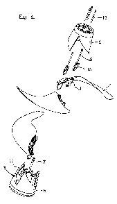
Fig. 1 is an elevated view in the axial direction of an
inventive mixer assembly,
Fig. 2 is a perspective view of a mixer assembly according
to figure 1,
Fig. 3 is an exploded view in part taken from the side of a
preferred embodiment of a mixer assembly,
Fig. 4 is an exploded perspective view of a mixer assembly,
Fig. 5 is a cross sectional side view of a mixer assembly,
Fig. 6 is a perspective view of the hub base and one blade
according to a first embodiment,
Fig. 7 is a side view of a blade according to figure 6,
Fig. 8 is an elevated view in the axial direction of the
blade according to figures 6 and 7,
Fig. 9 is a perspective view of the hub base and one blade
according to a second embodiment corresponding to
figure 6,
Fig. 10 is a side view of the blade according to figure 9
corresponding to figure 7, and
Fig. 11 is a perspective view of a hub base.
Detailed description of preferred embodiments
By way of introduction it should be pointed out that
the inventive propeller assembly include at least mixer
assemblies of mixers and impeller assemblies of propeller
pumps, however, the following detailed description will be
directed towards a mixer assembly of a mixer, but it shall
be realized that everything described below also apply to a
CA 02793358 2012-09-14
WO 2011/115552 PCT/SE2011/050274
6
impeller assembly of a propeller pump, unless otherwise
stated.
In figures 1 and 2 is disclosed an inventive mixer
assembly, generally designated 1, in a mounted condition.
However, it should be pointed out that the mixer assembly 1
is part of a greater mixer (not shown), which besides the
inventive mixer assembly 1 also comprises a motor unit
having an output drive shaft 2, see figure S. Mixer
assemblies are suitable for agitating waste water or the
like, i.e. generating and maintaining a movement within
waste water. Mixer assemblies comprise a hub, generally
designated 3, and at least two blades 4, preferably three
blades. The blades 4 are releasably connected to the hub 3
and extend in general in radial direction in relation to the
hub 3. In a conventional way the blades 4 presents a shape
adapted for the task to agitate a fluid, which shape in
occurring cases entail that each blade 4 presents double
curved main surfaces on its suction side and pressure side,
respectively. In a preferred embodiment each blade 4
receives its shape by molding, and is preferably manu-
factured by aluminum. The hub 3 in its turn presents a free
front end and a rear end, the hub 3 in said rear end being
arranged to be connected to said drive shaft 2 and thereby
being arranged to be driven in rotation about an axially
extending centre axis.
Reference is now made to figures 3 and 4, which disc-
loses the inventive mixer assembly 1 according to a first
embodiment in an elevated exploded view and a perspective
exploded view, respectively, as well as to figure 5 disc-
losing the inventive mixer assembly 1 according to figures 3
and 4 in an elevated sectional view.
In the disclosed embodiment the hub 3 comprises a rear
hub base 5 and a front hub top 6, the hub base 5 being
arranged to be connected to said drive shaft 2. The hub base
5 presents in the disclosed embodiment a rearward opened
hole for receiving the drive shaft 2, whereupon the hub base
CA 02793358 2012-09-14
WO 2011/115552 PCT/SE2011/050274
7
is secured to the end of the drive shaft 2 be means of a
screw 7 axially screwed into the drive shaft 2. Furthermore
the fastening of the hub base 5 to the drive shaft 2 may be
additionally strengthen be means of utilizing a tool cone 8,
5 which is seated in the rearward opened hole and which clamp
the end of the drive shaft 2 concurrently with the
tightening of the screw 7. In the preferred embodiment the
hub base 5 and the hub top 6, respectively, receives their
shape by molding, and are preferably manufactured by
aluminum.
According to the invention the hub 3 comprises a seat,
generally designated 9, for each of said blades 4. Each seat
9 comprises in its turn a first engagement means 10 extend-
ing in the axial direction, and each blade 4 comprises a
second engagement means 11 extending in the axial direction.
Said first engagement means 10 and said second engagement
means 11 are in cooperation arranged to admit axial mutual
displacement of said hub 3 and said each blade 4 during
mounting/demounting of the mixer assembly 1. Furthermore,
the first engagement means 10 and the second engagement
means 11 are arranged to prevent radial mutual displacement
of the hub 3 and each blade 4 when the mixer assembly 1 is
in the mounted condition. Thus, it is essential for the
invention that the blades 4 are applied axially to the hub
3. It should be pointed out that the abutment between each
blade 4 and the hub 3, when the mixer assembly 1 is in the
mounted condition, only occur between the first engagement
means 10 and the second engagement means 11, in order to
prevent over determined positioning of the blades 4 and
accompanying origin of internal strain.
Furthermore, the blades 4 of the mixer assembly, in the
preferred embodiment, are releasably connected to the hub
base 5 by means of axially extending screws 12, or other
suitable fastening means. Each blade 4 comprises preferably
at least one screw 12 that prevents axial mutual displace-
ment/separation of the hub 3 and said each blade 4 when the
CA 02793358 2012-09-14
WO 2011/115552 PCT/SE2011/050274
8
mixer assembly is in the mounted condition. The axial appli-
cation of the screws 12 entail easy and quick mounting/
demounting of the blades 4 to the hub. Furthermore, the hub
top 6 is releasably connected to the hub base 5 by means of
axially extending screws 13, or other suitable fastening
means. The axial application of the screws 13 entail easy
and quick mounting/demounting of the hub top 6 to the hub
base 5. The purpose of the hub top 6 is at first hand to
provide good fluid current properties around the mixer
assembly 1. Furthermore, it is an object of the hub top 6 to
act as a protective device if the attachment means of a
blade 4 breaks and the blade 4 thereby is released from the
hub base 5. In the case when a blade 4 has come loose from
the hub base 5 it will be noticed long before the blade 4 is
thrown away and runs the risk of damaging other equipment of
personnel, due to the fact that the hub top 6 tolerable
keeps the blade 4 in place or at least prevents the blade 4
from flinging away.
In an alternative embodiment (not shown) the mixer
assembly is arranged in such a way that the blades 4 are
attached axially to the hub top 6, which thereafter is
connected to the hub base S. In yet another alternative
embodiment (not shown) the blades 4 are attached axially to
the hub base 5 from the rear direction, whereupon the hub
base 5 is connected to the end of the drive shaft 2 in any
suitable way. It shall be pointed out that in the latter
embodiment no hub top is required. Independently on which
parts being connected to which, it is preferred that said
first engagement means 10 of each seat 9 of the hub 3, and
said second engagement means 11 if each blade 4, are
arranged radially inside the outer envelope surface of the
hub 3 when the mixer assembly is in the mounted condition.
In that way good fluid current properties are obtained and
the engagement means and the attachment means are protected
against the environment in which the mixer assembly is
arranged to work.
CA 02793358 2012-09-14
WO 2011/115552 PCT/SE2011/050274
9
Now reference is made to figure 11. In the preferred
embodiment said first engagement means 10 of each seat 9
comprises at least two recesses, which are mutually
separated in the circumferential direction of the hub 3, and
which are separated by means of an intermediate wall 14.
Preferably said at least two recesses are mutually separated
also in the axial direction of the hub 3. In mixer
assemblies the front recess seen in the rotational direction
of the propeller assembly is located closer to the rear end
of the hub 3 then the rear recess seen in the rotational
direction of the propeller assembly. However, it should be
pointed out that in impeller assemblies there is the
opposite relation, more precisely that the front recess seen
in the rotational direction of the propeller assembly is
located closer to the free end of the hub 3 then the rear
recess seen in the rotational direction of the propeller
assembly. Alternatively the first engagement means 10 is
constituted by an elongated recess extending in the circum-
ferential direction. Preferably each recess provides a
threaded whole 15 in the bottom thereof for receiving above
mentioned screw 12. Furthermore, the second engagement means
11 of each blade 4 comprises in the preferred embodiment at
least two projections, which are mutually separated and
which are arranged to engage said recesses of the first
engagement means 10. By analogy with the description of the
recesses above the mixer assembly is arranged in such a way
that the front projection seen in the rotational direction
of the propeller assembly is located closer to the rear end
of the hub 3 then the rear projection seen in the rotational
direction of the propeller assembly. Furthermore, it should
be pointed out that in mixer assemblies there is the
opposite relation, more precisely that the front projection
seen in the rotational direction of the mixer assembly is
located closer to the free end of the hub 3 then the rear
projection seen in the rotational direction of the mixer
assembly. In the case when the first engagement means 10 is
CA 02793358 2012-09-14
WO 2011/115552 PCT/SE2011/050274
constituted by one recess only, the second engagement means
11 is preferably constituted by one projection only.
It should be pointed out that the opposite relationship
that the first engagement means 10 comprises projections and
5 the second engagement means 11 comprises interacting
recesses may apply without deviating from the invention.
Reference is now specifically made to figures 7 and 8.
It is preferred that each of said at least two projections
of the second engagement means 11 presents the shape of a
10 truncated cone tapering rearward in the axial direction, and
that each of said at least two recesses of the first
engagement means 10 presents complementary shape. The
inclination of outer surface of said at least two project-
tions and the inner surface of said at least two recesses in
relation to an axially extending centre line shall be as
small as possible in order to admit as perpendicular force
transmission as possible between the first engagement means
10 and the second engagement means 11. However, the angle
must be big enough to admit easy axial application and
removal of the blade 4 in relation to the hub 3. Preferably
this angle shall be less than 45 degrees, preferably less
than 20 degrees. In the shown preferred embodiment said
angle is about 10 degrees. Furthermore, the angle shall be
bigger than 5 degrees.
It is preferred that said projection of the second
engagement means 11 is arranged to abut the front projection
of the first engagement means 10 in the rotational direction
as well as in the radial direction, and the rear projection
of the second engagement means 11 is arranged to abut the
rear recess 10 of the first engagement means 10 in the
radial direction only. By this way a well defined position-
ing of each blade 4 is obtained at the same time as the risk
of internal stress of the hub 3 and blade 4 will arise is
minimized. Further, it is preferred that at the abutment
interface there is surface abutment.
CA 02793358 2012-09-14
WO 2011/115552 PCT/SE2011/050274
11
It is yet preferred that each of said at least two
projections of the second engagement means 11 and that each
of said at least two recesses of the first engagement means
presents a polygonal cross section, for instance square
5 shaped. However, it should be pointed out that it is equally
preferred that each of said at least two projections of the
second engagement means 11 and each of said at least two
recesses of the first engagement means 10 present a round
cross section, for instance circular. The advantage of
10 having a round cross section of the front projection and the
front recess is that the engagement between them will not
carry the bending loads acting on the blade 4 in the
rotational direction, instead the bending load on the blade
4 will be carried in interaction with the engagement between
the rear projection and the rear recess. Thereto it is
preferred that each of said at least two projections of the
second engagement means 11 presents a smaller axial
extension than the axial extension of the corresponding
recess of said at least two recesses of the first engagement
means 10, see figure 5. In this way a correct positioning in
the radial direction of the separate blade 4 in relation to
the hub 3 is guaranteed, and the projections of the second
engagement means 11 is not running the risk of touching the
bottom of the recesses of the first engagement means 10.
In order to obtain appropriate screw engagements at the
attachment of the blades 4 to the hub 5, according to the
embodiments according to figures 3-8 a separate distance
sleeve 16 is used together with each projection of the
second engagement means 11. The object of the distance
sleeve 16 is to admit that long enough, and thereby
resilient enough, screws 12 may be used. Due to the fact
that the abutment interface between the first engagement
means 10 and the second engagement means 11 is flat, as
described above, relatively large settlement will take place
when the first engagement means 10 and the second engagement
means 11 have run in, and a long pretensioned screw can
CA 02793358 2012-09-14
WO 2011/115552 PCT/SE2011/050274
12
handle this without coming loose, but a short pretensioned
screw should quickly come loose. The screws 12 will in
principal be loaded in their longitudinal direction only,
due to the fact that the first engagement means 10 and the
second engagement means 11 are arranged to carry mutual
loads in the radial direction and in the rotational
direction between the blades 4 and the hub 5 of the mixer
assembly. In figures 9 and 10 there is shown a preferred
embodiment in which the distance sleeves 16 are fixedly
connected to or most preferably integrated with the second
engagement means 11.
Feasible modifications of the Invention
The invention is not limited only to the embodiments
described above and shown in the drawings, which primarily
have an illustrative and exemplifying purpose. This patent
application is intended to cover all adjustments and
variants of the preferred embodiments described herein, thus
the present invention is defined by the wording of the
appended claims and the equivalents thereof. Thus, the mixer
assembly may be modified in all kinds of ways within the
scope of the appended claims.
It shall also be pointed out that all information
about/concerning terms such as above, below, etc., shall be
interpreted/read having the equipment oriented according to
the figures, having the drawings oriented such that the
references can be properly read. Thus, such terms only
indicates mutual relations in the shown embodiments, which
relations may be changed if the inventive equipment is
provided with another structure/design.
It shall also be pointed out that even thus it is not
explicitly stated that features from a specific embodiment
may be combined with features from another embodiment, the
combination shall be considered obvious, if the combination
is possible.