Note : Les descriptions sont présentées dans la langue officielle dans laquelle elles ont été soumises.
CA 02793793 2012-10-24
1
TITLE OF THE INVENTION
Access doors
FIELD OF THE INVENTION
[0001] The present invention relates to adjustable frames and access doors.
BACKGROUND OF THE INVENTION
[0002] Access doors are used to allow an easy and clean access to walls and
ceilings, floor and roof hatches, for maintenance or repair purposes for
example.
[0003] Conventional access doors comprise a rigid frame secured to a door
by
hinges, and the frame needs to be nailed about an opening in the wall, ceiling
or floor.
[0004] There is still a need in the art for adjustable frames and access
doors.
SUMMARY OF THE INVENTION
[0005] More specifically, in accordance with the present invention, there
is provided
an access door adjustable to an opening having a size defined by a width and a
height, comprising a
frame adjustable to the width and the height of the opening; and a door panel,
of a size at least the
size of the opening, wherein the frame comprises side members and corner
members; each side
member having a section adapted to receive an edge of the opening and
comprising a first part
adapted to lay flat on an outer surface of the edge of the opening and a
second part extending within
the opening, the second part comprising engagement positions along a length
thereof, the
engagement positions being adapted to engage the corner members between a
maximum length for
each side of the frame by using outermost engagement positions along the
length of the side
member on each side of the side member and a minimum length for each side of
the frame by using
CA 02793793 2012-10-24
2
innermost engagement positions on each side of the side member, depending on
the size of the
opening, the frame receiving the door panel for closing the opening.
[0006] There is further provided a method for closing an opening having
relatively
straight edges in a panel, comprising; a) aligning a first side member and a
first corner member, the
side member comprising a first part and a second part, the second part
comprising engagement
positions; b) engaging one of the engagement positions of the side member with
the corner member
based on the size of the opening, and snapping the corner member and the side
member together; c)
repeating steps a) and b) with a second, third and fourth side members and a
second, third and
fourth corner members to form a frame of the size of the opening; d)
positioning the frame within the
opening, the corners members fitting with the corners of the opening, the
first part of each side
member sitting on an outer surface of the edge of the opening, and the second
part of each side
member extending into the opening; e) aligning at least one glide provided on
an inner surface of a
door panel with a notch of at least one corner member based on the size of the
frame and engaging
a distal end of the glide in the notch; and f) moving the door panel against
the frame.
[0007] There is further provided a frame for an opening, comprising sides
having a
section adapted to receive an edge of the opening and comprising a first part
adapted to lay flat on
an outer surface of the edge of the opening, and a second part extending
within the opening; the
second part comprising positioning slots; and corners, each corner comprising
two arms at a
substantially right angle, each arm comprising a positioning pin adapted to
engage a positioning slot
of a side; wherein the sides are connected two by two by the corners by
selecting a positioning slot of
the sides for engagement by the positioning pin based on a size of the
opening.
[0008] There is further provided a method for adjusting a frame about an
opening,
comprising: a) aligning a first side member and a first corner member, the
side member comprising a
first part and a second part, the second part comprising positioning slots;
and the corner member
comprising two arms each having a positioning pin; b) engaging a positioning
slot of the side member
with the positioning pin of an arm of the corner member based on the size of
the opening, and
snapping the corner member and the side member together; and c) repeating
steps a) and b) with a
CA 02793793 2012-10-24
3
second, third and fourth side members and a second, third and fourth corner
members to form a
frame.
[0009] Other objects, advantages and features of the present invention will
become
more apparent upon reading of the following non-restrictive description of
specific embodiments
thereof, given by way of example only with reference to the accompanying
drawings.
BRIEF DESCRIPTION OF THE DRAWINGS
[0010] In the appended drawings:
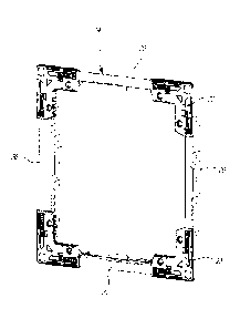
[0011] Figures 1 show a) a door panel, b) corners, c) sides of a frame;
Figure 1d
shows an assembled frame according to an embodiment of an aspect of the
present invention;
[0012] Figure 2 shows an opening in a wall, ceiling or floor panel;
[0013] Figures 3 show a) a perspective view, b) a side view, and c) a cross
section
view of a side member of a frame according to an embodiment of an aspect of
the present invention;
[0014] Figures 4 show a) a perspective view, b) a side view, and c) a cross
section
view of a side member of a frame according to an embodiment of an aspect of
the present invention;
[0015] Figures 5 show a) a perspective view, b) a side view, and c) a cross
section
view of a side member of a frame according to an embodiment of an aspect of
the present invention;
[0016] Figures 6 show a) a perspective view, b) a side view, and c) a cross
section
view of a side member of a frame according to an embodiment of an aspect of
the present invention;
[0017] Figures 7 show a) a perspective view of the inner surface, b) the
outer
CA 02793793 2012-10-24
p
4
surface, and c) a side view, of a corner member of a frame according to an
embodiment of an aspect
of the present invention;
[0018] Figures 8 show) a perspective view, b) a top view of a lock
according to an
embodiment of an aspect of the present invention;
[0019] Figures 9 show a set of side members according to an embodiment of
an
aspect of the present invention;
[0020] Figures 10 a) - f) show steps for assembling a frame according to
an
embodiment of an aspect of the present invention;
[0021] Figures 11 a) - c) show steps for assembling a locking mechanism
onto a door
panel of an access door according to an embodiment of an aspect of the present
invention;
[0022] Figures 12 a)- d) ) show steps for installation of an assembled
frame in an
opening according to an embodiment of an aspect of the present invention;
[0023] Figure 13 a) - e) show steps for installing a door panel into an
assembled
frame according to an embodiment of an aspect of the present invention; and
[0024] Figures 14 show a) a perspective view and b) a side view of a glide
for a door
panel according to an embodiment of an aspect of the present invention.
DESCRIPTION OF EMBODIMENTS OF THE INVENTION
[0025] According to an embodiment of an aspect of the present invention,
an
adjustable frame 14, shown assembled in Figure 1 d, comprises side members 20
(see Figure 1c)
connected two by two by corner members 22 (see Figure lb). The side members 20
may be metallic
CA 02793793 2012-10-24
5
members and the corners 22 plastic members for example. Other materials may be
used.
[0026] The side members 20 are rigid members which, by interaction with
the corners
22, adjust to a desired frame size. In the case of a frame for an opening (C)
in a panel (W) as shown
in Figure 2 for example, the corners members 22 adapt to the corners of the
opening (C), and the
side members 20 adjust to the length and thickness of the edges of the opening
(C) as will be
discussed hereinbelow.
[0027] Figures 3-6 illustrate embodiments of side members 20 having a L
section
(see Figures 3c, 4c, 5c, and 6c), and comprising a first part 22a adapted to
sit flat on the outer
surface, i.e. the visible surface, of the edge of an opening, and a second
part 22b adapted to extend
within the opening and comprising foldable tabs 24 and positioning slots 27
along its length. The L
section provides protecting the material on the edge on the perimeter of the
opening (C), with the
tabs 24 being foldable inside the opening against the inner surface, i.e.
behind the wall, ceiling or
floor panel, of the edge of the opening thereby maintaining the side member 20
about the opening,
as will be described hereinbelow. The positioning slots 27 provide different
positions for securing the
side member to two corner members on each side thereof, as will be described
hereinbelow,
between a maximum length for a side by using the outermost positioning slots
27o along the length
of the side member on each side of the side member, for engagement with the
corner members, and
a minimum length for a side by using the inner most positioning slots 27i on
each side of the side
member, for engagement with the corner members.
[0028] In Figures 7, a corner member 22 is shown as a symmetric element
relative to
an axis (X) shown in Figure 7b, comprising two arms at a substantially right
angle, each arm adapted
to connect with an extremity of a side member. Each arm comprises a
positioning pin 21 on an inner
surface, i.e. the surface directed towards the opening (best seen Figures 7a
and 7c) and notches 40
on the inner edge of each arm (best seen in Figure 7b). In the illustration of
Figure 7a, each
positioning pin 21 extends perpendicularly from the inner surface of the
corner member, at a distance
from the outer edge of the corner member occupied by a surface 23 adapted to
slidingly receive a
part 22a of a side member 20 as will be discussed hereinbelow. Moreover, the
positioning pin 21
CA 02793793 2012-10-24
6
may be provided with a detent 29 for easy access to the positioning pin 21,
once the part 22b of a
side member 20 is snapped thereto, as discussed hereinbelow. It may also
comprise an embedded
magnet 42, or other element adapted to retain a door panel, as will be
discussed hereinbelow.
Apertures 37, or other feature for securing a cable, may further be provided
on each arm, as will be
discussed hereinbelow.
[0029] The positioning pin 21 of each arm of a corner member 22 is adapted
to
receive a positioning slot 27 of a respective side member 20 to adapt to the
size of the opening (C)
as will be described hereinbelow in relation to Figures 9 and 10 for example.
[0030] The side member 20 may also comprise a locking slot 26. In Figures 3
and 4,
the locking slot 26 is shown covered by a tab 25, while in Figures 5 and 6 the
locking slot 26 is
shown with the tab 25 folded away, so that the locking slot 26 is adapted to
receive a lock 30 as will
be described hereinbelow in relation to Figures 11.
[0031] An access door basically comprises a frame (Figure 1d) supporting a
door
panel (Figure la) used to cover an opening (C), into a panel (W), such as a
wall, a ceiling or a floor
panel for example (Figure 2). The opening (C) has a width wc and a height hc.
[0032] The door panel 12 may be metallic for example, or in other rigid
material, such
as wood, board or plastic for example. The door panel is of a generally
rectangular or square shape,
with a width wp and a height hp, of a size at least the size of the opening to
be covered: i.e. wp is at
least equal to wc and hp is at least equal to hc.
[0033] According to an embodiment of the present invention, the door panel
12
comprises at least one glide, two glides 38 being shown in Figures 11 and 13
for example, on its
inner surface, i.e. its surface intended to be facing the opening. As shown in
Figures 14, a glide 38
comprises a part 41 rising from the inner surface of the door panel 12 and
having a distal end 43. As
will be described hereinbelow in relation to Figures 13, a glide 38 ensures
centering of the door panel
12 relative to the frame 14 by engaging a corner member. Depending on the size
of the frame 14, the
CA 02793793 2012-10-24
7
distal end 43 of the glide 38 engages a corresponding notch 40 of a corner
member 22, thereby
securing the door panel 12 to the frame 14, and stabilizing the access door
14, once installed. The
glide 38 may also comprise an attachment for a cable, such as an opening 39,
shown in Figures 14.
[0034] A locking mechanism may be provided, by positioning a lock 30 on the
inner
surface of the door panel 12. The lock 30 shown in Figures 8 comprise a slot
33 at a distal end
thereof and a series of holes 34 along its length allowing different
locations, depending on the size of
the frame 14, for securing the lock 30 to the door panel 12 by its proximal
end 35 so that the distal
end 33 can engage the locking slot 26 of a side member 22, as will be
described hereinbelow in
relation to Figures 11.
[0035] For installation, no framing or construction is necessary provided
the edges of
the wall opening (C) are relatively straight, and square to each other for
best fit, otherwise the door
may be out of square when installed. The edges of the opening should also be
square to surrounding
walls, ceilings or floors to ensure that the frame and/or the access door look
level when finished.
[0036] In an embodiment of the present invention, the frame 14 can be
selected to fit
the size hc and wc of the opening (C), in increments corresponding to the
positions of the positioning
slots 27 of the side members 22, for example in increments of 3/8" of an inch,
between a minimum
size and a maximum size for a given model depending on the positions of the
connection between
side members and corner members as described hereinabove (see Figures 9), in
width and/or
height. The opening (C) can be square or rectangular in shape.
[0037] The panel door 12 can be painted or wallpapered to match the color
or finish
of the wall, ceiling or floor panel.
[0038] For assembling the frame 14, a side member 20 is aligned with an arm
of a
corner member 22, for example by sliding on the surface 23 in the embodiment
illustrated in Figures
7 (see arrow (B) in Figure 7a), based on a required sizing (see Figure 10d) so
as to engage the
positioning pin 21 on this arm of the corner member 22 into one of the
positioning slots 27 of the side
CA 02793793 2012-10-24
8
member 22 (Figures 10a-10b), and the corner member 22 and the side member 20
are then snapped
together. A clicking sound indicates that they are connected. Once connected
the two members can
be easily disconnected, if necessary, for example by action with a finger on
the detent 29 of the
positioning pin 21 as illustrated in Figures 7, and reconnected (see Figure
10c). The remaining
corners and sides are connected in the same way, so as to end up with a full
frame 14 of a size
adjusted to the size of the opening to be covered (see Figure 1b).
[0039] A safety cable 36 may be attached to at least one corner 22, by
inserting the
cable 36 through an opening 37 in an arm of the corner member 22 for example
(Figures 10e-10f).
[0040] If using a locking mechanism, the door panel 12 is laid with its
outer surface
down and the frame 14 is put squarely into position (see Figures 11) about its
inner surface, in order
to determine which hole 34 of the lock 30 is the correct distance for the
proximal end 35 thereof to be
fastened to the panel 12, so that the distal end 33 of the lock 30 is able to
engage the frame 14 (see
Figure 10c). Then the lock 30 is fastened to the panel 12 with a screw for
example through the
corresponding hole 34 in the proximal end 35 (see Figure 11b), so that it may
rotate, about the screw
position, from a locking position, in which the distal end 33 of the lock 30
engages the frame 14, to an
unlocking position, in which the distal end 33 of the lock 30 is not connected
to the frame 14 (see
arrow A in Figure 11b).
[0041] Then, as shown in Figures 12, with or without a locking mechanism,
the frame
14 is positioned within the opening (C) (Figure 12a) and tabs 24 are folded
behind the wall, ceiling or
floor panel, to lock the frame 14 into place within the opening (Figure 12b).
If there is an obstacle (0)
in the opening (C), tabs 24 may be bent outwards as needed (Figure 12d). If
there is a solid structure
(S) present, the frame 14 can be screwed in to it through holes of the tabs 24
for example (Figure
12c).
[0042] To close the door, each safety cable 36 secured to a corner member
22 is
connected to a door glide 38 (Figure 13a-13b). The glides 38 of the door panel
12 are aligned to
respective notches 40 on the corner members 22 depending on the size of the
frame (Figure 13c)
CA 02793793 2012-10-24
9
and engaged therein (Figure 13d). Then the door panel is moved against the
frame, thereby closing
the access door. Figures 13d and 13e show views from inside of the wall, floor
or ceiling once the
door is thus closed.
[0043] In case of a metallic door panel, magnets 42 embedded in the corner
members 22 as illustrated for example in Figures 7 may further retain the door
panel 12 in place for
better stability. Other retaining elements between the frame members and the
door panel may be
contemplated depending on the different materials used and on the different
requirements of a
specific application.
[0044] The access door is now installed. It is a removable door which gives
access to
the interior of the panel.
[0045] For specific applications, such as an access door in a ceiling panel
for
example, securing means such as cables 36 allow further securing the access
door once in place by
catching the access door should it become dislodged from its opening for
example.
[0046] To open the door, the door panel 12 is pulled outward, by inserting
a fingernail
or a small flat screwdriver into a corner of the door panel, which may be
identified beforehand for
simplicity purposes, since corners of the door panel located away from where
the door panel is
connected to a corner member of the frame by a glide on the inner side
thereof, as described
hereinabove, offer easier opening.
[0047] In case a locking mechanism as described hereinabove is used, a
slotted or
flat head screw driver may be used to lock or unlock the access door from the
outside, to disengage
the distal end 33 of the lock 30 from the frame 14 on the inner surface of the
door panel inside the
opening, as described hereinabove.
[0048] As people in the art will appreciate, the present access door is
installed
CA 02793793 2012-10-24
10
quickly, without specific tools, and easily by virtually anyone regardless of
skill level.
[0049] The present access door is adjustable and may apply for a range of
sizes. In
the examples illustrated herein for way of examples, there are five different
side dimensions, with five
possible adjustments by an increment of 3/8. On the vertical and horizontal
axes, for a given size of
side members, the possible positions for an 8X 9.5 -inch frame are: 8, 8.375,
8.75, 9,125 and 9.5
inches (see embodiments illustrated in Figures 9).
[0050] The invention was described hereinabove using positioning slots in
sides of
the frame and positioning pins in corners of the frame for adjustability of
the size of the frame. Other
controllable and reversible engagement mechanisms between sides and corners
may be
contemplated. Also, the sides, or the corners, may comprise telescopic parts,
which length can be
adjusted prior to, or after, connection between sides and corners.
[0051] As people in the art will now be in a position to appreciate, the
present
adjustable frame and access door allow overcoming obstacles that may be
encountered in walls,
ceilings or floors, such as, for example, posts and beams and pipes, and
generally any space
constraints. Moreover, the present adjustable frame allows accommodating a
range of panel
thickness.
[0052] Although the present invention has been described hereinabove by way
of
embodiments thereof, it may be modified, without departing from the nature and
teachings of the
subject invention as recited herein.