Sélection de la langue

Search

Sommaire du brevet 2793896 

Énoncé de désistement de responsabilité concernant l'information provenant de tiers

Une partie des informations de ce site Web a été fournie par des sources externes. Le gouvernement du Canada n'assume aucune responsabilité concernant la précision, l'actualité ou la fiabilité des informations fournies par les sources externes. Les utilisateurs qui désirent employer cette information devraient consulter directement la source des informations. Le contenu fourni par les sources externes n'est pas assujetti aux exigences sur les langues officielles, la protection des renseignements personnels et l'accessibilité.

Disponibilité de l'Abrégé et des Revendications

L'apparition de différences dans le texte et l'image des Revendications et de l'Abrégé dépend du moment auquel le document est publié. Les textes des Revendications et de l'Abrégé sont affichés :

  • lorsque la demande peut être examinée par le public;
  • lorsque le brevet est émis (délivrance).
(12) Brevet: (11) CA 2793896
(54) Titre français: PROCEDE DE CODAGE D'UNE SERRURE ET EBAUCHE POUR LA MISE EN OEUVRE DU PROCEDE
(54) Titre anglais: METHOD FOR CODING A LOCK AND BLANK FOR PERFORMING SAID METHOD
Statut: Accordé et délivré
Données bibliographiques
(51) Classification internationale des brevets (CIB):
  • E05B 35/00 (2006.01)
  • B23P 15/00 (2006.01)
  • H01H 27/00 (2006.01)
(72) Inventeurs :
  • HAAKE, ANDRE (Allemagne)
  • HAAKE, PATRICK (Allemagne)
  • HAAKE, OLIVER (Allemagne)
(73) Titulaires :
  • ANDRE HAAKE
  • PATRICK HAAKE
  • OLIVER HAAKE
(71) Demandeurs :
  • ANDRE HAAKE (Allemagne)
  • PATRICK HAAKE (Allemagne)
  • OLIVER HAAKE (Allemagne)
(74) Agent: SMART & BIGGAR LP
(74) Co-agent:
(45) Délivré: 2015-05-12
(86) Date de dépôt PCT: 2011-09-27
(87) Mise à la disponibilité du public: 2012-05-18
Requête d'examen: 2012-10-04
Licence disponible: S.O.
Cédé au domaine public: S.O.
(25) Langue des documents déposés: Anglais

Traité de coopération en matière de brevets (PCT): Oui
(86) Numéro de la demande PCT: PCT/DE2011/075235
(87) Numéro de publication internationale PCT: DE2011075235
(85) Entrée nationale: 2012-09-20

(30) Données de priorité de la demande:
Numéro de la demande Pays / territoire Date
10 2010 038 105.5 (Allemagne) 2010-10-11

Abrégés

Abrégé français

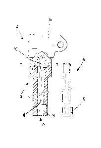
L'invention concerne un procédé de codage d'une clé et d'un piston de fermeture pour une serrure d'un système de verrouillage. Selon le procédé, une ébauche est séparée en deux parties par une découpe de séparation réalisée perpendiculairement à l'axe longitudinal et en direction de l'axe longitudinal de l'ébauche, et les deux parties sont ensuite façonnées pour former la clé ou le piston de fermeture ou reliées à la clé et au piston de fermeture en tant que plaques de codage, la découpe de séparation pouvant être réalisée perpendiculairement à l'axe longitudinal et simultanément en direction de l'axe longitudinal de l'ébauche.


Abrégé anglais

The invention relates to a method for coding a key and a female lock part for a lock for a locking system, wherein a blank is separated into two parts by a separating cut guided perpendicularly to the longitudinal axis and in the direction of the longitudinal axis of the blank and the two parts are then post-processed to form the key and the female lock part or are connected to the key and the female lock part as coding disks, wherein the separating cut can be guided perpendicularly to the longitudinal axis and at the same time in the direction of the longitudinal axis of the blank.

Revendications

Note : Les revendications sont présentées dans la langue officielle dans laquelle elles ont été soumises.


Claims:
1. A method for coding a key part and a female lock part for a lock for a
locking system, wherein a
blank is separated into two parts by a separating cut guided transversely to
the longitudinal axis and
in the direction of the longitudinal axis of the blank and that the two parts
are subsequently worked
to the key and to the female lock part.
2. A method for coding a key part and a female lock part for a lock for a
locking system, wherein a
blank is separated into two parts by a separating cut guided transversely to
the longitudinal axis and
in the direction of the longitudinal axis of the blank and that the two parts
are subsequently
connected as coding disks to the key and to the female lock part.
3. The method according to claim 1 or 2, wherein the separating cut is guided
transversely to the
longitudinal axis and simultaneously in the direction of the longitudinal axis
of the blank.
4. The method according to claim 1 or 2, wherein the blank is constructed like
a bolt.
5. The method according to claim 1 or 2, wherein a key bolt with key bit which
bolt traverses the
female lock part is inserted into the key or into the female lock part.
6. The method according to claim 1 or 2, wherein a laser separating method is
used as separating
method.
7. The method according to claim 1, 2 or 3, wherein a water-jet separating
method is used as
separating method.
8. The method according to claim 1, 2 or 3, wherein a blank of metal is used.
9. The method according to claim 1, 2 or 3, wherein a blank of plastic is
used.
10. The method according to claim 1, 2 or 3, wherein a blank of a high-quality
part is used.
11. The method according to claim 1, 2 or 3, wherein a blank of a rod material
is used.
7

Description

Note : Les descriptions sont présentées dans la langue officielle dans laquelle elles ont été soumises.


CA 02793896 2012-09-20
Method for Coding a Lock and Blank for Performing Said Method
Specification
The invention relates to a method for coding a key and a female lock part for
a lock for a locking
system and to the blank used for carrying out said method.
For example, in a key transfer system the female lock part is built into the
lock of the key
transfer system and is therefore, e.g., an integral component, whereby a key
is required to actuate
the lock and with it the female lock part. The individual locks have a coding
between the female
lock part and the key so that the actuation of the actual lock is only
possible with the coinciding
coding. In the normal case the key engages into the female lock part of the
lock and therefore
forms a positive unit. The female lock part itself cooperates, e.g., with a
blocking device of the
tumbler device or via an integrated square or the like, e.g., with an
electrical switch.
In the prior art (see fig. 1 of the attached drawings) the coding consists of
a combination of pins
and bores. The key comprises a plurality of bores in a certain arrangement and
the female lock
part is provided with the same number of pins also in the same arrangement as
in the female lock
part which can engage upon a coinciding coding into the bores of the key. The
key can then be
introduced so far that the lock can be actuated. If the hole picture and the
pin picture do not
correspond an actuation of the key and therefore of the lock is not possible.
The providing of milled-out letters or combinations of letters instead of pins
and bores is also
known in the prior art. Milled or cast contours are also used.
It is characteristic for the prior art and the codings known in it that they
must be manufactured
separately from each other for keys and female lock parts. That means that the
key is coded by
working, e.g., manufacturing the bores and the female locking part is adapted
in a corresponding
manner by working, namely by the manufacturing of bores and pressing in the
pins.
It is obvious that the manufacture of these known codings is expensive and
that the number of
codings is limited.
1

CA 02793896 2014-04-30
Exemplary of a blank that is, e.g., shaped like a bolt is used that is divided
into two parts by a
separating cut guided transversally to the longitudinal axis and in the
direction of the longitudinal
axis of the blank, whereby the two parts are subsequently worked to the key
and to the female
locking part or are connected as coding disks to the key and to the female
locking part.
The separation plane may be achieved by the separating cut or the separating
method between the
two parts of the blank and may automatically form the coding.
It is possible to proceed in such a manner here that the separating method is
guided transversely to
the longitudinal axis and at the same time in the direction of the
longitudinal axis so that, therefore,
a corrugated separating plane is achieved.
It is possible in the same manner to provide a parallel or a radial separating
cut.
In sum, it can therefore be determined that in particular the contour, the
alignment of the contour
and the radial alignment of the contour to the longitudinal axis of the blank
result in the maximally
possible number of codings.
The coding disks achieved in this manner may be connected to the actual key
and to the female
lock part and the achieved and coded female lock part may be built into the
lock.
It is also possible, instead of providing the coding on the key and on the
female lock part, to use a
separate structural part from which two disks are then created by the
separating cut creating the
coding, from which the one disk can be connected to the key part and the other
disk can be
connected to the female lock part.
If the coding is provided on the key and on the female lock part, the coding
of the key and of the
female lock part may take place before the assembly of the locking device.
This means that the
manufacturing may be made on a made-to-order basis, which makes the
manufacture of this
structural part very time-consuming.
However, if the coding is provided on two coding disks, these coding disks can
be connected to the
key and to the female locking part so that there is the possibility of
providing the connection of the
coding disks as the last work step in the manufacture of the components. It is
then possible to
manufacture and prefabricate the structural parts of the lock, i.e., the key,
the locking device, the
2

CA 02793896 2014-04-30
tumbler device, the lock, etc. and to manufacture the coding disks only in the
case of an order,
which disks are then connected to a female lock part and to a key.
The connection of the coding disks to the key and to the female lock part can
take place in very
different ways, namely, positively, in a material-fit manner, and non-
positively. A press
connection, rivet connection, screw connection or clips method can be used
here and means such as
guard bolts or the like can be used.
As disclosed, a key bolt with key bit and traversing the female lock part is
inserted into the key so
that the key is secured against being pulled out axially in the actuated
state, for example, in the
rotated state.
The blank can be formed of metal or of plastic and can be, for example, a high-
quality part or a
cylindrical or polygonal rod material.
The separating method can be, for example, a laser separating method or a
water-jet separating
method but the invention is in no way limited to them.
Thus, it can be determined in sum that the coding of key and female lock part
or a blank that is
inserted between the key and the female lock part can take place in one work
step on a starting
structural part. Tolerances no longer have to be taken into account since both
codings always fit
together since they are manufactured from one part.
The novel method makes possible a very high number of codings and the codings
form parts that
consist of one material so that corrosions are therefore largely avoided.
The manufacture of the coding is also possible in the case of materials that
are difficult to work
mechanically and on account of the separating method selected an economical
manufacture is
possible.
In one aspect, the present invention provides a method for coding a key part
and a female lock part
for a lock for a locking system, wherein a blank is separated into two parts
by a separating cut
guided transversely to the longitudinal axis and in the direction of the
longitudinal axis of the blank
and that the two parts are subsequently worked to the key and to the female
lock part.
3

CA 02793896 2014-04-30
In another aspect, the present invention provides a method for coding a key
part and a female lock
part for a lock for a locking system, wherein a blank is separated into two
parts by a separating cut
guided transversely to the longitudinal axis and in the direction of the
longitudinal axis of the blank
and that the two parts are subsequently connected as coding disks to the key
and to the female lock
part.
Finally, it should be pointed out that neither cuttings nor waste accumulate
in the novel method.
3a

CA 02793896 2012-09-20
=
An exemplary embodiment of the invention is explained in the following using
the drawings.
In the drawings
Fig. 1 shows the state of the art,
Fig. 2 shows a blank
Fig. 3 shows the two individual parts manufactured from the blank by a
separating method,
Fig. 4 shows different coding possibilities,
Fig. 5 shows a key and female lock part manufactured in accordance with the
method of the
invention, and
Fig. 6 shows a view in the direction of the arrow A onto the arrangement
according to fig. 5, and
Fig. 7 shows the use of coding disks.
Fig. 1, that shows the state of the art, shows a key A and a female lock part
B, which key A is
provided with bores into which pins are arranged on the upper side of the
female lock part B can
engage. Therefore, the coding is achieved by a certain arrangement of the
position of the pins
and of the bores. It is obvious that a working is required in which the key or
the female lock part
is provided with appropriate bores and the female lock part and that the
female lock part is
provided with the corresponding pins inserted and pressed into bores. This
manner of working
has the disadvantage that tolerances are created, that under certain
circumstances different
materials are used, in particular for the selection of the pins inserted into
the female lock part B,
and that the method is expensive.
Fig. 2 shows a blank 1 that is formed, e.g., by a cylindrical bolt and serves
as the start for the
manufacture of a female lock part 3 and of a key 2.
According to fig. 3 the blank 1 is divided by a separating method into two
parts, which two parts
form the key 2 and the female lock part 3, and the separating method itself
will form the codings.
The separating method can be carried out in such a manner that the separating
plane T-T takes
place transversely to the longitudinal axis of the blank 1 and in the
direction of the longitudinal
axis L-L of the blank 1, as is shown in fig. 4, or the separating cut is made
radially in a stellate
4

CA 02793896 2012-09-20
shape so that the blank 1 is separated in the form of a piece of cake. In this
method the middle
axis of the workpiece must be focused and the female lock part 3 must
necessarily be provided
with a middle bore 7 as outlet.
As can be seen, angular or rounded contours result from the selection of the
separating method,
whereby the angular contours are very well suited for transmitting the torque
between the key
and the female lock part. The rounded contours have the advantage that they
have less of a
tendency to become dirty and the danger of injuries is less.
The use of the rounded contours has the disadvantage that a functional element
for transferring
the torque from key 2 to female lock part 3 is additionally required. For
example, the key bolt 4
with key bit 5 recognizable in fig. 5 is suited for this.
The angular contours therefore have the advantage that they create the coding
as well as that they
can transmit the necessary torque.
According to fig. 5 and 6 a ready-to-use structural part can be recognized
that consists of a key
grip 6 that is manufactured with the key 2 from the same material or is
permanently anchored on
the key 2. A separating plane T- T is present between the key 2 and the actual
female lock part 3,
which plane comprises the coding and that is manufactured according to one of
the previously
described methods. Furthermore, the key bolt 4 is inserted into the key 2 into
a downwardly open
bore 10, which key bolt has a key bit 5, which key bit 5 engages into a
corresponding groove 8 of
the female lock part 3 so that there is a very rotation-proof connection for
transmitting the torque
between the key 2 and the female lock part 3. Furthermore, the bit 5 engages
into the recess 9 by
rotation, so that the key bolt 4 is securely held.
Fig. 7 shows the possible embodiment with coding disks that are connected to
the key on the one
hand and to the female lock part on the other hand in a method belonging to
the prior art, e.g., by
a clips method, press connection, rivet connection, screw connection or by
guard rings.
In fig. 7 the actual key is designated with 6a, the coding disk associated
with this key 6a with 11
and the female lock part with 3a with the coding disk 12 associated with it.
The female lock part
3a, the coding disks 11 and 12 as well as the actual key 6a have a through
bore 10a into which a
key bolt 4a can be inserted as previously described.

CA 02793896 2012-09-20
This embodiment with coding disks 11 and 12 has the advantage that there is
now the possibility
that the components forming the closing device, namely, the key, locking
device, tumbler device,
lock elements or switching device can be prefabricated, that the coding disks
11 and 12 are not
manufactured until there is an order and that they then must be connected to
the other
components. Therefore, in the case of an order only the coding is produced
while the other parts
can be prefabricated.
6

Dessin représentatif
Une figure unique qui représente un dessin illustrant l'invention.
États administratifs

2024-08-01 : Dans le cadre de la transition vers les Brevets de nouvelle génération (BNG), la base de données sur les brevets canadiens (BDBC) contient désormais un Historique d'événement plus détaillé, qui reproduit le Journal des événements de notre nouvelle solution interne.

Veuillez noter que les événements débutant par « Inactive : » se réfèrent à des événements qui ne sont plus utilisés dans notre nouvelle solution interne.

Pour une meilleure compréhension de l'état de la demande ou brevet qui figure sur cette page, la rubrique Mise en garde , et les descriptions de Brevet , Historique d'événement , Taxes périodiques et Historique des paiements devraient être consultées.

Historique d'événement

Description Date
Représentant commun nommé 2019-10-30
Requête pour le changement d'adresse ou de mode de correspondance reçue 2018-03-28
Accordé par délivrance 2015-05-12
Inactive : Page couverture publiée 2015-05-11
Inactive : Taxe finale reçue 2015-02-12
Préoctroi 2015-02-12
Un avis d'acceptation est envoyé 2014-08-27
Lettre envoyée 2014-08-27
Un avis d'acceptation est envoyé 2014-08-27
Requête visant le maintien en état reçue 2014-08-13
Inactive : Q2 réussi 2014-06-09
Inactive : Approuvée aux fins d'acceptation (AFA) 2014-06-09
Modification reçue - modification volontaire 2014-04-30
Inactive : Dem. de l'examinateur par.30(2) Règles 2013-10-31
Inactive : Rapport - Aucun CQ 2013-10-18
Requête visant le maintien en état reçue 2013-07-05
Inactive : Page couverture publiée 2012-11-20
Lettre envoyée 2012-11-16
Inactive : CIB attribuée 2012-11-14
Demande reçue - PCT 2012-11-14
Inactive : CIB en 1re position 2012-11-14
Inactive : Notice - Entrée phase nat. - Pas de RE 2012-11-14
Inactive : CIB attribuée 2012-11-14
Toutes les exigences pour l'examen - jugée conforme 2012-10-04
Exigences pour une requête d'examen - jugée conforme 2012-10-04
Requête d'examen reçue 2012-10-04
Exigences pour l'entrée dans la phase nationale - jugée conforme 2012-09-20
Demande publiée (accessible au public) 2012-05-18

Historique d'abandonnement

Il n'y a pas d'historique d'abandonnement

Taxes périodiques

Le dernier paiement a été reçu le 2014-08-13

Avis : Si le paiement en totalité n'a pas été reçu au plus tard à la date indiquée, une taxe supplémentaire peut être imposée, soit une des taxes suivantes :

  • taxe de rétablissement ;
  • taxe pour paiement en souffrance ; ou
  • taxe additionnelle pour le renversement d'une péremption réputée.

Les taxes sur les brevets sont ajustées au 1er janvier de chaque année. Les montants ci-dessus sont les montants actuels s'ils sont reçus au plus tard le 31 décembre de l'année en cours.
Veuillez vous référer à la page web des taxes sur les brevets de l'OPIC pour voir tous les montants actuels des taxes.

Historique des taxes

Type de taxes Anniversaire Échéance Date payée
Taxe nationale de base - générale 2012-09-20
Requête d'examen - générale 2012-10-04
TM (demande, 2e anniv.) - générale 02 2013-09-27 2013-07-05
TM (demande, 3e anniv.) - générale 03 2014-09-29 2014-08-13
Taxe finale - générale 2015-02-12
TM (brevet, 4e anniv.) - générale 2015-09-28 2015-09-15
TM (brevet, 5e anniv.) - générale 2016-09-27 2016-09-15
TM (brevet, 6e anniv.) - générale 2017-09-27 2017-09-13
TM (brevet, 7e anniv.) - générale 2018-09-27 2018-09-11
TM (brevet, 8e anniv.) - générale 2019-09-27 2019-09-16
TM (brevet, 9e anniv.) - générale 2020-09-28 2020-09-17
TM (brevet, 10e anniv.) - générale 2021-09-27 2021-09-20
TM (brevet, 11e anniv.) - générale 2022-09-27 2022-09-15
TM (brevet, 12e anniv.) - générale 2023-09-27 2023-09-13
Titulaires au dossier

Les titulaires actuels et antérieures au dossier sont affichés en ordre alphabétique.

Titulaires actuels au dossier
ANDRE HAAKE
PATRICK HAAKE
OLIVER HAAKE
Titulaires antérieures au dossier
S.O.
Les propriétaires antérieurs qui ne figurent pas dans la liste des « Propriétaires au dossier » apparaîtront dans d'autres documents au dossier.
Documents

Pour visionner les fichiers sélectionnés, entrer le code reCAPTCHA :


Pour visualiser une image, cliquer sur un lien dans la colonne description du document. Pour télécharger l'image (les images), cliquer l'une ou plusieurs cases à cocher dans la première colonne et ensuite cliquer sur le bouton "Télécharger sélection en format PDF (archive Zip)" ou le bouton "Télécharger sélection (en un fichier PDF fusionné)".

Liste des documents de brevet publiés et non publiés sur la BDBC .

Si vous avez des difficultés à accéder au contenu, veuillez communiquer avec le Centre de services à la clientèle au 1-866-997-1936, ou envoyer un courriel au Centre de service à la clientèle de l'OPIC.


Description du
Document 
Date
(aaaa-mm-jj) 
Nombre de pages   Taille de l'image (Ko) 
Description 2012-09-19 6 258
Revendications 2012-09-19 2 47
Abrégé 2012-09-19 1 15
Dessins 2012-09-19 4 68
Dessin représentatif 2012-11-14 1 8
Description 2014-04-29 7 269
Revendications 2014-04-29 1 38
Dessin représentatif 2015-04-21 1 6
Accusé de réception de la requête d'examen 2012-11-15 1 175
Avis d'entree dans la phase nationale 2012-11-13 1 193
Rappel de taxe de maintien due 2013-05-27 1 114
Avis du commissaire - Demande jugée acceptable 2014-08-26 1 161
PCT 2012-09-19 5 158
Taxes 2013-07-04 2 83
Taxes 2014-08-12 2 78
Correspondance 2015-02-11 2 73