Sélection de la langue

Search

Sommaire du brevet 2794548 

Énoncé de désistement de responsabilité concernant l'information provenant de tiers

Une partie des informations de ce site Web a été fournie par des sources externes. Le gouvernement du Canada n'assume aucune responsabilité concernant la précision, l'actualité ou la fiabilité des informations fournies par les sources externes. Les utilisateurs qui désirent employer cette information devraient consulter directement la source des informations. Le contenu fourni par les sources externes n'est pas assujetti aux exigences sur les langues officielles, la protection des renseignements personnels et l'accessibilité.

Disponibilité de l'Abrégé et des Revendications

L'apparition de différences dans le texte et l'image des Revendications et de l'Abrégé dépend du moment auquel le document est publié. Les textes des Revendications et de l'Abrégé sont affichés :

  • lorsque la demande peut être examinée par le public;
  • lorsque le brevet est émis (délivrance).
(12) Demande de brevet: (11) CA 2794548
(54) Titre français: JOINT ARTICULE
(54) Titre anglais: SWIVEL DEVICE
Statut: Réputée abandonnée et au-delà du délai pour le rétablissement - en attente de la réponse à l’avis de communication rejetée
Données bibliographiques
(51) Classification internationale des brevets (CIB):
  • F16L 27/08 (2006.01)
(72) Inventeurs :
  • HARR, JOAKIM (Suède)
  • FRIDOLFSSON, OLOF (Suède)
  • KARLSSON, NICLAS (Suède)
(73) Titulaires :
  • INDEXATOR GROUP AB
(71) Demandeurs :
  • INDEXATOR GROUP AB (Suède)
(74) Agent: SMART & BIGGAR LP
(74) Co-agent:
(45) Délivré:
(86) Date de dépôt PCT: 2011-03-25
(87) Mise à la disponibilité du public: 2011-09-29
Licence disponible: S.O.
Cédé au domaine public: S.O.
(25) Langue des documents déposés: Anglais

Traité de coopération en matière de brevets (PCT): Oui
(86) Numéro de la demande PCT: PCT/SE2011/000055
(87) Numéro de publication internationale PCT: SE2011000055
(85) Entrée nationale: 2012-09-25

(30) Données de priorité de la demande:
Numéro de la demande Pays / territoire Date
SE 1000293-9 (Suède) 2010-03-26

Abrégés

Abrégé français

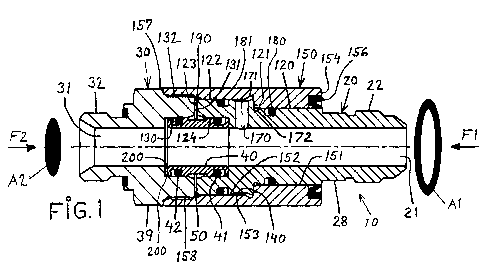
La présente invention concerne un joint articulé, en particulier, conçu pour raccorder deux conduits ou tuyaux tournant l'un par rapport à l'autre. Le joint articulé (10) comprend un premier élément central (20) pourvu d'un orifice et comprenant une portion d'attache (22) permettant la fixation d'un premier conduit, le joint articulé (10) comprend un second élément central (30) pourvu d'un orifice et comprenant une partie d'attache (32) permettant la fixation d'un second conduit, le premier élément central (20) et le second élément central (30) pivotant l'un par rapport à l'autre. Les éléments centraux (20, 30) sont maintenus ensemble au moyen d'un manchon externe (150) qui est ancré à une extrémité au second élément central (30) et à l'autre l'extrémité disposé de manière à coulisser par rotation par rapport au premier élément central (20). Un premier palier à coulissement axial (140) est ménagé entre le manchon externe (150) et le premier élément central (20) et un second palier à coulissement axial (190) est ménagé entre le premier élément central (20) et le second élément central (30). Le premier élément central (20) est mobile axialement entre une première position dans laquelle le premier palier à coulissement axial (140) est fonctionnel et une seconde position dans laquelle le second palier à coulissement axial (190) est fonctionnel.


Abrégé anglais

The invention relates to a swivel device, in particular designed to connect two pipes or hoses rotating relative to one another, wherein the device (10) includes a first centre part (20) provided with a hole and comprising a fastening portion (22) for the attachment of a first pipe, the device (10) includes a second centre part (30) provided with a hole and comprising a fastening portion (32) for the attachment of a second pipe, the first centre part (20) and the second centre part (30) being rotatable relative to one another. The centre parts (20, 30) are held together by means of an outer sleeve (150) anchored at one end to the second centre part (30) and at its other end arranged in a rotationally slidable manner relative to the first centre part (20). A first axial sliding bearing (140) is arranged between the outer sleeve (150) and the first centre part (20) and a second axial sliding bearing (190) is arranged between the first centre part (20) and the second centre part (30). The first centre part (20) is axially displaceable between a first position in which the first axial sliding bearing (140) is operative and a second position in which the second axial sliding bearing (190) is operative.

Revendications

Note : Les revendications sont présentées dans la langue officielle dans laquelle elles ont été soumises.


6
Claims
1. Swivel device, in particular designed to connect two pipes or hoses
rotating relative to one another, wherein the device (10) includes a first
centre part (20) provided with a hole and comprising a fastening portion
(22) for the attachment of a first pipe, the device (10) includes a second
centre part (30) provided with a hole and comprising a fastening portion
(32) for the attachment of a second pipe, the first centre part (20) and the
second centre part (30) being rotatable relative to one another,
characterised in that the centre parts (20, 30) are held together by
means of an outer sleeve (150) anchored at one end to the second centre
part (30) and at its other end arranged in a rotationally slidable manner
relative to the first centre part (20), that a first axial sliding bearing
(140) is
arranged between the outer sleeve (150) and the first centre part (20) and
that a second axial sliding bearing (190) is arranged between the first
centre part (20) and the second centre part (30).
2. Swivel device according to claim 1, characterised in that the first centre
part (20) is axially displaceable between a first position in which the first
axial sliding bearing (140) is operative and a second position in which the
second axial sliding bearing (190) is operative.
3. Swivel device according to claim 1 or claim 2, characterised in that a
tubular part (40) is arranged inside the swivel device (10) in order to cover
a gap (50) between the first centre part (20) and the second centre part
(30).
4. Swivel device according to claim 3, characterised in that the gap (50)
allows for limited axial movement between the first centre part (20) and
the second centre part (30).

7
5. Swivel device according to any one of claims 1-4, characterised in that
the first centre part (20) comprises a through connection (170) between its
centre hole (21) and its circumferential surface.
6. Swivel device according to any one of claims 1-5, characterised in that a
first pressure area (A1) is defined by the difference in diameter between
two steps (122, 120) on the first centre part (20), and that a second
pressure area (A2) is defined by the dimension of the diameter of a recess
(130) in the second centre part (30).
7. Swivel device according to claim 6, characterised in that the first
pressure area (A1) and the second pressure area (A2) are identical in
size.
8. Swivel device according to claim 6, characterised in that the first
pressure area (A1) is larger than the second pressure area (A2).
9. Swivel device according to claim 6, characterised in that the second
pressure area (A2) is larger than the first pressure area (A1).

Description

Note : Les descriptions sont présentées dans la langue officielle dans laquelle elles ont été soumises.


CA 02794548 2012-09-25
WO 2011/119085 PCT/SE2011/000055
Swivel device
Technical field
This invention relates to a swivel device according to the pre-characterising
part of claim 1.
Background of the invention
So-called swivels or swivel devices are used when a medium, e.g. hydraulic
oil, is to be transferred between two pipes/tubes/hoses rotating relative to
one
another.
Aim of the invention
The aim of this invention is to provide an extremely advantageous swivel
device. This aim is achieved in that the device has the features specified in
the claims.
Advantages of the invention
The advantages of the invention include the following.
The swivel device is rotated very easily as a result of the fact that axial
loading
of the device is reduced, eliminated or adapted to the current operating
conditions.
Integral bearings result in dimensioning advantages.
The invention offers both technical and economic advantages.
Brief description of the drawings
Embodiments of the invention will now be described with reference to the
accompanying drawing.
Figure 1 is a longitudinal section through a swivel device according to the
invention.
Figure 2 is a perspective view of the swivel device according to Fig. 1.

CA 02794548 2012-09-25
WO 2011/119085 PCT/SE2011/000055
2
Detailed description of illustrated embodiment
The swivel device 10 illustrated in Figures 1 and 2 includes a first centre
part
20 and a second centre part 30 and an outer sleeve/coupling part 150
operative between the said parts 20, 30.
The first centre part 20 includes a circular centre hole 21 and has a threaded
fastening portion 22 for the attachment of a first connecting hose via a
coupling device. The first centre part 20 furthermore comprises a circular
first
step 120 passing over via a shoulder 121 into a circular second step 122
connected to an end portion 123. The step 122 comprises a circular recess
124 at its end portion 123. The first centre part 20 also comprises a key grip
28 to facilitate assembly.
The second centre part 30 includes a circular centre hole 31 and has a
threaded fastening portion 32 for the attachment of a second hose via a
coupling device. The second centre part 30 furthermore comprises a circular
recess 130 in its end portion 131 directed away from the fastening portion 32.
The second centre part 30 furthermore comprises an external threaded
portion 132. The second centre part 30 furthermore has a key grip 39 to
facilitate assembly.
According to the invention, a circular sleeve or a circular tube 40 is
arranged
in the recesses 124 and 130, as will be clear from Fig. 1. The sleeve/tube 40
bridges a gap 50 present between the end portions 123 and 131. The sleeve
40 means that the gap 50 is covered, this being very advantageous from the
point of view of axial loading as the pressure medium cannot overcome
pull-apart pressure of the end portions (end planes) 123 and 131. Seals 41,
42 are arranged between the sleeve 40 and the recesses 124 and 130 in
order to prevent the pressure medium from reaching the gap 50. The seals
41, 42 are arranged in external grooves in the sleeve/tube 40. The sleeve 40

CA 02794548 2012-09-25
WO 2011/119085 PCT/SE2011/000055
3
cooperates like a sliding bearing with circumferential portions 124 and 130 of
the first and second centre parts.
The swivel device 10 furthermore includes a first axial sliding bearing 140
designed to support axial forces applied to the swivel device. The end
portions 123 and 131 at the gap 50 are also designed to support axial forces
in the event of certain loads and serve as a second axial sliding bearing 190.
A circular outer sleeve 150 with a nut function is designed to hold the
components of the swivel device 10 together, as will be clear from Fig. 1. The
outer sleeve 150 comprises two circular steps 151, 152 and a shoulder 153
arranged therebetween. The outer sleeve 150 is provided at its first end 154
with a recess for a seal 156. The outer sleeve 150 is provided at its other
end
157 with an internal thread 158 cooperating with the threaded portion 132 of
the second centre part 30 so as to allow for appropriate tightening. The outer
sleeve 150 comprises an external key grip 159.
A radial hole 170 is arranged in the first centre part 20. The hole extends
between the centre hole 21 and the circumference of the second step 122.
The hole 170 is designed in such a manner that pressure medium is available
to and lubricates the axial bearing 140. Seals 180 and 181 are arranged in
external grooves in each step of the first centre part 20, the seals 180, 181
operating between the first centre part 20 and the outer sleeve 150. The
seals 180, 181 are disposed in such a manner that the hole 170 and the axial
bearing 140 are situated between the seals, as will be clear from Fig. 1.
An annular recess 171 is arranged inside the outer sleeve 150 in order to
facilitate communication between the hole 170 and the axial bearing 140 for
the pressure medium. An annular groove 172 is arranged on the first step
120 on the first centre part 20 at the axial bearing 140.

CA 02794548 2012-09-25
WO 2011/119085 PCT/SE2011/000055
4
There is a sliding bearing function between the circumferential surfaces of
the
steps 120 and 122 and opposing step surfaces on the outer sleeve 150. The
sleeve 40 also participates in the rotational movement.
Pressure medium loading generates an axial force F1 tending to reduce the
size of the gap 50 and simultaneously increase the axial gap of the sliding
bearing 140. This takes place as a result of the difference in diameter
present
between the steps 122 and 120. The hole 170 and the seals 180, 181 and
relevant gaps ensure the intended pressure medium effect. A pressure area
Al resulting in the generation of the force F1 is defined by the difference in
area between the steps 122 and 120. The force F1 can as a maximum
displace the first centre part 20 relative to the second centre part 30 so
that
the end portions 123 and 131 bear against one another, thereby eliminating
the gap 50.
Pressure medium loading generates a further axial force F2 tending to
increase an axial gap 200 between the second centre part 30 and the sleeve
40. The current pressure area A2 is defined by the diameter of the recess
130. The pressure area A2 gives rise to the force F2 which can as a
maximum displace the first centre part 20 relative to the second centre part
30
so that the axial bearing 140 has no gap. The seals 42 ensure the intended
pressure medium effect.
By varying the pressure areas Al and A2, the axial forces F1 and F2 can be
selected in such a manner that the desired resultant force is obtained. A
desired mode of operation can therefore be selected for the swivel device 10
by varying the dimensions. External axial forces acting on the swivel device
in its operating environment may also be taken into account in this
connection.

CA 02794548 2012-09-25
WO 2011/119085 PCT/SE2011/000055
It is therefore possible to select different normal positions for the swivel
device
by dimensioning the pressure areas Al and A2 in such a manner that the
forces F1 and F2 are of identical magnitude or in such a manner that the said
forces are of different magnitude. In a preferred embodiment, F1 is selected
in such a manner that it is slightly larger than F2, inter alia, taking
external
loading into account.
It is thus also possible to select which of the axial sliding bearings 140 and
190 will be most active.
The swivel device 10 is rotated very easily in accordance with the design
concept of the invention.
All of the seals are arranged externally, this being simpler from the point of
view of manufacture and assembly. According to the invention, the seals
isolating the pressure areas are arranged in three different diametric planes.
It will be clear that the number of seals may of course be varied as required.
The components forming part of the swivel device 10 are of course lubricated
as required in connection with the assembly thereof.
It will furthermore be clear that the design of the components of the swivel
device 10, such as, e.g. the fastening portions, may of course be varied
considerably within the scope of this inventive concept.
The invention is not limited to what is illustrated and described here and
amendments and modifications are of course possible within the scope of the
accompanying claims.
------------

Dessin représentatif
Une figure unique qui représente un dessin illustrant l'invention.
États administratifs

2024-08-01 : Dans le cadre de la transition vers les Brevets de nouvelle génération (BNG), la base de données sur les brevets canadiens (BDBC) contient désormais un Historique d'événement plus détaillé, qui reproduit le Journal des événements de notre nouvelle solution interne.

Veuillez noter que les événements débutant par « Inactive : » se réfèrent à des événements qui ne sont plus utilisés dans notre nouvelle solution interne.

Pour une meilleure compréhension de l'état de la demande ou brevet qui figure sur cette page, la rubrique Mise en garde , et les descriptions de Brevet , Historique d'événement , Taxes périodiques et Historique des paiements devraient être consultées.

Historique d'événement

Description Date
Le délai pour l'annulation est expiré 2016-03-29
Demande non rétablie avant l'échéance 2016-03-29
Réputée abandonnée - omission de répondre à un avis sur les taxes pour le maintien en état 2015-03-25
Inactive : Page couverture publiée 2012-11-26
Inactive : Notice - Entrée phase nat. - Pas de RE 2012-11-20
Inactive : Demandeur supprimé 2012-11-20
Demande reçue - PCT 2012-11-20
Inactive : CIB en 1re position 2012-11-20
Inactive : CIB attribuée 2012-11-20
Exigences pour l'entrée dans la phase nationale - jugée conforme 2012-09-25
Demande publiée (accessible au public) 2011-09-29

Historique d'abandonnement

Date d'abandonnement Raison Date de rétablissement
2015-03-25

Taxes périodiques

Le dernier paiement a été reçu le 2014-02-26

Avis : Si le paiement en totalité n'a pas été reçu au plus tard à la date indiquée, une taxe supplémentaire peut être imposée, soit une des taxes suivantes :

  • taxe de rétablissement ;
  • taxe pour paiement en souffrance ; ou
  • taxe additionnelle pour le renversement d'une péremption réputée.

Les taxes sur les brevets sont ajustées au 1er janvier de chaque année. Les montants ci-dessus sont les montants actuels s'ils sont reçus au plus tard le 31 décembre de l'année en cours.
Veuillez vous référer à la page web des taxes sur les brevets de l'OPIC pour voir tous les montants actuels des taxes.

Historique des taxes

Type de taxes Anniversaire Échéance Date payée
TM (demande, 2e anniv.) - générale 02 2013-03-25 2012-09-25
Taxe nationale de base - générale 2012-09-25
TM (demande, 3e anniv.) - générale 03 2014-03-25 2014-02-26
Titulaires au dossier

Les titulaires actuels et antérieures au dossier sont affichés en ordre alphabétique.

Titulaires actuels au dossier
INDEXATOR GROUP AB
Titulaires antérieures au dossier
JOAKIM HARR
NICLAS KARLSSON
OLOF FRIDOLFSSON
Les propriétaires antérieurs qui ne figurent pas dans la liste des « Propriétaires au dossier » apparaîtront dans d'autres documents au dossier.
Documents

Pour visionner les fichiers sélectionnés, entrer le code reCAPTCHA :


Pour visualiser une image, cliquer sur un lien dans la colonne description du document. Pour télécharger l'image (les images), cliquer l'une ou plusieurs cases à cocher dans la première colonne et ensuite cliquer sur le bouton "Télécharger sélection en format PDF (archive Zip)" ou le bouton "Télécharger sélection (en un fichier PDF fusionné)".

Liste des documents de brevet publiés et non publiés sur la BDBC .

Si vous avez des difficultés à accéder au contenu, veuillez communiquer avec le Centre de services à la clientèle au 1-866-997-1936, ou envoyer un courriel au Centre de service à la clientèle de l'OPIC.


Description du
Document 
Date
(aaaa-mm-jj) 
Nombre de pages   Taille de l'image (Ko) 
Description 2012-09-24 5 189
Revendications 2012-09-24 2 62
Dessins 2012-09-24 1 30
Abrégé 2012-09-24 1 73
Dessin représentatif 2012-11-20 1 17
Avis d'entree dans la phase nationale 2012-11-19 1 193
Courtoisie - Lettre d'abandon (taxe de maintien en état) 2015-05-19 1 173
Rappel - requête d'examen 2015-11-25 1 125
PCT 2012-09-24 10 332