Note : Les descriptions sont présentées dans la langue officielle dans laquelle elles ont été soumises.
CA 02794856 2012-09-27
- 1 -
Regulation System in A Wind Turbine
The invention relates to a wind turbine having a wind
rotor, a generator driven by the latter and which
interacts with a converter to generate electrical
power, a speed regulator, and a converter control unit
interacting with the latter, the speed regulator
outputting a target speed signal to the converter
control unit.
As wind turbines become increasingly widespread, there
is a requirement for them to make significant
contributions to the stability of the grid. An
important aspect here is the provision of so-called
balancing power. This is traditionally usually provided
by conventional power stations, in particular coal- or
gas-fired power stations, and to be precise in the form
of power that can be additionally called up within a
few seconds (primary balancing power). In order to be
able to ensure such a rapid reaction, the corresponding
power stations must be kept running permanently. This
is expensive and entails a high consumption of fuel
that is in many cases not used at all when balancing
power is not called up. To reduce this cost, wind
turbines are also included in the supply of primary
balancing power.
A problem here is that for wind turbines the power
output is determined by the wind and cannot be
increased on demand, in contrast to conventional power
stations. In order to be able to use wind turbines to
provide primary balancing power, in spite of this
limitation, it is known to obtain the required primary
balancing power from the kinetic energy of the rotor.
Various methods have been developed to do this:
In a first method, the operating point of the wind
turbine is altered as a precautionary measure. The wind
CA 2794856 2018-05-23
CA 02794856 2012-09-27
- 2 -
turbine is adjusted, by changing certain operating
parameters and in particular the pitch angle of the
rotor blades, in such a way that it is operated
suboptimally (Janssens, N. et al: "Active Power Control
Strategies of DFIG Wind Turbines", IEEE Power Tech
2007, Lausanne, Switzerland, 1-5 July 2007). It is thus
possible to shift operating parameters on demand toward
the optimum operating point and thus to output more
power even with the same amount of wind and call it up
as primary balancing power. A disadvantage of this
approach is that, in normal operation (when there is no
demand for balancing power), less power is generated by
the wind turbine than is actually possible because of
the suboptimal operating point.
In an alternative approach, the operating point is
changed only when required, i.e. to draw off additional
electrical power as primary balancing power. The speed
regulator of the wind turbine is hereby modified in the
short term and the target value for the power to be
output is increased according to the primary balancing
power which needs to be additionally output (for
example by raising the target torque (Morren, J. et al:
"Wind Turbines Emulating Inertia and Supporting Primary
Frequency Control", IEEE Transactions on Power Systems,
vol. 21, no. 1, February 2006)). Although these and
other known methods are simple, they do not take
account of the influence of changes in the wind
conditions during the provision of primary balancing
power. These known methods are instead designed
exclusively for stationary operating conditions and
hence for unchanging wind conditions. This entails the
disadvantage that in the event of non-stationary wind
conditions - as are frequently encountered in practice
- only a relatively poor provision of primary balancing
power is achieved.
- 3 -
The object of the invention is to provide an improved
regulation system for wind turbines that provides
sufficient primary balancing power even in the event of
non-stationary wind speeds.
10 In a wind turbine having a wind rotor, a generator
driven by the latter and which interacts with a
converter to generate electrical power, a speed
regulator, and a converter control unit interacting
with the latter, the speed regulator outputting a
target speed signal, according to the invention an
additional regulation system is provided that has an
input for a desired additional power and is designed so
as to generate therefrom a change of speed signal,
taking into account a moment of inertia of the rotor,
and output it as an output signal that is added to the
target speed signal via a logical element.
The invention is based on the concept of, instead of
regulating the power output to the grid by the wind
turbine, controlling the energy derived from the
centrifugal mass of the wind rotor as it were at the
input to the system of the wind turbine). By
determining a signal for a change of speed from the
additional regulation system, the centrifugal mass of
the wind rotor is thus controlled and a certain amount
of energy derived. This energy corresponds to the
difference between the kinetic energy stored in the
centrifugal mass before and after the change of speed
has been taken into account. This enables the kinetic
energy called up from the wind rotor per unit of time
to be controlled as part of an "energy tracking"
process. The kinetic energy increases the mechanical
power acting on the generator, which can be converted
CA 2794856 2017-07-17
CA 02794856 2012-09-27
- 4 -
by the generator into a correspondingly increased
electrical power, as kinetic support power. The desired
primary balancing power is made available in this way.
The invention enables the additional power that is made
available to be drawn exclusively from the centrifugal
mass of the rotor, and the power generated by the wind
thus has no effect. The "metering" of the additionally
supplied power, i.e. the primary balancing power, is
thus effected solely via the change of speed signal. It
is independent of the actual amount of wind available
so that precise provision of the primary balancing
power is ensured even in the case of fluctuating wind
conditions, in particular even when the wind speed
falls markedly. The invention combines these
considerable advantages in terms of providing primary
balancing power with only low cost demands. There is in
particular no need for additional hardware and the
additional regulation system according to the invention
can generally be implemented in the operational control
system that is already present.
The term target speed signal is understood to be the
initial value of the speed regulation that is applied
as a parameter to the speed control system of the wind
turbine and/or to the generator or the converter
connected to the generator in order to set the
generator speed. In most cases this is a target speed
signal itself but it can also be a target torque
signal. These signals are also included under the term
"target speed signal" which is to be understood from a
functional point of view.
The converter control system is understood to be a
device that controls the output of electrical power via
the mechanical/electrical energy converter formed by
the generator and converter. It usually acts directly
CA 02794856 2012-09-27
- 5 -
on the converter but it is not excluded that it also
acts alternatively directly on the generator.
The additional regulation system is understood to be a
device that is independent from the speed regulation
system that is conventionally present as part of an
operating control system of the wind turbine. It
preferably has speed feedback.
A correction element is preferably provided that is
designed to modify parameters of the additional
regulation system as a function of the additional power
called up. These parameters also include the quantity
of the additional power. Using this correction element,
it can be taken into account that, when the additional
power is called up, the wind turbine runs as a result
at a reduced speed outside its optimum operating
conditions and consequently induces a loss of power. If
this induced loss of power is not taken into account,
this could result in the desired quantity of additional
power not being achieved. The correction element can
handle this in an appropriate fashion. The correction
element thus preferably has a characteristic element.
This establishes a correction value for the target
speed as a function of the additional power demanded.
An aerodynamic estimator is preferably also provided
that estimates the aerodynamic efficiency of the wind
rotor. The power that can be obtained from the wind and
- when additional power is called up - the loss of
power resulting from the deoptimization can be
determined from the determination of this efficiency,
together with the wind speed. To prevent this loss of
power from having an effect on the power output of the
wind turbine, the power specification can handle this
in an appropriate fashion. The initial value of the
aerodynamic estimator is thus added to the demand for
additional power by means of a logic element. The
CA 02794856 2012-09-27
- 6 -
stable provision of the additional power is thus
ensured in the event of high demands for additional
power for which significant changes to the aerodynamics
of the wind rotor can result. The wind speed is
preferably provided as an input value to the
aerodynamic estimator. It may be an actual measured
value. However, a wind observer is advantageously
provided that determines the wind speed from parameters
that are already present in the operating control
system, in particular the output electrical power, set
angle of the wind rotor and the rotor speed. It is thus
possible to achieve a particularly good operating
behavior of the aerodynamic estimator.
A suppression element is preferably also provided that
blocks the additional regulation system under full
load. This is based on the recognition that, when
operating under nominal load, i.e. at a wind speed
above the nominal wind speed, sufficient power can be
provided by the wind itself and there is therefore no
need to derive any required additional power from the
kinetic energy of the wind rotor. An unnecessary
reduction in rotor speed at high wind speed is thus
prevented. The suppression element advantageously has a
start module that is designed to permit a short-term
change in speed for changing additional power demands
and so to override the suppression module. Short-term
is here understood to be a period of approximately 2 to
60 seconds. This is based on the recognition that under
full load a few seconds are required to adjust the
pitch of the blades of the wind rotor in order to set a
new pitch angle with which the required additional
power can be derived from the wind. In order to bridge
this period until the new pitch angle is set, the
required additional power can be provided in the short
term from a speed reduction of the additional
regulator. The response behavior of the wind turbine to
= CA 02794856 2012-09-27
- 7 -
the requirement for additional power under nominal load
is thus improved.
In a preferred embodiment that may provide independent
protection, a module for monitoring threshold values is
provided that limits or deactivates the additional
regulation system as a function of the threshold value
being exceeded. As a result, when providing additional
power the wind turbine is not operated within an
operating range that damages or overloads the wind
turbine. In particular, threshold values of this type
are electrotechnical design limits such as apparent
current, active current or reactive current, voltages
or thermal limits on the semiconductors of the
converter, in particular a maximum permissible power.
The exceeding of the threshold value can, however, also
be the exceeding of a preferably speed-dependent
threshold torque (for example, implemented in a speed-
dependent characteristic element) so that operation
within an overloaded operating range is prevented by
limiting the additional regulator. In a particularly
preferred development, the module for monitoring the
threshold value monitors the exceeding of a threshold
value of the output value of the aerodynamic estimator.
It is thus indicated that a critical aerodynamic loss
has been exceeded so that, after providing the
additional power, the wind turbine requires a
disproportionate amount of power to resume the normal
speed. It is thus made possible to detect in advance,
as it were pre-emptively, negative effects from
providing the additional power on the ongoing operation
of the wind turbine, and possibly to limit the
provision of the additional power. It can thus in
particular be prevented that the recovery phase after
the additional power has been provided lasts for a
disproportionately long time and results in a
correspondingly reduced feeding of power to the grid.
CA 02794856 2012-09-27
- 8 -
The additional regulation system preferably also
comprises a torque limiting element. Thus when
additional power is required the torque that acts as a
whole is limited to a value that can be set. This value
that can be set can originate in stationary fashion or
preferably from a characteristic element. This not only
serves to prevent overloading of the drive train but
also, when using a characteristic element, has the
advantage that determined operating ranges can be
avoided or completed more quickly. It is thus in
particular expedient to design the torque limiting
element in such a way that the torque is greatly
limited in the synchronous speed range. The converter
is thus prevented from being overloaded.
In a preferred embodiment, the characteristic can be
switched from the originally used characteristic to a
characteristic with a higher torque. A characteristic
switching module is provided to do this that interacts
with the speed regulation system of the wind turbine.
When additional power is required, the characteristic
is switched to a different characteristic that provides
more torque than the original characteristic. The power
output can thus be increased immediately. The term
"characteristic" here includes both working and/or
threshold characteristics. Switching to a different
characteristic can be understood to be switching to a
different regulating characteristic and/or continuing
the regulation within a changed working range, in
particular one that is enlarged in terms of the
permissible torque.
In order to prevent overloading of in particular the
electrical components such as the generator and the
converter, this increase in power, which is in fact an
increase in active power, is combined with a limitation
of the reactive power output. The reactive power is
thus reduced so that the electrical components do not
CA 02794856 2012-09-27
- 9 -
exceed the maximum permissible currents. In many cases,
this can require the reactive power output not just to
be greatly limited but even to be blocked or "zeroed".
A device for determining the additional power is
preferably provided that is designed so as to determine
the additional power using the frequency measured in
the grid. As a result, there is no need to wait until a
central target value for the additional power has been
specified and instead it is possible to react
immediately after the disruption has occurred in the
electricity grid. Different alternative determining
regulators can thus be provided in the device for
determining the additional power. It may firstly be
provided that the additional power is determined in
proportion to the frequency deviation, the additional
power increasing as the size of the frequency deviation
grows. It may, however, secondly also be provided that
the additional power can be increased in a stepped
fashion depending on the specific values of the
frequency deviation. It may, however, thirdly also be
provided that the maximum possible additional power is
called up only after a certain frequency deviation has
been exceeded. The frequency deviation of the
determining regulator mentioned by way of example can
here be determined as a deviation of the actual value
of the frequency from a target value or target value
range of the frequency in the electricity grid.
The device for determining the additional power
preferably interacts with a dynamic module that
preferably determines the additional power from the
depth and/or the time gradients of a dip in the
frequency in the grid. In particular concrete
specifications from the grid operator as to how a wind
turbine should react to a dip in frequency by feeding
in additional power can thus be implemented
efficiently. This applies all the more so when
= CA 02794856 2012-09-27
- 10 -
different functions are implemented separately for the
beginning and end by means of an increasing element and
a decay element. It may thus be provided for example
that, when a frequency deviation is detected for a
certain period, for example 10 seconds, the wind
turbine additionally feeds in 10% additional power,
wherein thereafter the power output of the wind turbine
cannot drop below a certain percentage of the initial
value, i.e. must be for example at least 80% of the
power fed in before the frequency disruption for at
least 20 seconds. Other functions for increasing and
decay are of course possible.
The additional regulator preferably comprises a speed
gradient module that is designed to limit the remaining
power to minimum power after the supply of additional
power is completed. After the feeding-in of the
additional power is completed, the wind turbine
requires additional energy from the wind in order to
resume the speed range that is normal in the respective
wind conditions. After the generation of additional
power is completed, the speed gradient module causes
the speed to rise again as a priority (with a minimum
gradient) so that an aerodynamically favorable
operating range (ratio between speed and wind speed)
can be quickly restored. The speed is thus prevented
from dropping so far that the wind turbine generates so
little power that it switches itself off, no longer
meets its own power use, or falls below a minimum
torque that is necessary for secure operation of the
wind turbine. Only after a certain increase in speed
does a further build-up in speed occur with a maximum
gradient, so that power is now generated for feeding
into the grid (it preferably being necessary to observe
a minimum gradient that is now reduced). The invention
thus resolves the problem of conflicting objectives
that, after the feeding-in of the additional power is
completed, on the one hand as much power as possible
CA 02794856 2012-09-27
- 11 -
needs to continue to be fed in, and on the other hand
the wind turbine needs to be restored quickly to an
efficient and stable operating range.
The invention also relates to a wind farm having
multiple wind turbines that are each provided with a
wind rotor, a generator driven by the latter and with a
converter to generate electrical power, a speed
regulator of a converter control unit interacting with
it, the speed regulator outputting a target speed
signal, and a wind farm control center is also provided
for the high-level regulation of the wind turbines,
according to the invention an additional regulator
being provided on at least some of the wind turbines
that has an input for additional power and is designed
so as to generate a change of speed signal therefrom,
taking into account a moment of inertia of the rotor,
and to output it as an output signal that is added to
the target speed signal via a logic element, and the
wind farm control center having an inertia control
module that apportions required additional power to the
rotating wind turbines. This apportioning preferably
takes place in such a way that all the rotating wind
turbines are controlled without taking into account the
power output by them. It is thus achieved that as many
of the wind turbines as possible participate in
providing the additional power, and to be precise those
that currently output only a small amount of power. As
a result, not only is the load on such wind turbines
that output a high degree of effective power relieved,
but there is also a better stochastic distribution over
the wind farm so that wind-related fluctuations can be
compensated better stochastically.
The invention also comprises corresponding methods for
operating the wind turbine or the wind farm. Reference
is made to the explanation above for a more detailed
description.
CA 02794856 2012-09-27
- 12 -
The invention is explained in detail below with
reference to the attached drawings in which
advantageous exemplary embodiments are shown, in which:
Figure 1 shows an overview of a wind turbine in an
exemplary embodiment of the invention;
Figure 2 shows a circuit diagram of an additional
regulator and an additional correction element
according to the exemplary embodiment of the invention;
Figure 3 shows a diagram with operating parameters in
the case of a partial load;
Figure 4 shows a diagram with operating parameters in
the case of a full load;
Figure 5 shows a diagram of the mode of operation of
the additional correction element;
Figure 6 shows a diagram according to Figure 3 in the
case of non-stationary wind;
Figure 7 shows power diagrams for different wind farms;
and
Figure 8 shows diagrams for increase and decay
functions.
The main features of a wind turbine 1 according to an
exemplary embodiment of the invention have a
conventional design. It comprises a mast 10, on the
upper end of which a nacelle 11 is pivotably arranged
in an azimuth orientation. A wind rotor 12 that is
provided with multiple rotor blades 13 that can be
adjusted in terms of their set angle is rotatably
arranged on its end face. A pitch regulating device 23
CA 02794856 2012-09-27
- 13 -
is provided to adjust the set angle. The wind rotor 12
drives a generator 14 via a rotor shaft. The generator
generates electrical energy together with a converter
15 connected to it. The generator 14 is preferably
designed as a dual-feed asynchronous generator, to the
stator of which a line for conducting the electrical
energy is directly connected, the line also being
connected to the converter 15 that is joined in turn to
a rotor of the generator 14. The line 17 is connected
to a collection grid 9 within the wind farm via a
transformer that is not shown. It can also be connected
directly to a medium- or high-voltage grid 99 via a
transformer. Also arranged on the nacelle 11 is an
operating control unit 2 that is joined to a wind farm
control center 8 by communication means (not shown).
The operating control unit 2 manages the operation of
the wind turbine 1 and to do so is provided with
different specialized devices, including a speed
regulator 21 for the wind rotor 12. The electrical
power generated by the wind turbine 1 and output via
the line 17 is recorded by a power measurement device
18 and applied to the operating control unit 2.
The wind turbine I can stand on its own. However, it is
usually part of a wind farm that consists of multiple
wind turbines 1, 1'. The other wind turbines 1' have a
similar construction to the wind turbine 1 but it is
not excluded that different types of wind turbines are
also arranged in the wind farm. The wind farm control
center 8, which is joined to the individual wind
turbines 1, l' via communication means (not shown),
forms the high-level management center for the wind
turbines 1, 1'. The electrical power generated by the
different wind turbines 1, l' is directed, via a
collection grid 9 within the wind farm, to a link point
at which the wind farm is connected via a transformer
(not shown) to a medium- or high-voltage grid 99 that
has the purpose of transmitting energy.
= CA 02794856 2012-09-27
- 14 -
The operating control unit 2 comprises, with its speed
regulator 21, a unit that determines the target value
for a speed of the wind rotor 12 and interacts with a
converter regulator 25 in such a way that such an
electrical torque is set in order to obtain the
corresponding speed of the wind rotor 12. The speed
regulator 21 also interacts with the blade angle
regulator 23 in such a way that a specific angle of
attack of the rotor blades 13 (pitch angle) with
respect to the wind flowing onto them is set in order
to obtain a speed of the wind rotor 12. The interaction
of the speed regulator 21 with the converter regulator
25 and the blade angle regulator 23 is regulated with
the aid of the working point of the wind turbine 1. If
the wind conditions are such that the wind turbine 1
can be operated only below its nominal power
(alternatively also its nominal speed or the nominal
wind), one refers to operating under partial load and
the speed regulator interacts with the converter
regulator 25. If the wind conditions are such that the
wind turbine 1 can be operated with its nominal power,
one refers to operating under nominal load and the
speed regulator 21 interacts with the blade angle
regulator 23. Within the range of the transition from
operating under partial load to operating under nominal
load, it can be provided that the speed regulator 21
interacts simultaneously with both the blade angle
regulator 23 and the converter regulator 25.
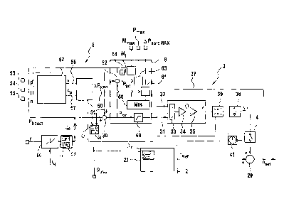
The corresponding output of the target value for the
speed from the speed regulator 21 is shown in Figure 2.
According to the invention, an additional regulator 3
is connected to this output line. To this effect, a
logic element 29 is provided in the line, is designed
as a summing element, and adds a value determined by
the additional regulator 3 to the target value for the
speed nref calculated by the speed regulator 21 in order
CA 02794856 2012-09-27
- 15 -
thus to generate the final target value net for the
converter control unit 25.
The additional regulator 3 has two inputs. A signal for
kinetic energy Pkin to be supplied is connected to its
first input 31. A signal for the target speed nset is
connected to its second input 32. The additional
regulator 3 has a division element 33 that divides the
value of the input 31 by that of the input 32.
Transformation using a constant factor by means of a P
element 34 results in a measure of the moment of
inertia O. This is divided by means of another P
element 35 by a constant factor that corresponds to the
rotational inertia J of the wind rotor 12. This results
in a value for a speed reduction that is supplied to an
integrator 36. The latter determines, by integration
over a cycle time, a discrete differential value for
the speed An that is connected to the logic element 29.
The corrected target value for the speed nset is thus
formed. The latter is fed back to the second input 32
of the speed regulator via a feedback line 37.
The mode of operation is that, when kinetic power is
required, a value for the moment of inertia 0 to be
supplied by the centrifugal mass of the wind rotor 12
is formed by division by the respective current target
value for the speed, and the necessary change of speed
is calculated therefrom, taking account of the
rotational inertia. This is added to the target value
for the speed output by the operating control unit 2
via the logic element 29.
In the case of high wind speeds, at which the wind
turbine 1 operates under nominal load, there is however
no need to feed additionally required power from the
kinetic energy of the wind rotor 12. A suppression
module 4 is provided to prevent an undesired reduction
in speed here. It is actuated by a nominal load signal
= CA 02794856 2012-09-27
- 16 -
that is made available by the operating control unit 2.
If it is present, then there is no reduction in the
values for the target speed output by the operating
control unit 2. However, a reduction in speed can
nevertheless advantageously be carried out dynamically,
i.e. at the beginning of the requirement to boost the
power or at its end. The purpose of this is to bridge
the period until the blade angle regulator 23 can
readjust sufficiently to provide the additional power
without any reduction in speed. To do this, a time
element 41 is preferably provided that enables the
target value for the speed to be corrected for the
period while the blade angle regulator 23 is active, as
described above.
An additional correction element 5 is optionally also
provided. It comprises an aerodynamic estimator 51 and
a wind observer 52. Inputs are provided at the wind
observer 52. The input 53 is for the electrical power
generated (measured by the sensor 18). The second input
is for the adjusted pitch angle that is transmitted by
the blade angle regulator 23. A value for the speed of
the generator 14 is supplied to a third input 55; this
is preferably a measured value that is established by a
sensor. The wind estimator 52 determines therefrom a
value for wind speed v that is output at an output 56.
A value for aerodynamic efficiency Op is also output at
an output 57. The aerodynamic estimator 51 is designed
so as to calculate the aerodynamically induced power
loss AP
- aero from the values for the wind speed v and
that for the aerodynamic efficiency cp. This can, for
example, take place by means of its two-dimensional
characteristic diagram. The corresponding value is
output by the aerodynamic estimator 51 at an output 50.
This value is added to an externally applied target
value for required additional power Pboost via a logic
element 30 and thus the value for the power Pkin to be
provided from the kinetic system, which is applied to
= CA 02794856 2012-09-27
- 17 -
the additional regulator 3, is established. The value
for the additional power required Pboost can optionally
also be generated locally at the wind turbine 1. To do
this, a device for determining the additional power 44
is provided, to the input of which a signal for the
frequency in the collection grid 98 is applied. If
there are deviations from a target frequency fnom that
can be set, then additional power is required. Its
magnitude can be preset or is preferably determined
from the degree of the frequency deviation. The device
for determining the additional power 44 is expediently
provided with a characteristic element for this
purpose.
A threshold value monitoring module is optionally
provided that is designated as a whole by the reference
number 6. It comprises as a core element a limiter 69
that limits the signal for the power Picõ, to be provided
from the kinetic system to a maximum value. This aspect
of the invention may provide independent protection.
The limiting can be to a fixed maximum value but is
preferably performed adaptively and for multiple
parameters. This is explained in detail below. The
threshold value monitoring module 6 comprises multiple
threshold signal modules 61, 63, 65 (three in the
example shown). They are designed so as to monitor
certain parameters with respect to predefinable
threshold values and to transmit a corresponding signal
to an evaluation logic circuit 60. Signals for the
aerodynamic power loss AP
- aero calculated by the
aerodynamic estimator 51 and a predefinable maximum
power loss value AP
- aeroMAX for example APaeroMAX ¨ 2 0 % of
nominal power, are applied to a first threshold signal
module 61. The threshold signal module 61 compares
these values and, when the maximum power loss value is
exceeded, outputs its value to the evaluation logic
circuit 60. Connected in series with a second threshold
signal module 63 is a summing element 62 to which
= CA 02794856 2012-09-27
- 18 -
signals for the power of the wind turbine from the
input 53 and for the required kinetic power P]õn are
applied and from which a total power demand Ptot is
formed and is applied to the second threshold signal
module 63 as an input signal. A signal for a maximum
permissible power Pmax is also applied to the second
threshold signal module 63. If this value is exceeded,
the second threshold signal module 63 outputs just this
value to the evaluation logic circuit 60. A third
threshold signal module 65 monitors whether the torque
Mb resulting from the power requirement remains below a
permissible limit. A division element 64, that divides
the total required power Ptot by the speed, for example
applied by the input 55, and so determines the required
torque Mb, can be provided to determine this torque. If
It exceeds a permissible threshold torque Mmax, a
correspondingly limited value is transmitted to the
evaluation logic circuit 60.
The evaluation logic circuit 60 evaluates the various
applied signals and determines therefrom a maximum
value that is applied to the limiter 69. In the
exemplary embodiment shown, the evaluation logic
circuit 60 is designed as a select low logic circuit in
which the lowest threshold value is decisive.
A characteristic switch module 24 for the speed
regulator is optionally provided. In addition to the
basic characteristic used in normal operation (see
dashed line), it has at least one other characteristic
that provides an increased torque (see solid line). It
may also alternatively be provided that the
characteristic switch module 24 provides a limiting
characteristic for the normal operation and at least
one limiting characteristic for a wider torque range
(see dotted line) so that a wider operating range is
made available to the torque/speed regulator.
CA 02794856 2012-09-27
- 19 -
A switch 42 with a fade-in/out element 43 is provided
to actuate the characteristic switch module 24. The
switch 42 monitors the signal transmission for the
required additional power Pboost and switches on when it
is required and actuates the characteristic switch
module 24. More active power is generated immediately
by increasing the torque. In order to prevent an
overcurrent, the output of reactive current is
simultaneously greatly reduced or blocked altogether.
To do this, a corresponding blocking signal ()block is
output to the operating control unit 2. After the
supply of required additional power is completed, a
transition to restore normal operation takes place.
However, this happens gradually rather than abruptly,
in order to prevent lack of stability in the mechanical
and electrical system of the wind turbine. To do this,
the characteristic switch module 24 does not switch
immediately back to normal operation but interacts with
the fade-in/out element 43 in such a way that the
original characteristic of normal operation is
gradually restored. The fade-in/out element 43 is here
designed in such a way that the original characteristic
is resumed only when the wind turbine has resumed its
normal operating point. To do this, the fade-in/out
element 43 evaluates the signal for the aerodynamic
power loss APaero = If this value is zero or below a
threshold that can be set, the normal operating point
is resumed. It may also be provided that this fading in
and out is performed by controlled switching to one or
more transition characteristics.
A speed gradient module 39 is also provided. At the
input 31, it monitors the discontinuation of the
additional power requirement. A signal for the speed n
of the wind rotor 14 is also applied. The speed
gradient module 39 comprises a maximum and minimum
gradient limiter. It is actuated at the end of the
additional power requirement. At this point, the speed
CA 02794856 2012-09-27
- 20 -
n of the wind rotor 14 is reduced from the initial
value because of the removal of kinetic energy. The
reduction may be considerable so that the wind rotor
operates far outside its optimum operating conditions.
A minimum gradient is therefore preset first so that
the speed rises again quickly. The rise in speed is
thus prioritized. On the other hand, too rapid a rise
is prevented by a maximum gradient so that there is
still sufficient power available to generate electrical
energy. When a switching speed is reached, the maximum
and minimum gradients are preferably modified, and to
be precise reduced. The generation of energy to load
the rise in speed is thus prioritized, the rise in
speed then usually taking place more slowly.
The behavior shown in Figure 3 thus results when
operating under partial load. The wind speed can be
assumed to be constant, as shown in Figure 3A.
Accordingly, the pitch angle of the rotor blades 13 is
also constant (see Figure 3B). At the point t=25
seconds, a requirement for 100 kW of boosted power is
applied for 10 seconds (see dashed line in Figure 3).
The additional regulator 3 continually determines a
change of speed that is added to the original target
value, resulting in a continual drop in speed in the
period t=25 to t=35 seconds. As a result of this drop
in speed, the kinetic energy in the wind rotor 12 is
reduced, the resulting power is supplied to the
generator and converter 14, 15 as additional power and
output via the line 17 as primary balancing power
(solid line in Figure 3). At the end of the
requirement, from the point t=35 seconds, the speed of
the wind rotor 12 has dropped considerably so that
subsequently the originally fed-in power cannot be set
immediately but only after the speed has risen
gradually (because of the relatively low wind speed it
lasts for a considerable length of time, until the
point t=80 seconds). The speed gradient module 39
CA 02794856 2012-09-27
- 21 -
hereby prioritizes the speed build-up during the first
twenty seconds, whereas from t=55 the generation of
power is prioritized with a rise in speed that then
proceeds more flatly (lower speed gradient).
In Figure 4, a requirement for additional power from
t-25 seconds for 10 seconds is shown; in contrast to
the image in Figure 3, however, the wind turbine is
operating under nominal load. The wind speed (see
Figure 4A) is accordingly higher and is above the
nominal wind speed of 11 m/s. This enables the
additional power to be generated from the wind itself,
and for this reason the pitch angle of the rotor blades
13 needs to be adjusted; this is shown in Figure 4B. It
can be seen that the adjustment of the pitch angle
lasts for a short period of time, and to be precise for
approximately 2 seconds in the exemplary embodiment
shown. In order to be able to continue to provide the
required additional power during this period too, the
speed is reduced by the suppression module 4 in
conjunction with its start module 41 at the beginning
of the requirement for additional power, as described
above. This can be stopped when the pitch angle has
reached its value at the point t=28 seconds. The
suppression module 4 then prevents the speed reduction
so that the speed then rises again and slowly reaches
its initial value. The same thing is repeated, in
reverse, at the point t=35 seconds when there is no
longer a requirement for additional power. It can be
seen in Figure 4D that a good match between the
required power (dashed line) and the output power
(solid line) is achieved by the action of the start
module 41 in each case at the beginning and end of the
demand for the additional power at t=25 and 35 seconds
and by the suppression module 4 in the period in
between.
CA 02794856 2012-09-27
- 22 -
The mode of operation of the aerodynamic estimator 51
is shown in detail in Figure 5. Operation is again
under partial load (compare Figure 3), in which
additional power is required at point t=25 seconds for
10 seconds. The additional power is provided by a
continual speed reduction (see Figure 5A), as a result
of which the electrical power can be increased by the
required value (see Figure 5B). Because the aerodynamic
conditions at the wind rotor 12 become poorer and
poorer as the speed falls, the wind turbine 1 operates
in a deoptimized fashion. The resulting induced loss of
power is determined by the aerodynamic estimator 51.
This value is shown in Figure 5C. It can be seen that
this value reaches a magnitude that is more than half
of the additional power made available and so cannot be
ignored. Despite this considerable induced loss, thanks
to the aerodynamic estimator 51 provided the required
additional power can be provided in a stable fashion
over the period.
Figure 6 shows the behavior of the additional regulator
3 according to the invention in the case of non-
stationary wind conditions, in particular when there is
increasing wind. As in the case shown in Figure 3 too,
additional power is required at point t=25 seconds for
10 seconds. At the same time, the wind speed (Figure
6A) begins to rise. The required power (which does not
take into account the rise in wind speed that was not
known in advance) is shown with a dashed line in Figure
6D. The actual power output is shown with a solid line.
It can be seen that the actual power output by the wind
turbine rises together with the rise in wind speed, and
yet excess power - as required - is output, as can be
seen clearly by the drop in the power output at the
point at which the requirement ends at t=35 seconds.
Thanks to the additional regulator according to the
invention, use can thus be made of both the increased
wind speed and the power supply that is increased
CA 02794856 2012-09-27
- 23 -
thereby, and moreover the required additional power can
additionally be provided to effect the primary
balancing. This shows that the invention works
optimally for non-stationary conditions too.
The application of the invention in a wind farm having
multiple wind turbines is shown in Figure 7. Figure 7A
functions as a reference and shows a single wind
turbine, Figure 7B shows a wind farm with 10 wind
turbines, Figure 7C shows a wind farm with 50 wind
turbines, and Figure 7D shows a wind farm with 240 wind
turbines. In each case, a requirement for additional
power amounting to 5% of the installed power occurs for
10 seconds at the point t=60 seconds. In the case of
the single wind turbine, it is barely possible to tell
that this additional power has been satisfied because
the corresponding rise in power is obscured by the
power differences caused by modified wind speeds. In
the case of a wind farm with ten wind turbines (Figure
7B), the stochastic changes in wind speed are partially
averaged out so that the additional power becomes more
visible. This effect is intensified for wind farms with
more wind turbines (Figure 7C and Figure 7D) and it can
ultimately be seen in Figure 7D that the stochastic
fluctuations are virtually balanced out by the large
number of wind turbines. Large wind farms in which the
invention is applied are thus extremely well suited to
providing additional power.
In the case of a wind farm having a wind farm control
center, it may be provided that the required additional
power is distributed to the individual wind turbines by
the wind farm control center. The target value for the
additional power of the wind farm is distributed to the
individual wind turbines in proportion to the amount of
power it contributes to the total power of the wind
farm. However, the moments of inertia of the rotors of
all the wind turbines present in the wind farm can
= CA 02794856 2012-09-27
- 24 -
preferably be determined by the wind farm control
center and the target values for the additional power
of the individual wind turbines can preferably be
determined depending on the proportion of the moment of
inertia of the rotors of the individual wind turbines
in relation to the sum of the moments of inertia of the
rotors in the wind farm.
Two examples for different increasing and decay
functions for the additional power that needs to be fed -
in by the wind turbine in the event of a frequency
disruption are shown in Figures 8a and b. These
functions are implemented in a dynamic module 45 (see
Figure 2). Because the increase and decay functions
differ, they are each implemented independently in an
increasing element 46 and a decay element 47
respectively. In the case of Figure 8a, the increasing
element is designed in such a way that, when a grid
disruption occurs at the 10 sec point, 10% additional
power is additionally fed in, to be precise for 10
seconds. Immediately thereafter, the decay element 47
takes over, which removes the additional power and
ensures that at least 80% of the power fed in before
the frequency disruption occurred is fed in during the
recovery phase too, to be precise for 20 seconds. To do
this, the dynamic module 45 can expediently interact
with the abovedescribed gradient module 36.
A different dynamic curve is shown in Figure 8b. The
increase and decay here differ very markedly. It is
provided that, as soon as the frequency deviation
occurs at the 10 sec point, the increasing element 46
immediately switches to maximum additional power, which
then falls in a hyperbola for as long as the frequency
disruption continues (until approximately the 20 sec
point). The hatched area below the curve is hereby a
measure of the kinetic energy removed from the wind
rotor. When the frequency returns slowly to its
CA 02794856 2012-09-27
- 25 -
original value at the end of the disruption, the decay
element 47 can ensure, with a slight undershoot, that
the original situation is obtained after 30 seconds. By
means of such an implementation in the dynamic module,
the wind turbine can behave relative to the grid like a
large synchronous generator of a conventional power
station. By virtue of this aspect of the invention, its
good grid-supporting property can be transferred to the
wind turbine.