Note : Les descriptions sont présentées dans la langue officielle dans laquelle elles ont été soumises.
CA 02794910 2012-11-07
1066-002
DRYING RACK
CROSS-REFERENCE TO RELATED APPLICATION
The present application claims benefit of U.S. Provisional Patent
Application No. 61/641,264, filed May 1, 2012, the contents of which are
hereby
incorporated by reference in its entirety for all purposes.
FIELD OF THE INVENTION
The present invention relates to methods and devices for drying
harvested crops, plants or otherwise.
BACKGROUND / DESCRIPTION OF PRIOR ART
Certain consumable vegetation, such as crops, plants or otherwise,
require drying prior to use. With smaller yields, such as with indoor or
outdoor
gardens, it may be desirous to dry such vegetation within a home or small
building.
In these instances, the vegetation is draped or hung about a room to allow
airflow
through the vegetation. However, with indoor drying it can be difficult to
dedicate
suitable drying space without negatively effecting air flow and hence drying
time.
Prior drying devices provide the ability to drape and hang vegetation, but the
majority
are configured to be used outside. Accordingly, such devices are typically
bulky,
difficult to store and do no efficiently utilize space.
Accordingly, there is a need for improved methods and devices for
drying harvested crops, plants or otherwise. Further, there is a need for such
methods
and devices to be utilized indoors, in small areas and which efficiently
utilizes small
places while maintaining optimal air flow and minimizing drying time.
SUMMARY OF THE INVENTION
The present invention relates to improved methods and devices for
drying harvested crops. The present invention provides a portable drying rack
that is
configured for disassembly and easy storage. Further, the drying rack is
configured
for linkage with to drying racks and in particular another portable drying
rack of the
present invention. The drying rack of the present invention provides the
ability to
1
CA 02794910 2012-11-07
=
1066-002
maximize airflow through the plants while minimizing drying times. More so,
the
features of the present invention provide the ability to increase drying
space,
particularly in small indoor drying spaces, by effectively utilizing space
from ceiling
to floor by modularly connecting sections of the drying rack and/or by linking
drying
racks together.
In greater detail, in one aspect, the present invention provides a drying
rack. The rack includes a plurality of extension rods configured for
releasable
connection to one another. One of the plurality of extension rods includes a
collar
mount. The rack further includes at least one collar including a connector for
attachment to one of the plurality of extension rods. The at least one collar
further
includes a plurality of support arm connectors configured for releasable
connection
and cantilevered support of one or more support arms. The rack further
includes a
plurality of support arms connected to the at least one collar through the
plurality of
support arm connectors, wherein upon connection to the at least one collar the
support
arms extend cantilevered from the collar. The rack further includes a
connector
attached to at least one of the plurality of extension rods. The connector is
configured
for connection to a corresponding member and being suitable in strength for
providing
hanging support of the drying rack.
In another aspect, the present invention provides a portable drying
rack. The rack includes a plurality of extension rods threadably attached to
one
another, each of the plurality of extension rods include a collar mount formed
about
and extending along a length of a respective extension rod. The rack further
includes
a plurality of collars each including a connector comprising an opening formed
through a center portion of the collar for releasable attachment to one of the
collar
mounts through a friction fit. The at least one collar further includes a
plurality of
support arm connectors radially disposed about the center portion of the
collar
configured for releasable connection and cantilevered support of one or more
support
arms. The plurality of support arm connectors comprising openings and grooves
formed through a surface of each of the plurality of collars. The rack further
includes
a plurality of support arms connected to the at least one collar through the
plurality of
support arm connectors, wherein upon connection to the at least one collar
each
support arm is seated in one of the openings and grooves and extends
cantilevered
2
CA 02794910 2012-11-07
1066-002
from the collar. The rack further includes a hanging connector attached to at
least one
of the plurality of extension rods and configured for connection to a
corresponding
member. The hanging connector being suitable in strength for providing support
of
the drying rack.
The above-described and other features and advantages of the present
invention will be appreciated and understood by those skilled in the art from
the
following detailed description, drawings, and appended claims.
BRIEF DESCRIPTION OF THE DRAWINGS
Other objects, features, advantages and details of the present invention
appear, by way of example only, in the following detailed description of
preferred
embodiments of the invention, the detailed description referring to the
drawings in
which:
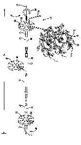
Fig. 1 illustrates a perspective view of an exemplary drying rack
according to the teachings of the present invention.
Fig. 2 illustrates a perspective view of an exemplary extension rod
according to the teachings of the present invention.
Figure 3 illustrates a perspective view of an exemplary collar
according to the teachings of the present invention.
Figure 4 illustrates a partial side elevational view of an exemplary
support arm according to the teachings of the present invention.
Figure 5 illustrates a cross-sectional view taken through the exemplary
drying rack shown in Figure 1.
Figure 6 illustrates a cross-sectional view taken through lines 6-6 of
the exemplary drying rack shown in Figure 5.
Figure 7 illustrates a perspective view of an exemplary storage and
carrying bag according to the teachings of the present invention.
DESCRIPTION OF THE PREFERRED EMBODIMENTS
Referring to Figs. 1 through 3, an exemplary embodiment of a portable
drying rack 10 of the present invention is shown. The drying rack 10 includes
a
3
CA 02794910 2012-11-07
.= =
1066-002
plurality of extension rods 12 releasably connected to one another. The
connected
extension rods 12 extend along an axis 'A' and between an first end 14 and
second end
16 of the drying rack 10 to establish and overall height 'H' of the drying
rack 10. The
extension rods 12 include a plurality of collar mounts 18 for releasable
attachment to
a plurality of collars 20. The collars 20 includes support arm connectors 22
for
releasable attachment of a plurality of support arms 24. The support arms
extend
radially outward from the axis 'A' and are suitable in strength for supporting
harvested
plants 25, such as herbs or otherwise. The drying rack 10 further includes a
hanging
connector 26 for hanging the drying rack from a corresponding member, such as
another hook, nail, tubing, another drying rack 10 or otherwise. Through the
configurations of the present invention, the drying rack is suitable in
strength for
supporting, storing and expediting drying of harvested plants 25, particularly
in
limited areas, such as small rooms or otherwise.
In greater detail, referring to Figures 1 and 2, the drying rack 10
includes one or more, preferably a plurality, of extension rods 12 that are
releasably
connected to one another. In the configuration shown, the drying rack 10
includes
three extension rods 12, an upper extension rod 28, lower extension rod 30 and
intermediate extension rod 32. However, through the configuration of the
drying
rack, a user can add or subtract more or less extension rods 12. For example,
in one
exemplary embodiment it is contemplated the drying rack 10 omits an
intermediate
extension rod 12 and merely utilizes the upper and lower extension rods 28,
30. In
another exemplary embodiment, it is contemplated that the drying rack 10
includes a
plurality of intermediate extension rods 32, such as 2, 3, 4 or more. As
should be
appreciated, the size and capacity of the drying rack can be changed to meet
needs
and size limitation. Further, the addition or subtraction of extension rods 12
would
alter the overall height 'H' of the drying rack 10.
The extension rods 12 are connected to one another through a
releasable attachment 34. In the configuration shown, referring to Figure 2,
the
releasable attachment 34 comprises a threaded engagement formed between
corresponding components of two extension rods 12. In this configuration, a
first end
36 of a first extension rod has a female portion of a threaded engagement and
a
second end 38 of another extension rod 12 has a male portion of the threaded
4
CA 02794910 2012-11-07
1066-002
engagement. The extension rods 12 further include hex clamping portions 40 for
facilitating in attachment and detachment of a first extension rod 12 to a
second
extension rod 12. Other releasable attachments may be utilized, such as snaps,
friction fits, hook and latch or otherwise, so long as the attachment is
suitable in
strength for supporting drying rack components and hanging plants therebelow.
In
one exemplary embodiment, the releasable attachment utilized to connect the
extension rods 12 are the same so as to selectively add or subtract the total
number of
extension rods used.
Referring to Figures 2, 5 and 6, as previously mentioned, the extension
rods 12 include collar mounts 18 for releasable connection to collars 20, as
described
herein. With reference to Figures 1 and 2, as shown, each extension rod 12
includes a
collar mount 18, which may be utilized to mount a collar 20, as desired by a
user of
the drying 10. However, it is contemplated that more or less collar mounts 18
may be
utilized on a single extension rod. For example, it is contemplated that some
extension rods 12 may have no collar mounts 18 and some extension rods may
have
multiple collar mounts, such as 2, 3, 4 or more. Advantageously, this allows a
user to
space out the collars 20 and hence support arms to help control the flow of
air through
the plants draped thereover. In one exemplary embodiment, it is contemplated
that
the collar mounts 18, and hence collars 20, are spaced approximate 12 inches
apart.
However, other spacing's are contemplated as well such as 6, 8, 10, 12, 14,
16, 18
inches or otherwise.
A mentioned, the collar mount 18 is configured to engage the collar 20.
In one configuration, the collar mount18 is cylindrically shaped and extends
along a
length of the extension rod 12 in which it is attached or formed therewith. In
this
configuration, the collar mount 18 is formed of a friction material, such as
rubber or
otherwise, to limit axial and rotational movement of the collar mount 18 with
respect
to a collar 20. This limited movement assist in preventing spinning and
possible
misbalancing of the drying rack 10. It is contemplated that other
configurations may
be used to connect the extension rods 12 to the collar 20, in particular
configurations
that limit rotational movement of the collar 20 with respect to an extension
rod 12.
Referring to Figures 3, 5 and 6, as previously mentioned, the drying
rack 10 further includes one or more, and in one preferred embodiment a
plurality, of
5
CA 02794910 2012-11-07
1066-002
collars 20. The collars 20 are mounted to the extension rods 12, via the
collar mounts
18, through extension rod connectors 42. In one exemplary embodiment, the
extension rod connectors 42 includes an extension rod opening 44 formed in a
center
portion of the collar and extending therethrough. The collar 20 further
includes a
channel 46 providing and side entrance to the extension rod opening 44. The
extension rod opening 44 has a first diameter 'D1' that is sized to receive a
collar
mount 18. In one exemplary embodiment, the first diameter 'D1' is similar to
an
exterior diameter 'D ext' of the collar mount 18 to form a friction fit
therebetween.
The opening 44 further includes a second diameter 'D2' that is smaller than
the
exterior diameter 'D ext' of the collar mount 18. The second diameter 'D2'
limits
movement of the collar 20 along the axis 'A' and more particularly towards the
second
end 16 of the drying rack.
The collar 20 includes a plurality of support arm connectors 22 for
attachment of support arms 24, as described herein. In one exemplary
embodiment,
the collar 20 includes an upper surface 50, facing in the direction of the
first end 14 of
the drying rack 10, in which the plurality of support arm connectors 22 are
formed. In
one exemplary embodiment, the support arm connectors 22 includes a plurality
of
radially disposed openings 52 extending through the collars 20 in a direction
generally
parallel to axis 'A'. The openings 52 are configured to receive end portions
of the
support arms 24. The support arm connectors 22 further includes a plurality of
grooves 54, formed through the upper surface 50, extending away from the axis
'A' in
a direction generally perpendicular to the axis 'A'. The openings 52 and
grooves 54
are aligned to be continuous. The grooves 54 are configured to receive
portions of the
support arm 24 to limit radial movement of the supports arms about the
openings 52.
In one exemplary embodiment, the collar 20 includes a plurality of
equally spaced support arm connectors 22, e.g. openings 52 and grooves 54,
formed
radially about extension rod opening 44. In one exemplary embodiment, the
collar
includes 8 support arm connectors 22, however, other configurations are
contemplated
such as 4, 5, 6, 7, 8, 9, 10 or more.
As previously mentioned, referring to Figures 1, 4, 5 and 6, the drying
rack 10, includes a plurality of support arms 24 for supporting harvested
plants. It is
contemplated that each collar 20 and support arm connectors 22 includes a
support
6
CA 02794910 2012-11-07
1066-002
arm 24. However, in certain embodiments, depending on the desires of the user,
some
collars 20 and/or support arm connectors 22 may not be used. In one exemplary
embodiment, the support arms 24 are releasably connected to the collars 20.
The support arms 24 includes a first end 56 configured for engagement
with the support arm connectors 22 and a second end 58 configured for
preventing
hanging plants from slipping off of the drying rack 10. The first end 56 of
the support
arm 24 includes a first finger 60 extending generally perpendicular to a main
body 62
of the support arm. The first finger 60 is shaped, sized and orientated to fit
within one
of the radially disposed openings 52. The second end 58 of the support arm 24
includes a second finger 64 extending generally in an opposite direction to
that of the
first finger 60. The second finger 64 includes a bulb 66 for further assisting
in the
prevention of plant slippage.
The support arms 24 are releasably connected to the collars 20 by
inserting the first finger 60 into the openings 52 until the support arm is
completely
seated. In one exemplary embodiment, the main body 62 of the support arm 24 is
seated within groove 54, which as previously mentioned limits or substantially
prevents rotational movement of the support arm 24 with respect to the opening
52
and collar 20.
Referring again to Figure 1, as previously mentioned, the drying rack
10 further includes a hanging connector 26 for hanging the drying rack from a
member, such as a corresponding components, e.g. nail, hook, another drying
rack or
otherwise. The hanging connector 26 is suitable in strength and shape for
hanging of
the drying rack from a ceiling member, another drying rack 10 or otherwise. In
one
exemplary embodiment, the first end 14 of the drying rack 10 includes the
hanging
connector 26. In one exemplary embodiment, the hanging connector comprises a
hook that is rotatably mounted to the an upper extension rod 12. Other
exemplary
hanging connectors 26 comprises loops, hook and latch configurations,
mechanical
fastening devices such as clamps or otherwise, or otherwise.
In one exemplary embodiment, the drying rack 10 further includes an
additional connector disposed at the second end 16 of the drying rack for
connecting
additional components, such as other drying racks or otherwise. Accordingly,
the
additional connector would be suitable in size and strength for supporting
such
7
CA 02794910 2012-11-07
1066-002
components. The additional connector disposed at the second end 16 of the
drying
rack 10 may comprise any of the connectors of the hanging connectors 26 or
otherwise. In another exemplary embodiment, the drying rack 10 may includes a
cap
68 disposed at the second end 16 of the drying rack.
In one exemplary embodiment, referring to Figure 7, the drying rack
further includes a portable carrying case, such as a bag 70, for storage and
transportation of the components of the drying rack. For example, in one
configuration it is contemplated that the support arms 24 are removed from the
collars
20, the collars are removed from the extension rods 12 and the extension rods
are
10 separated from one another. The components of the drying rack are then
placed in the
bag 70 and closed through a zipper or other closing means.
The components of the drying rack may be formed of any material
suitable in strength and resiliency to provide support harvested plants and
provide
resistance to surrounding environmental conditions. Examples of suitable
materials
include plastics, metals, rubbers, composites or otherwise. In one exemplary
embodiment, the extension rods 12 are formed plastic material, the collar
mount 18 is
formed of rubber and the hanging connector 26 is formed of metal and includes
a
plastic or rubber coating. Additionally, in one exemplary embodiment the
collar 20 is
formed of plastic and the support arms are formed of metal and include a
plastic or
rubber coating. Other suitable configurations are possible.
In one exemplary method of use, the components of the drying rack 10
are removed from bag 70 for assembly. The extension rods 12 are threadably
attached to one another until the drying rack 10 reaches a desired height 'H'.
The
desired number of collars 20 are then attached to the collar mounts 18 by
inserting the
extension rods 12 into the channels 46 and the collar mounts 18 are inserted
into
openings 44 until a top portion of the collar mounts abut the collars. A
desired
number and configuration of support arms 24 are then attached to the collars
20 by
inserting the first end 56 and more particularly the first finger 60 of the
support arms
into the openings 52 of the collars until the main body 62 of the support arms
are
seated into grooves 54. The drying rack 10 is then hung, via hanging connector
26,
and harvested plants are draped over the support arms of the drying rack. It
should be
appreciated that disassembly could be achieved in an opposite manner than
assembly.
8
CA 02794910 2012-11-07
1066-002
While the invention has been described with reference to a preferred
embodiment it will be understood by those skilled in the art that various
changes may
be made and equivalents may be substituted for elements thereof without
departing
from the scope of the invention. In addition, many modifications may be made
to
adapt a particular situation or material to the teachings of the invention
without
departing from the essential scope thereof. Therefore, it is intended that the
invention
not be limited to the particular embodiment disclosed as the best mode
contemplated
for carrying out this invention, but that the invention will include all
embodiments
falling within the scope of the appended claims.
9